Chapter 18 Simulation Testing of Knee Implants
Introduction to Wear Simulation
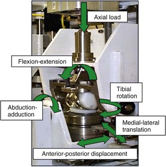
Numerous factors affect the in vivo performance of a TKR, including bearing design, material, lubrication, component position, patient loading and activity, and joint kinematics. Therefore, the performance of knee replacement bearings should be assessed in a physiologic simulator designed to replicate the in vivo conditions as closely as possible so the that interactions among all these variables may also be assessed.3 This is challenging, given the range of conditions to which knee replacements are subjected in vivo. Current studies have predominantly focused on simulating standard gait, whereas a wider envelope of conditions has been investigated more recently. Several different knee wear simulators have been developed both academically4,22,29 and commercially,17 and there are significant differences in the function and control of the simulators. Most current simulators use six degrees of freedom, four of which are actively controlled—axial load, anterior-posterior motion, internal-external rotation and flexion-extension (Fig. 18-1). The remaining two degrees of freedom, abduction-adduction and medial-lateral displacement, tend to be either free to move passively or, in some simulators, are fixed. Two hypotheses for the control of motion in the anterior-posterior direction have been proposed, and both are defined in standards: force control (ISO 14243-1)13 and displacement control (ISO 14243-3).14
The stability of a knee replacement in vivo is determined by a combination of the geometry of the implant and the natural soft tissues surrounding the joint. The relative contribution varies in different patients. Force-controlled simulator studies often use spring elements to represent the constraints to motion created by the soft tissues in vivo.6 The rationale for using force control has suggested that it generates the most representative kinematics and provides a better indication of the mechanical behavior of a specific design. A simple linear spring is not able to represent the complex force displacement relationships found in soft tissues. Additionally, the geometry of the implant also dictates its resistance to motion, and therefore the tensioning of the springs may not highlight the effect of geometric differences between bearings when testing under force control. Under displacement control, the actual movements are directly controlled and provide a more repeatable set of motion conditions and wear; the machine force is limited, which prevents the knee replacement experiencing excessive kinematics and ensures that the implant is not driven outside the geometric constraints.3
It is believed that the bearing type may dictate the appropriate test conditions. Because of differences in test conditions, implants studied, and simulator setup, it has been difficult to compare the two modes directly. However, studies of where identical implants have been tested in the same simulator, under load or displacement control, have been reported and have shown that similar levels of anterior-posterior translation have occurred under force and load control. A low-conforming, fixed-bearing study, in which rotation and anterior-posterior were controlled by force or displacement, also showed similar magnitudes of internal-external rotation, but the phase of the motion within the gait cycle differed significantly. The volumetric wear under load control was significantly higher than under displacement control. Low-conformity bearings and cruciate-retaining implants may undergo excessive displacement under load control testing.27 Conversely, high-conformity bearings, tested under displacement control, may be driven to excessive displacement, which would not occur physiologically, and therefore experience very high stress. Moderately conforming bearing, under both load and displacement control have been shown to generate equivalent wear volumes.16 There are obvious merits to both test hypotheses, depending on the design philosophy of the implant. Wear simulation studies should be conducted to produce clinically relevant kinematic profiles and wear data, and there is merit in simulation systems that have the flexibility to adopt both approaches to control on the anterior-posterior and rotation motion axes.3
Effect of Input Kinematics on Bearing Wear
Early wear simulator studies of total knee replacement produced very low wear rates, which was related to the input kinematics used for the simulations. It has been shown that the magnitude of anterior-posterior displacement and internal-external rotation has a significant effect on the wear of the polyethylene bearing. A standard displacement-controlled simulator study might use an anterior-posterior displacement of 0 to 10 mm and an internal-external rotation of ±5 degrees to re-create the motion within the natural knee (high kinematics). A 50% reduction in anterior-posterior displacement, while maintaining a ±5-degree rotation, has been shown to result in a twofold reduction in mean wear rate15 in fixed-bearing knees. Reducing the internal-external rotation to ±2.5 degrees while maintaining the 0- to 5-mm displacement resulted in a fourfold reduction in wear compared with high-kinematics studies. Removal of the internal-external rotation or the anterior-posterior displacement decreased the wear rate by an order of magnitude.17 A shorter anterior-posterior displacement results in a reduced sliding distance and therefore a reduced surface area of polyethylene to be worn. However, the significant change in wear resulting from reduced rotation in addition to displacement is caused by a change in the cross shear on the surface of the bearing. A reduction in rotation reduces the cross shear, therefore reducing the exposure of the polyethylene to wear in the strain softened direction. An increase in internal-external rotation results in an increased frictional force transverse to the sliding distance and therefore increases the wear in a fixed-bearing knee.
Liftoff of the femoral condyles from the tibial bearing has been shown in vivo through fluoroscopic studies. One experimental study has investigated the effect of liftoff on the wear performance of fixed and mobile total knee replacements, examining inserts with similar contact geometry.15 Condylar liftoff was achieved in the study by application of a rotation moment to the abduction-adduction axis to create 1 mm of lateral condyle liftoff during each gait cycle. A significant increase in wear rate was measured for fixed and mobile bearings, and it was notable that the reduced wear rates observed in the mobile knees compared with the fixed knees under standard gait conditions were not seen under liftoff. There was no significant difference between the wear rates of the bearings under liftoff conditions. The uneven loading of the insert during liftoff caused a medial-lateral shift, increasing the cross shear on the medial condyle and increasing the wear. This study showed liftoff to have a significant impact on the wear rate of the bearing; however, this test had liftoff during every cycle and the clinical translation of this research would depend on the frequency of liftoff in vivo.
Influence of Bearing Design on In Vitro Wear Performance of Knee Replacements
Comparison of Mobile and Fixed Bearings
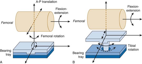
Fixed-bearing knees have an UHMWPE insert that clips or pushes into the tibial tray. Because the insert is fixed, it cannot move relative to the tibial tray and therefore all motion occurs on the superior surface of the insert at the articulation with the femoral bearing (Fig. 18-2A). Two types of mobile bearings exist: (1) those that allow anterior-posterior translation and internal-external rotation of the UHMWPE insert with respect to the tibial tray; and (2) rotating platform bearings, which permit rotation only at the insert–tibial tray interface. The rotating platform mobile bearing translates a complex input motion into simple uniaxial motions by decoupling the motion; linear motion parallel to the flexion-extension axis occurs on the superior surface and unidirectional rotational motion occurs on the inferior surface of the UHMWPE insert28 (see Fig. 18-2B).
Stay updated, free articles. Join our Telegram channel

Full access? Get Clinical Tree


