I. Consequences of Lower Extremity Deformity
A. Although degenerative arthritis has multiple etiologies, limb deformity may be one etiology due to:
1. Eccentric stress on joint
2. Shear stress on joint
B. Limb length inequality may cause:
1. Increased energy consumption with gait
2. Possible detrimental effect on hip and spine (controversial)
II. Skeletal Deformity Is a Vector
A. Like all vectors, a deformity has three components:
1. Magnitude—The magnitude of a skeletal deformity has six components.
• Three angulations—In a xyz three-dimensional coordinate system:
(a) Angulation in the xy (anteroposterior [AP]) plane is:
• Varus
• Valgus
(b) Angulation in the yz (lateral) plane is:
• Apex anterior
• Apex posterior
(c) Angulation in the xz plane is:
• Internal rotation
• External rotation
• Three translations—By convention in orthopedics, the direction of translation of the distal segment of the extremity with respect to the proximal segment determines the direction.
(a) Translation on the x-axis (AP plane)
• Medial translation
• Lateral translation
(b) Translation on the y-axis
• Lengthening
• Shortening
(c) Translation on the z-axis (lateral plane)
• Anterior translation
• Posterior translation
• A deformity may consist of a component in one, two, or three planes.
(a) A deformity with a component in more than one plane is not a biplanar or triplanar deformity; it is an oblique plane deformity.
(b) The magnitude of the oblique plane deformity is greater than the component of greatest magnitude in any of the three orthogonal planes.
2. Direction (or orientation)
3. Location
B. Standardized radiographic techniques are necessary to measure the magnitude, direction, and location of the deformity.
C. These three components can be used to accurately describe a deformity due to:
1. Malunion
2. Acute fracture
3. Developmental and congenital disorders
III. For accurate deformity correction, it is both necessary and sufficient to correct:
A. AP Mechanical Axis of the Extremity
B. Joint Orientation Angles in all Three Orthogonal Planes
C. Limb length inequality
IV. Mechanical Axis of the Lower Extremity
A. The mechanical axis of the lower extremity is a straight line from the center of the hip to the center of the ankle on the AP radiograph (Fig. 3-1).
B. In a normal lower extremity, the mechanical axis line intersects the knee at the center of the tibial spines or a maximum of 10 mm medial to the center of the spines.
C. The distance in millimeters from the center of the tibial spines to the mechanical axis is mechanical axis deviation (MAD) (Fig. 3-2).
1. Medial MAD is varus.
2. Lateral MAD is valgus.
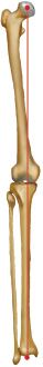
FIGURE 3-1 Mechanical axis of the lower extremity, which normally lies 0 to 10 mm medial to the knee joint center. (Adapted with permission from Brinker MR, O’Connor DP. Principles of malunions. In: Bucholz, RW, Court-Brown CM, Heckman JD, et al., eds. Rockwood and Green’s Fractures in Adults. 7th ed. Philadelphia, PA: Lippincott Williams & Wilkins; 2010.)
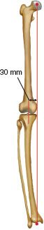
FIGURE 3-2 Medial mechanical axis deviation. (Reprinted with permission from Brinker MR, O’Connor DP. Principles of malunions. In: Bucholz, RW, Court-Brown CM, Heckman JD, et al., eds. Rockwood and Green’s Fractures in Adults. 7th ed. Philadelphia, PA: Lippincott Williams & Wilkins, 2010.)
D. Standardized radiographic imaging technique to insure accuracy and reproducibility requires:
1. A 51- × 14-in cassette with a variable grid to visualize the hip, knee, and ankle joints
2. A distance of 10 ft from the beam source to the film to minimize magnification and distortion, with the beam centered at the knee
3. Patient weight bearing, with weight equally distributed on both feet (Fig. 3-3)
• Patellas straightforward.
• Knees fully extended.
• If there is a limb length discrepancy, a block should be placed under the shorter extremity to level the pelvis and to keep the knees extended with weight evenly distributed.
4. Magnification can be calculated precisely by affixing a 30-mm ball bearing at the level of the bone and measuring the image of the ball bearing with calipers. Placing the ball bearing or a ruler with radiopaque graduations on the cassette will not facilitate measurement of magnification because they are closer to the film than the bone.
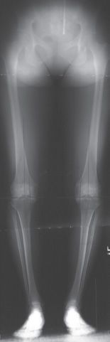
FIGURE 3-3 Bilateral weight-bearing 51-in AP alignment radiograph. (Reprinted with permission from Brinker MR, O’Connor DP. Principles of malunions. In: Bucholz, RW, Court-Brown CM, Heckman JD, et al., eds. Rockwood and Green’s Fractures in Adults. 7th ed. Philadelphia, PA: Lippincott Williams & Wilkins, 2010.)
E. There is no similarly defined mechanical axis of the lower extremity in the sagittal plane (lateral view) because the knee flexes and extends during the gait cycle. However, the following technique is used to obtain an image orthogonal to the AP view (Fig. 3-4).
1. The patella is directed lateral, 90° to the position on the AP view.
2. Only one extremity can be imaged on a 51- × 14-in film.
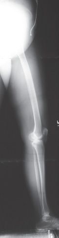
FIGURE 3-4 51-in lateral alignment radiograph. (Reprinted with permission from Brinker MR, O’Connor DP. Principles of malunions. In: Bucholz, RW, Court-Brown CM, Heckman JD, et al., eds. Rockwood and Green’s Fractures in Adults. 7th ed. Philadelphia, PA: Lippincott Williams & Wilkins, 2010.)
3. The pelvis is rotated slightly to avoid superimposing both lower extremities.
4. The imaged knee is in maximum extension.
V. Axes of the Femur and Tibia
A. AP Mechanical Axes of the Femur and Tibia—In addition to the mechanical axis of the lower extremity, there are mechanical axes of the femur and the tibia. In the normal lower extremity, the mechanical axis of the femur and the mechanical axis of the tibia coincide with the mechanical axis of the lower extremity. Just as normal mechanical axis of the lower extremity (colinearity of the hip, knee, and ankle) is necessary but not sufficient for accurate deformity correction, superimposable mechanical axes of the femur and tibia with the mechanical axis of the lower extremity are necessary but not sufficient for accurate deformity correction.
1. The AP mechanical axis of the femur is a straight line from the center of the hip to the center of the knee (Fig. 3-5).
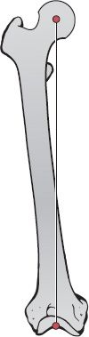
FIGURE 3-5 The mechanical axis of a long bone is defined as the line that passes through the joint centers of the proximal and distal joints. The mechanical axis of the femur is shown here. (Reprinted with permission from Brinker MR, O’Connor DP. Principles of malunions. In: Bucholz, RW, Court-Brown CM, Heckman JD, et al., eds. Rockwood and Green’s Fractures in Adults. 7th ed. Philadelphia, PA: Lippincott Williams & Wilkins, 2010.)
2. The AP mechanical axis of the tibia is a straight line from the center of the knee to the center of the ankle (Fig. 3-6).
B. Anatomic Axes of the Femur and Tibia—The anatomic axis of any long bone is a line formed by a series of mid-diaphyseal points. It is the site of a straight intramedullary nail.
1. AP femoral anatomic axis—The AP femoral anatomic axis is a straight line from the piriformis fossa, extending distally in the diaphysis to a point approximately 10 mm medial to the center of the knee in an average adult (approximately, the intersection of the concave intercondylar notch with the convex medial femoral condyle) (Fig. 3-7).
2. AP tibial anatomic axis—The AP tibial anatomic axis is a straight line formed by a series of mid-diaphyseal points. It is parallel to the lateral tibial cortex, approximately, 2 to 5 mm medial to the mechanical axis. Because the AP tibial mechanical and AP tibial anatomic axes are so close, they can be considered identical (Fig. 3-8).
3. Lateral femoral anatomic axis—Because of the normal bow of the femur in the lateral plane, a series of mid-diaphyseal points will not define a straight line. For deformity analysis, a best-fit straight line can be drawn for the proximal or distal segment of the femur. The intersection of the proximal and distal segments forms a 10° angle, apex anterior.
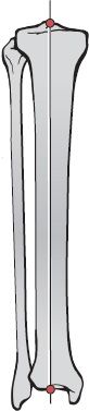
FIGURE 3-6 The mechanical axis of the tibia. (Reprinted with permission from Brinker MR, O’Connor DP. Principles of malunions. In: Bucholz, RW, Court-Brown CM, Heckman JD, et al., eds. Rockwood and Green’s Fractures in Adults. 7th ed. Philadelphia, PA: Lippincott Williams & Wilkins, 2010.)
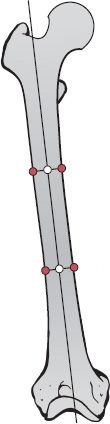
FIGURE 3-7 AP Anatomic axis of the femur. (Reprinted with permission from Brinker MR, O’Connor DP. Principles of malunions. In: Bucholz, RW, Court-Brown CM, Heckman JD, et al., eds. Rockwood and Green’s Fractures in Adults. 7th ed. Philadelphia, PA: Lippincott Williams & Wilkins, 2010.)
4. Lateral tibial anatomic axis—The lateral tibial anatomic axis is a series of mid-diaphyseal points parallel to the anterior cortex of the tibia. The lateral tibial mechanical and anatomic axes can be considered identical.
C. It is only necessary to differentiate between the AP anatomic femoral axis and the AP mechanical femoral axis. For deformity analysis, the lateral femoral axis, AP tibial axis, and lateral tibial axis can be considered to be a straight line formed by a series of mid-diaphyseal points, without differentiating between anatomic and mechanical methods.
VI. Joint Orientation—Normal joint orientation, as measured by the joint orientation angle, is also necessary but not sufficient for correction of deformity. The joint orientation angle is the angle formed by the intersection of the joint orientation line with the axis (either anatomical or mechanical) of the respective bone.
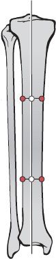
FIGURE 3-8 AP Anatomic axis of the tibia. (Reprinted with permission from Brinker MR, O’Connor DP. Principles of malunions. In: Bucholz, RW, Court-Brown CM, Heckman JD, et al., eds. Rockwood and Green’s Fractures in Adults. 7th ed. Philadelphia, PA: Lippincott Williams & Wilkins, 2010.)
1. AP plane
• Proximal femur
(a) Tip of the greater trochanter to the center of the femoral head (Fig. 3-9), or
(b) Longitudinal axis of the femoral neck (Fig. 3-10)
• Distal femur—A straight line tangential to the femoral condyles (Fig. 3-11)
• Proximal tibia—A straight line from the medial corner to the lateral corner of the tibial plateau (Fig. 3-12)
• Distal tibia—A line across the subchondral bone of the ankle mortise (Fig. 3-13)
2. Lateral plane
• Proximal femur—Neck–shaft angle is rarely used in the lateral plane.
• Distal femur—A line connecting the anterior and posterior extent of the distal femoral physis or the site of the closed physis (Fig. 3-14)
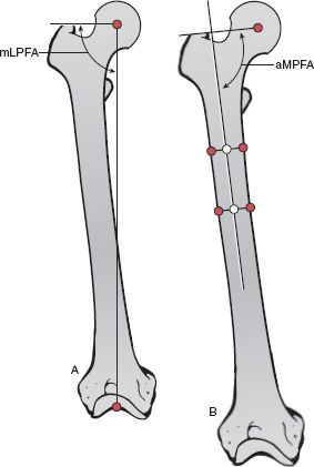
FIGURE 3-9 A. The joint orientation line from the tip of the greater trochanter to the center of the femoral head and the mechanical axis of the femur describe the mechanical Lateral Proximal Femoral Angle. B. The joint orientation line from the tip of the greater trochanter to the center of the femoral head and the anatomic axis of the femur describe the anatomic Medial Proximal Femoral Angle. (Reprinted with permission from Brinker MR, O’Connor DP. Principles of malunions. In: Bucholz, RW, Court-Brown CM, Heckman JD, et al., eds. Rockwood and Green’s Fractures in Adults. 7th ed. Philadelphia, PA: Lippincott Williams & Wilkins, 2010.)
• Proximal tibia—A line across the subchondral bone of the tibial plateau (Fig. 3-15)
• Distal tibia—A line between the anterior and posterior corners of the distal tibia (Fig. 3-16)
B. Joint Orientation Angles
1. The angles are abbreviated by five letters:
• The first letter is a lower case a or m, which designates anatomic or mechanical.
• The second letter is M (medial), L (lateral), A (anterior), or P (posterior), which designates the location of the angle with respect to the axis of the bone so that the normal value of the joint orientation angle is 90° or less. This nomenclature is not used for the femoral neck–shaft angle because of the longstanding traditional method of measuring the relationship between the femoral neck and shaft as the larger of the two supplementary angles at this site.
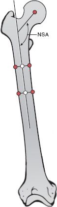
FIGURE 3-10 The longitudinal axis of the femoral neck and the anatomic axis of the femur describe the medial neck–shaft angle. (Reprinted with permission from Brinker MR, O’Connor DP. Principles of malunions. In: Bucholz, RW, Court-Brown CM, Heckman JD, et al., eds. Rockwood and Green’s Fractures in Adults. 7th ed. Philadelphia, PA: Lippincott Williams & Wilkins, 2010.)
• The third letter is P (proximal) or D (distal).
• The fourth letter is F (femur) or T (tibia).
• The final letter is A, the abbreviation for angle.
• Usually a (anatomic) or m (mechanical) is only used at the distal femur in which the aLDFA and mLDFA differ by 7°.
2. The normal values and ranges of normal are:
• AP plane (mechanical)
(a) Lateral proximal femoral angle (mLPFA) = 90° (range, 85° to 95°) (Fig. 3-9)
(b) Mechanical lateral distal femoral angle (mLDFA) = 88° (range, 85° to 90°) (Fig. 3-11)
(c) Medial proximal tibial angle (MPTA) = 87° (range, 85° to 90°) (Fig. 3-12)
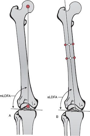
FIGURE 3-11 A. The distal femoral joint orientation line and the mechanical axis of the femur describe the mechanical Lateral Distal Femoral Angle. B. The distal femoral joint orientation line and the anatomic axis of the femur describe the anatomic Lateral Distal Femoral Angle. (Reprinted with permission from Brinker MR, O’Connor DP. Principles of malunions. In: Bucholz, RW, Court-Brown CM, Heckman JD, et al., eds. Rockwood and Green’s Fractures in Adults. 7th ed. Philadelphia, PA: Lippincott Williams & Wilkins, 2010.)
(d) Lateral distal tibial angle (LDTA) = 89° (range, 86° to 92°) (Fig. 3-13)
• AP plane (anatomic)
(a) Medial neck–shaft angle (NSA) = 130° (range, 124° to 136°) (Fig. 3-10)
(b) Medial proximal femoral angle (aMPFA) = 84° (range, 80° to 89°) (Fig. 3-9)
(c) Anatomic lateral distal femoral angle (aLDFA) = 81° (range, 79° to 83°) (Fig. 3-11
Related posts:

Stay updated, free articles. Join our Telegram channel

Full access? Get Clinical Tree


