Fig. 12.1
Attachment of the reference arrays
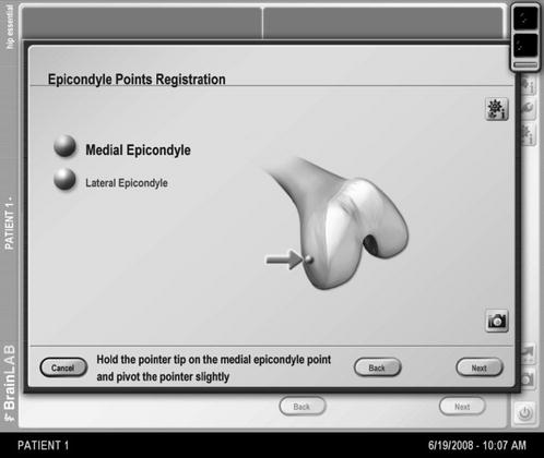
Fig. 12.2
Acquisition of the medial condyle point
Then the head-neck junction point is landmarked as well; this point is going to be used as a reference for the initial implant position (Fig. 12.3).
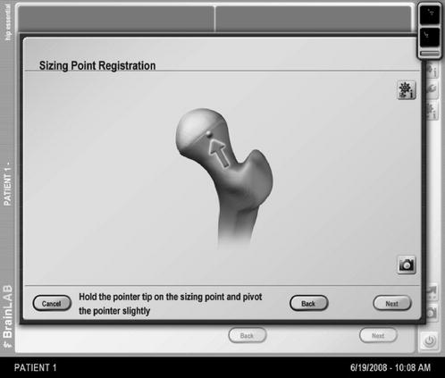
Fig. 12.3
Acquisition of the head-neck junction point
Now we work out the centre of rotation of the femoral head using the pointer to sample the femoral head. This point is used, in addition to the piriformis fossa point, to define the femoral axis and the axial plane (Fig. 12.4).
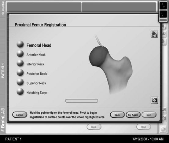
Fig. 12.4
Proximal femur registration
The calculation of the neck axis follows, making landmark points on the anterior (Fig. 12.5), superior, posterior and inferior neck. These points are also used to determine the notching zone. Additionally it is possible to define the superior notching zone, the most likely area of the femoral neck where notching occurs.
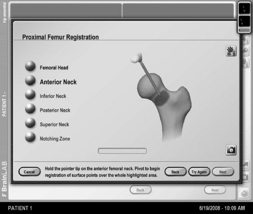
Fig. 12.5
Anterior neck registration
After all the necessary points have been acquired, the software creates a three-dimensional image of the femur, which has then to be verified by holding the pointer to the known landmarks. This assures that the location on the screen actually correlates with the actual pointer position (Fig. 12.6).
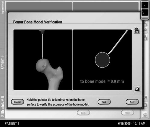
Fig. 12.6
Verification of femur model
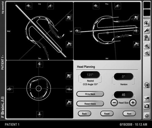
It is now possible to position the femoral head implant on the computer model and make very fine corrections in all three dimensions. Should this position the implant into a notching zone, this is indicated by red colour on the screen (Fig. 12.7).
 Smith-Petersen Approach and Lateral Position with Mini-Stem
Mini-Invasive Approach and Navigation in Total Prosthesis of the Hip
The Anterolateral Watson Jones Approach in Total Hip Replacement in the Supine Position
Anterior Approach for Total Hip Arthroplasty: Technique Without Fracture Table
Minimally Invasive Posterior Approach: Technical Evaluation, Initial Results and Follow-Up at Two Years
Navigated Modular Short-Stemmed Total Hip Arthroplasty by a Less Invasive Technique
Smith-Petersen Approach and Lateral Position with Mini-Stem
Mini-Invasive Approach and Navigation in Total Prosthesis of the Hip
The Anterolateral Watson Jones Approach in Total Hip Replacement in the Supine Position
Anterior Approach for Total Hip Arthroplasty: Technique Without Fracture Table
Minimally Invasive Posterior Approach: Technical Evaluation, Initial Results and Follow-Up at Two Years
Navigated Modular Short-Stemmed Total Hip Arthroplasty by a Less Invasive Technique


Fig. 12.7
Implant positioning
Related posts:
Smith-Petersen Approach and Lateral Position with Mini-Stem
Mini-Invasive Approach and Navigation in Total Prosthesis of the Hip
The Anterolateral Watson Jones Approach in Total Hip Replacement in the Supine Position
Anterior Approach for Total Hip Arthroplasty: Technique Without Fracture Table
Minimally Invasive Posterior Approach: Technical Evaluation, Initial Results and Follow-Up at Two Years
Navigated Modular Short-Stemmed Total Hip Arthroplasty by a Less Invasive Technique
Stay updated, free articles. Join our Telegram channel
Full access? Get Clinical Tree
