Fig. 13.1
The short-stemmed Metha prosthesis is coated on the proximal, metaphyseal area, which supports bony ingrowth and secondary stability. The tip is smooth and is only needed for primary stability. The neck is modular and can be chosen with variable degrees of antetorsion and CCD angles
Navigation System
We have been using an X-ray-free kinematic navigation system since 2001 (OrthoPilot, BBraun Aesculap, Tuttlingen, Germany), which has been developed and improved further in terms of software and hardware since then. The current technique employs passive rigid bodies whose position is detected by an infrared-emitting camera. The software allows control of the acetabular reamer and the final implant, taking into consideration inclination, anteversion, centre of rotation and depth for the cup. For the short-stemmed prosthesis, the femoral navigation was employed to control leg length, changes in offset and antetorsion and to predict the free range of motion in a safe zone to avoid dislocation. By providing this information, it helps to choose the right combination of modular neck and head out of the various possibilities.
Surgical Technique
Patient Positioning and Draping
The patient is placed supine on a standard radiolucent table. The navigation camera is placed on the contralateral side at the foot end of the table, at a distance of about 2 m. Prepping the operative field includes the ipsilateral iliac crest. Draping allows free movement of the entire leg and free palpation of both anterior superior iliac spines and the pubic symphysis. These landmarks are needed to determine the pelvic plane on which the calculation of the acetabular inclination and anteversion is based. Before starting the surgical approach to the hip, the ipsilateral iliac spine is identified and a 5 mm stab incision is made on the iliac crest about 4 cm dorsal to the anterior superior iliac spine. To avoid later irritations of the scar, the skin is tensed over the iliac crest, so that the scar will be caudal to the bone contour. A screw pin is fixed to the iliac crest on which the rigid body is adapted. The anatomic landmarks are then recorded with a pointer (Fig. 13.2).
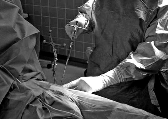
Fig. 13.2
After placing the rigid body in the iliac crest, the landmarks of the pelvis are palpated with a pointer to register the anterior pelvic plane
Surgical Approach
We have been using a modified and minimised anterolateral Watson-Jones approach [7]. The skin incision is about 8–10 cm long on the level of the anterior border of the greater trochanter. It extends from near the distal end of the greater trochanter to about 2–4 cm proximal of the tip of the trochanter. The fascia lata is displayed and split. In case of a trochanteric bursitis, the bursa is resected. The space between the vastus lateralis muscle and the gluteus medius is identified and split bluntly, a vessel occurring regularly in this place is cauterised. Then the capsule is exposed using two blunt curved Hohmann retractors, which are placed around the neck, and one pointed wide-bladed Hohmann retractor which is placed over the anterior rim of the pelvis. An oblique incision is made over the femoral neck from the medial proximal pelvic attachment of the capsule to the lateral distal femoral attachment. Two additional parallel incisions complete the Z-shaped opening of the capsule. The extent of this incision should allow dislocation of the femoral head, but can be extended to the lesser trochanter in case of contractures.
Before dislocating the hip, biomechanical data must be collected for the navigation system. A C-shaped clamp for the fixation of the femoral rigid body is placed on the femur slightly distal to the greater trochanter at the transition to the diaphysis of the femur. Placement of the clamp is facilitated by abducting the leg and rotating it slightly inward. Lately, we have been using a clamp holding device, which makes positioning more comfortable. First, we record the neutral position of the extended leg and then the centre of the patella and the ankle joint, both of which are recorded with the knee flexed at 90°. These data allow calculating the axis of the femur and the antetorsion of the femoral neck. To continue surgery, the rigid body can be removed from the clamp by a bayonet connection (Figs. 13.3 and 13.4a, b).
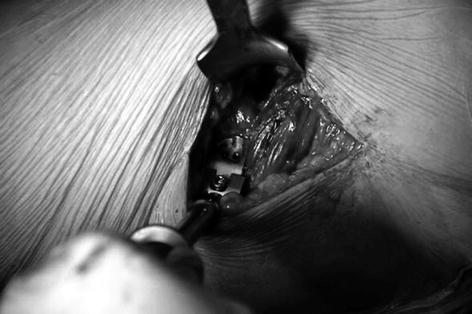
Fig. 13.3
A C-shaped clamp is placed on the femur, distal to the insertion of the gluteus muscle. The rigid body can be fixed and detached by a bayonet connection
Fig. 13.4
(a) Navigation screen for measurement of the initial neutral position. (b) Before dislocating the hip, the neutral position is registered with both rigid bodies attached. To go on with surgery, the rigid bodies can be removed temporarily
The hip is dislocated using a spoon-like lever that is placed between the femoral head and the acetabulum. With the hip dislocated, the resection level on the neck can be identified more clearly. The leg is placed slightly across the contralateral one. Resection of the femoral head is performed about 5 mm medial to the intertrochanteric line and at an angle of 50° to the femoral axis. This resection leaves the femoral neck somewhat longer than with standard stems. Only in very contract cases, the femoral neck is osteotomised in situ, and the head is then extracted using a corkscrew-like extractor (Fig. 13.5).
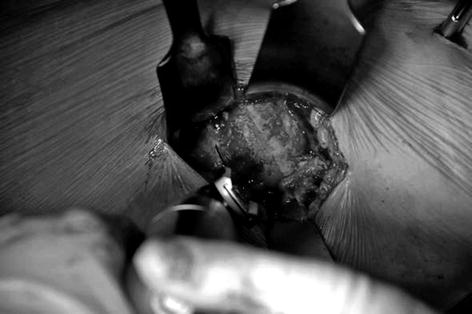
Fig. 13.5
The hip is dislocated to identify the line of resection more clearly, which should be in a 50° angle to the axis of the femur and about 5 mm medial to the trochanter-neck intersection
Acetabular Preparation
The acetabulum is now exposed using a bifurcate Hohmann retractor which is placed dorsal and distal to the acetabulum and a pointed wide-bladed curved Hohmann retractor, which is again placed over the anterior acetabular rim. Occasionally the capsule needs to be retracted which can be done by sutures. The deepest point on the medial wall of the acetabulum is then palpated and recorded using a pointer so that the navigation system can provide information on the depth of reaming and on medial or lateral displacement of the centre of rotation in relation to the original hip centre. The inclination and anteversion of the acetabulum is registered by a trial cup of approximately the diameter of the final cup. This information is displayed on the navigation screen.
Reaming usually starts with a reamer one size smaller than the trial cup. The display of the navigation system provides information on which direction to ream, based on the inclination and anteversion and on the depth relative to the point of the medial wall palpated prior to reaming. Additional information is given about changes of the centre of rotation towards a proximal/distal, medial/lateral and anterior/posterior direction. This helps to influence the final cup position when dysplastic or other deforming conditions have to be corrected. When a good position is achieved and the whole acetabular surface is freed of cartilage and the cortical bone is roughened, so that fine bleeding is visible, the position is recorded (Fig. 13.6a, b).
Fig. 13.6
(a) Navigation screen for reamer navigation. (b) The navigation system provides information on the direction and depth of reaming
The acetabular implant is placed and impacted with the navigation system giving information on its position relative to the acetabulum. Our aim is to place the cup at 45° inclination and 15° anteversion, based on the data given by Lewinnek et al. [8] for a “safe zone”. When press fit of the implant is achieved in the desired position, the ceramic inlay is inserted and impacted, and the new centre of rotation is recorded with a ball-headed device the size of the chosen head (Fig. 13.7a, b).
Fig. 13.7
(a) Navigation screen for navigating the cup. The navigation system provides information on the direction and depth of reaming. (b) The final cup position can be controlled on the screen of the navigation system
Femoral Preparation
The leg is now placed in a 90° external rotation and maximum adduction. The bifurcate Hohmann retractor is placed under the greater trochanter in order to lever it above the iliotibial band, and another more curved bifurcate retractor is placed behind the posterior aspect of medial femoral neck. The resection plane is now visible in its complete circumference. The femoral preparation starts with a bent awl. The point of insertion of the awl is close to the centre of to the neck, first directed towards the lateral femoral cortex and then along the diaphysis. Care has to be taken to prevent perforation of the femoral cortex. A second awl, slightly thicker than the first, is introduced in the same manner. The awls already follow the antetorsion of the femoral neck.
Related posts:
 Smith-Petersen Approach and Lateral Position with Mini-Stem
Mini-Invasive Approach and Navigation in Total Prosthesis of the Hip
The Anterolateral Watson Jones Approach in Total Hip Replacement in the Supine Position
Anterior Approach for Total Hip Arthroplasty: Technique Without Fracture Table
Minimally Invasive Posterior Approach: Technical Evaluation, Initial Results and Follow-Up at Two Years
Navigation and the Square Angle Pointer in Hip Resurfacing
Smith-Petersen Approach and Lateral Position with Mini-Stem
Mini-Invasive Approach and Navigation in Total Prosthesis of the Hip
The Anterolateral Watson Jones Approach in Total Hip Replacement in the Supine Position
Anterior Approach for Total Hip Arthroplasty: Technique Without Fracture Table
Minimally Invasive Posterior Approach: Technical Evaluation, Initial Results and Follow-Up at Two Years
Navigation and the Square Angle Pointer in Hip Resurfacing
Stay updated, free articles. Join our Telegram channel

Full access? Get Clinical Tree


