Materials in Hip Surgery
Metals for Cemented and Uncemented Implants
Warren O. Haggard, Joel D. Bumgardner and Phillip J. Andersen
Key Points
Introduction
Hip arthroplasty started with the implantation of interpositional layers of various biological materials in the joint, including fascia, skin, and even pig bladder.1 In the 1930s, these materials were replaced with shells of stainless steel and an early cobalt-chromium alloy, Vitallium.1,2 The use of metals in interpositional and total hip joint replacement implants (THAs) continued through the 1930s and 1940s until the 1950s, when British orthopedic surgeon Sir John Charnley developed the lower friction bearing couple and enhanced fixation for THA. With improved survivorship of this procedure, stemming from the designs of Charnley, among others, total hip replacement has been referred to as “the orthopedic procedure” of the last century.1 Improved survivorship for all THA systems resulted from enhanced surgical techniques, improved implant designs, and more advanced materials and processing. The transition from stainless steel to cobalt-chromium (Co-Cr), titanium (Ti), and advanced stainless steel alloys has continued efforts to improve THA. This chapter provides a brief overview of the structure, mechanical properties, strengthening mechanisms, and advantages and disadvantages of metals used in THA.
Basic Science
The performance of metals and alloys used in orthopedic implants and devices depends in part on atomic bonding and structures for bulk properties, as well as surface properties for material-host interactions. In this chapter, we review the bonding and crystal structure of metallic implant materials as they relate to the bulk physical and mechanical properties of these materials, along with the surface properties of orthopedic metals, as they affect corrosion resistance within the body.
Metallic Structures
Metals and alloys derive their classical characteristics of formability, toughness, and high heat and electrical conductance from primary bond formation called metallic bonding. In metallic bonding, the atoms share their outermost (valence) electrons, which create a “sea” or “cloud” of electrons surrounding the positive nuclear core of the metal atoms (Fig. 6-1). Charge neutrality is maintained because the negative electrons act as a thick paste between positive nuclear cores. Because of delocalization of the electrons around atom cores, metallic bonds are often referred to as nondirectional and nonspecific, and the mobility of the electrons in the metal is what leads to their high heat and electrical conductivity. Additionally, the delocalization enables individual metal atoms or planes of atoms to “slide” relatively easily with respect to each other, which gives metals and alloys their typical ductile and malleable characteristics.
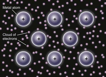
Figure 6-1 Schematic of metal bonding. Outer shell electrons are shared between positively charged nuclear cores of metal atoms, such that the atoms are bonded to each other via a “sea” or “cloud” of electrons.
Nondirectional and nonspecific bonding also allows metal atoms to arrange themselves in regular, long-range, repetitive patterns or crystal structures. Amorphous materials lack long-range order, although some short-range structures may be present. The crystalline patterns or structures are represented by three-dimensional space lattices based on a repeating unit cell. There are 14 distinct space lattices, called Bravais lattices, based on the relative lengths of the unit cell edges, the angles between edges, and the position of atoms within the cell. The atoms in implant metals are most commonly arranged in cubic or hexagonal structures (Fig. 6-2). In the body-centered cubic (BCC) arrangement, an atom is located in the center and at each corner of the cube. Iron, molybdenum, chromium, and tantalum are common metals that arrange in the BCC crystal structure. In the face-centered cubic (FCC) arrangement, an atom is located at each corner of the cube, and an atom is present in the center of each face of the cube. Aluminum, nickel, platinum, and silver are common metals that arrange in the FCC crystal structure. In the hexagonal, close-packed (HCP) arrangement, an atom is located at each corner of the hexagon and in the center of the top and bottom faces; three atoms are found within the center. Titanium, cobalt, and zinc arrange in the HCP structure. Using a hard-sphere model and simple geometry, the density of atoms per unit cell volume or the packing factor may be calculated as 0.76 for FCC and HCP unit cells and 0.68 for BCC unit cells. These crystalline arrangements are important for overall mechanical and corrosion properties and the ability of metals to be mixed to form alloys.
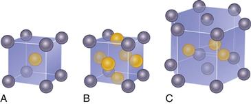
Figure 6-2 Schematic of crystal lattice systems common to implant alloys. A, Body-centered cubic (BCC). B, Face-centered cubic (FCC). C, Hexagonal close packed (HCP).
Defects in Crystal Structures and Alloying
Although metal atoms readily assume crystalline structures, defects arise in the crystal arrangements as a result of the natural thermodynamics of crystal formation. The two major types of defects are point defects and line defects.
Point defects involve missing atoms or vacancies in crystal lattice positions, or impurity atoms, which can occupy spaces in between atoms in the lattice structure (i.e., interstitial positions) or in a normal lattice position (i.e., substitutional positions) (Fig. 6-3). The most common line defects are dislocations. Dislocation defects occur as the result of uneven completion of rows of atoms in a crystal, such that an extra half-plane of atoms appear in regular packing arrangements (Fig. 6-4). Grain boundaries also arise because of the thermodynamics of crystal formation and occur where two growing crystals meet but at slightly different orientations such that crystal lattices do not match up (Fig. 6-5). Except under some very special conditions, all metals and alloys have a grain structure.

Figure 6-3 Schematic of point defects in metal crystal structures.
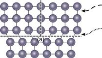
Figure 6-4 Schematic of a dislocation (⊥) in metal crystal structures. a, Increased lattice strain. This makes it relatively easy to break and re-form bonds, one at a time, along the edge of the dislocation (dashed arrow) as compared with a complete plane of atoms (hyphened arrow) and results in the ability of metals to be deformed at lower forces than might be predicted for a perfect crystalline metal.
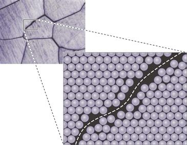
Figure 6-5 Schematic of grain boundary highlighting the mismatch in crystal lattices due to small changes in orientation between grains.
In general, the presence of defects greatly reduces the strength of crystal structures from theoretical values based on perfect, defect-free crystal structures. In the case of dislocation defects, the energy required to break the metallic bond along the plane of the dislocation is much less than the energy required to break all of the bonds on an entire plane of a perfect crystal lattice. The result is that a half-plane of atoms is moved and the metal is deformed in response to a lower mechanical force by breaking and reforming a line of bonds, one or a few at a time, as compared with the force needed to break bonds in an entire plane of atoms (see Fig. 6-4).
However, the purposeful introduction of interstitial or substitutional point defect atoms into crystal structures creates lattice strain, which makes it harder for dislocations to move, thus increasing the stress required to cause permanent changes in shape (i.e., the yield strength of the material). This is the basis of alloying metals together to impart greater strength and related properties. Interstitial alloys are formed when solute atoms are much smaller than the solvent atom (e.g., B, C, N, O are often used to form interstitial alloys with Fe, Co, and Ti metals). For example, enhanced grades of stainless steel are manufactured for orthopedic applications in which nitrogen has been added to iron alloys to occupy interstitial sites in the FCC lattice. Substitutional alloys are favored when the following conditions, also known as the Hume-Rothery rules, are satisfied:
• The difference in size of atomic radii of the solvent and solute atoms is less than 15%.
• Both elements have the same crystal structures (especially with a large proportion of solute atoms).
• Atoms exhibit similar electronegativities (i.e., close to each other in the periodic table).
These rules are a result of the fact that if substitution necessitates a large change in the size of an atom in the matrix, the crystal structure, or the lengths and strengths of the bonds present, there will be too much strain in the lattice for atoms to remain in the normal equilibrium positions. In cobalt-chromium alloys used to manufacture hip prostheses, chromium can substitute into lattice positions normally occupied by cobalt atoms.
When these rules are not satisfied, some segregation of the atomic species into two or more phases is seen. For example, the Ti-6Al-4V (Titanium [Ti], Aluminum [Al], Vandium [V]) alloy is a two-phase alloy containing an aluminum-rich HCP phase (α) and a vanadium-rich BCC phase (β).
Strengthening Mechanisms
In general, metals can be strengthened by making it more difficult for dislocations to move through the crystal lattice. This can be done in several basic ways, including developing fine grains in the metal, adding alloying elements that distort the crystal structure (solid solution strengthening), deforming the metal at low temperatures to increase the number of dislocations within the crystal lattice (work hardening or cold working), and creating fine dispersions of a second phase to interfere with dislocation motion (heat treatments to “age” the material are a common way to do this).
Grain Size Effects
In general terms, a metal with small grains is stronger than the same metal with coarse grains at temperatures of interest for implants. At room temperature, grain boundaries are significant barriers to dislocation motion. A classic description of this effect is given by the Hall-Petch equation: σy = σo + kD−{1/2}, where σY is the yield stress of the metal, σo is a frictional stress required to move dislocations, k is the Hall-Petch slope, and D is the grain size.3 A variety of metals, including some stainless steels3 and commercially pure (CP) titanium (Ti),4 exhibit yield strength versus grain size relationships that follow this relationship.
Solid Solution Strengthening
High-purity metals typically are soft and ductile, and are very expensive to produce. This combination means that the uses for high-purity metals are limited. Metals used for orthopedic implants are alloys that have a major constituent (also referred to as the solvent) and a number of alloying ingredients (the solute atoms). Some of these elements are present at low levels because of impurities in the raw materials, but the main alloying elements are added for specific reasons (e.g., Cr is added to stainless steel and cobalt base alloys to enable formation of a passive film for corrosion protection and to increase strength). In general, the atoms of metallic alloying elements such as Cr, Ni, and Mo replace solvent atoms at random sites within the matrix. Because the size of atoms of the substrate and of alloying elements is not the same, distortions occur within the crystal lattice, which increase resistance to dislocation motion. As a result, strength increases but ductility decreases.
Small atoms such as nitrogen, carbon, and oxygen fit into the interstitial sites. The addition of interstitial alloying elements has a very large effect on the properties of some alloys used in medical devices. Nitrogen additions to stainless steel greatly increase strength and improve corrosion resistance. The strength of CP titanium also increases dramatically with iron and oxygen content. Whereas the tensile strength of grade 1 CP Ti (maximum, 0.18% O and 0.20% Fe) is only 240 MPa, grade 4 CP Ti, with more than twice the interstitial content (0.40% O and 0.50% Fe), has a strength of 550 MPa.5
Work Hardening/Cold Working
The response of metals to deformation depends on the temperature at which the deformation takes place. Deformed metallic structures contain large numbers of dislocations, which increase the total energy of the system. This energy provides a driving force to form new grains with low numbers of dislocations, but enough atomic mobility must be present to allow the new grains to form. This requires elevated temperatures. The temperature at which new grain formation occurs is referred to as the recrystallization temperature, but this usually is not a specific fixed temperature. The recrystallization temperature depends primarily on the alloy in question, but other factors (e.g., amount of deformation, hold time at temperature, presence of second-phase particles) influence recrystallization behavior. For Ti-6Al-4V, recrystallization temperatures are in the range of 800° C to 850° C.4
When metals are deformed at “low” temperatures (below the recrystallization temperature), additional dislocations are formed within the crystal lattice. With an increase in the number (or density) of dislocations within the lattice, interactions occur between dislocations, causing them to become less mobile. This increases the strength of the metal while decreasing its ductility. Work-hardened metals are often described by the amount of deformation that was involved in the production of the material (e.g., a 30% cold-worked, stainless steel). Work hardening (also known as cold working) is routinely used to increase the strength of stainless steel and cobalt base alloys for a variety of applications. In the case of the austenitic stainless steels used as implant materials (316L, BioDur 108, etc.), initial strengthening is attained through the addition of alloying elements to the iron substrate (termed solid solution alloying). Additional increases in strength occur only through work hardening treatments. If a work-hardened alloy is heated sufficiently (i.e., by processes such as welding or sintering a porous coating onto the surface), recrystallization will take place, and the new metal grains that form will not be in a work-hardened state. Consequently, any metal within the recrystallized region will have significantly reduced strength and increased ductility. Table 6-1 shows the impact of work hardening on the strength and ductility of several common implantable alloys.
Table 6-1
Mechanical Properties of Some Annealed and Cold-Worked Implantable Alloys

Precipitation Dispersion Strengthening
Alloys may be strengthened by a mechanism termed precipitation dispersion, which involves the formation of a large number of fine precipitates within the microstructure to increase resistance to the motion of dislocations, thus increasing strength. The necessary precipitation reactions are not possible in every alloy system. For example, the austenitic stainless steels, such as 316L, do not respond to this process because no desirable precipitates can be formed. In practice, precipitation dispersion strengthening generally is performed by rapidly cooling (quenching) a metal alloy that has been held at an elevated temperature (this is often referred to as a solution treatment), followed by a lower temperature exposure (the aging treatment). At elevated temperatures, alloying elements are in a solid solution within the alloy. Rapid cooling prevents the alloy from forming the structure that would be formed under slower, more equilibrium conditions. When the quenched alloy is then held at an intermediate temperature, small particles of second phases can form (precipitate) within the solution. The solution and aging treatment temperatures depend on the alloy in question. This approach can be used for β-titanium alloys, such as Ti-15Mo, cold-worked Co-Cr alloys (MP35N), and several of the stainless steels used to produce surgical instruments.
Orthopedic Implant Alloy Compositions and Microstructures
The major types of alloys used in orthopedics are the stainless steel, cobalt-chromium alloys (Co-Cr) and titanium (Ti) alloys (Table 6-2).
Table 6-2
Composition of Some Common Orthopedic Implant Alloys
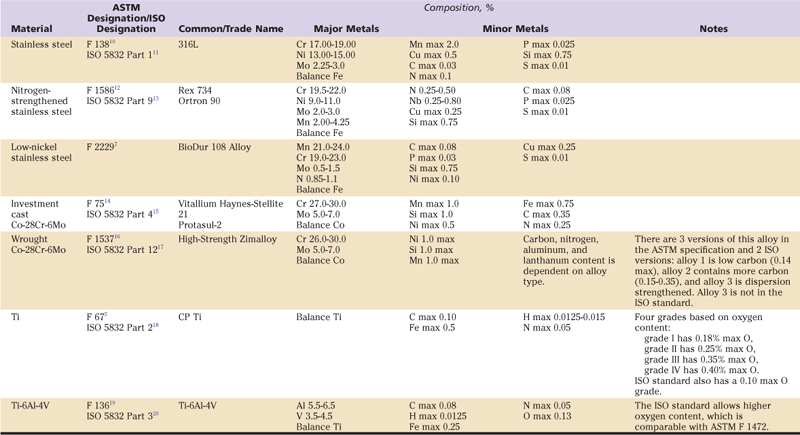
The most common type of stainless steel is 316L. It is a single-phase, iron-base alloy in an FCC crystal arrangement called the γ-phase or austenite. The “L” designation refers to the low (less than 0.03 wt%) carbon content of the alloy in comparison with the conventional 316 grade (0.08% C). The addition of chromium enables the development of a corrosion-resistant, chromium-oxide surface layer, and the addition of molybdenum enhances the oxide’s resistance to corrosion, especially in chloride environments such as the body. Nickel is added to help stabilize the austenitic structure. The single-phase, stainless steel structure, along with the more densely packed FCC crystal arrangement, tends to provide greater corrosion resistance than the BCC-based stainless steels. The low carbon content also promotes corrosion resistance by preventing the formation of chromium carbides, which precipitate at grain boundaries and reduce corrosion resistance. Steels in which chromium carbides have formed are “sensitized” and may fail from corrosion-assisted fractures that arise at the weakened chromium-depleted grain boundaries.
The austenitic nitrogen-manganese–strengthened stainless steel known by the names Ortron 90 and Rex 734 alloy is in use to produce hip stems outside of the United States. This alloy can be processed to offer higher fatigue strength and corrosion resistance than 316L. A similar stainless steel, BioDur 108, is a low-nickel, austenitic alloy that has been developed to address concerns over the potential of nickel ions released from corrosion products of 316L to induce metal hypersensitivity reactions. In this low-nickel alloy, 0.85% to 1.10% nitrogen is added to stabilize the austenitic microstructure and to maintain high strength and corrosion resistance. The addition of large amounts of manganese (21%-24%) also aids in austenite stabilization.8,9
The cobalt (Co)-based alloy most commonly used for hip prostheses contains approximately 28 weight % chromium (Cr) and 6 weight % molybdenum (Mo). The use of cobalt-based alloys dates back to the 1930s, when this material was used by Smith-Peterson as an implant to cover the femoral head and prevent bone-to-bone contact. Several variations of the chemical compositions of this alloy are known; different manufacturing techniques result in significantly different mechanical properties.
The initial Co-Cr-Mo implants were made by investment casting. This process starts with a wax replica of the desired product, which is dipped in a ceramic slurry and then dried. With multiple applications of the ceramic coating, sufficient strength is built up for the ceramic shell to act as a mold without internal support. At this stage, the wax is melted out and the mold is preheated and then filled with molten metal to form an implant. After the metal solidifies, the mold materials are removed and the cast parts are further processed to achieve the dimensions and finish of the final product.
The resulting microstructure of the cast Co-Cr-Mo alloy is complex and is dependent on exact casting conditions, but it generally can be described as a cobalt-rich matrix (α-phase) with precipitated carbides (primarily M23C6, where M represents Co, Cr, or Mo). The carbides contribute to the alloys’ excellent wear resistance. The casting process also results in an alloy with large grains comprising approximately 85% α-phase and 15% carbides. Casting conditions must be closely monitored to avoid casting defects, such as porosity and entrapment of foreign materials. Many cast products receive additional heat treatments to alter the carbide morphology; the use of hot isostatic pressing (HIP’ing) to close internal porosity is also common.
Stronger femoral hip stems can be produced from the same basic Co-Cr-Mo alloy by using forging or by machining parts from warm-worked bar stock. Forging involves using dies with shaped cavities that are mounted in various types of presses or hammers. The shape of the final die cavity approximates the desired product shape. Metal bars are deformed in the die cavities by forces applied by the press. In most cases, the metal is heated before it is deformed, and a series of cavities must be used because the desired shape cannot be formed in a single step. Conventional bar stock is produced from large cast ingots through a series of deformation processes (open die forging, rolling, etc.) at elevated temperatures. These processes lead to much finer grain size than as-cast metals, improved chemical homogeneity, and, in many alloys including Co-Cr-Mo, the development of a complex, work-hardened structure. The term wrought is often applied to metal products that start as large cast ingots and are worked down to usable sizes through processes such as forging or rolling. Thus, the microstructures of cast and wrought Co-Cr-Mo alloys are dramatically different, as can be seen in Figure 6-6. The mechanical properties of wrought or forged Co-Cr-Mo are substantially greater than the cast material.

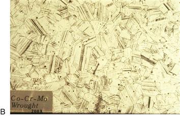
Figure 6-6 Microstructures of Co-Cr-Mo alloy in (A) as-cast and (B) forged conditions. Note the large carbides (dark particles) in the as-cast material. The forged specimen in this example is made with a Co-Cr-Mo composition that uses small additions of nitrogen instead of carbon. The grain size of the forged specimen is much smaller than that of the cast material. (Original magnification ×200.)
An alloy known as MP35N was once used widely to produce femoral hip stems, but it is no longer widely used for this application. The nominal composition of the alloy is 35 weight % Co and nickel (Ni), 20 weight % Cr, and 10 weight % Mo. This alloy can be processed to very high fatigue mechanical strengths, but it has been replaced by forged Co-Cr-Mo and Ti alloy hip stems.
The major types of titanium alloys are commercially pure (CP) Ti (α or HCP structure), α+β alloys such as Ti-6Al-4V, and β alloys such as Ti-12Mo-6Zr-2Fe. The crystal structure of Ti alloys depends on composition and processing parameters, such as the amount of deformation, the temperature at which deformation takes place, and the cooling rate after forging. In the case of Ti-6Al-4V, the addition of the alloying elements aluminum and vanadium has a stabilizing effect on the α- (HCP) structure and the β- (BCC) structure, respectively. Hence, the Ti-6Al-4V alloy is called an α+β alloy, in which the relationship of the α and β phases to each other depends on details of the processing methods used to produce the material. Carefully controlled hot working and annealing processes result in fine dispersion of the α and β phases, which results in superior, high-cycle fatigue properties.
CP Ti is commonly used to produce acetabular components; the higher-strength α+β or β alloys are used to produce femoral hip stems. Ti has a high affinity for oxygen, and CP Ti actually may be thought of as a single-phase alloy of titanium and oxygen, with the oxygen atoms occupying interstitial sites in the HCP lattice of the α phase. The high affinity of titanium for oxygen also results in the formation of a titanium oxide surface layer, which provides all Ti alloys with their exceptional corrosion resistance. The oxygen content of the alloy has a great impact on mechanical properties and forms the basis of the four grades of CP Ti, which range in oxygen content from 0.18% to 0.40% (see Table 6-2). CP Ti is commonly used to produce acetabular components; the higher-strength α+β or β alloys are used to produce femoral hip stems.
Stay updated, free articles. Join our Telegram channel

Full access? Get Clinical Tree


