Fig. 14.1
(a) Anterior and lateral radiograph after TKR showed the tibial component was placed in 4° varus in relation to tibial axis. (b) Femoral and tibial component loosening after 10 years of follow-up
In terms of coronal alignment, the surgeon should strive for 3° valgus-varus alignment in relation to the mechanical axis. Outside this range is associated with more rapid failure and less satisfactory functional results after TKR.
To reduce this error, computer-assisted navigation systems have been developed. It has been shown that navigated TKR implantation leads to a more accurate and precise positioning of the TKR [8, 9]. However, with regard to clinical outcomes, no clinically significant difference has been reported [10–12]. In contrast, Kim et al. demonstrated that the computer-assisted technique did not increase the precision of component placement over that achieved by the conventional technique [13]. In response to this controversy, a systematic review of literature from 1990 to 2007 on 29 studies of computer-assisted versus conventional TKR found that mechanical axis alignment of greater than 3° occurred in 9.0 % of computer-assisted versus 31.8 % of conventional TKR [14]. A meta-analysis of 29 quasi-randomized/randomized controlled trials and 11 prospective comparative studies comparing 2,827 imageless computer-assisted versus 2,647 conventional TKR showed that postoperative limb axis of greater than 3° occurred in 11.04 % of computer-assisted versus 27.33 % of conventional TKR [15]. In their report (Table 14.1), outliers of the component alignment of 3° or more were 10.4 % in the navigated group and 27.71 % in the conventional group in the coronal plane of the femur, 12.75 % in the navigated group and 40.50 % in the conventional group in the sagittal plane of the femur, 3.97 % in the navigated group and 21.37 % in the conventional group in the coronal plane of the tibia, and 20.96 % in the navigated group and 44.68 % in the conventional group in the sagittal plane of the tibia.
Table 14.1
Outliers of component alignment implanted with navigation or conventional technique
Outliers of component alignment (%) | ||
|---|---|---|
Navigated group (n = 2,827) | Conventional group (n = 2,647) | |
Mechanical axis (>3°) | 11.04 | 27.33 |
Coronal plane of femoral component (≧3°) | 10.4 | 27.71 |
Sagittal plane of femoral component (≧3°) | 12.75 | 40.5 |
Coronal plane of tibial component (≧3°) | 3.97 | 21.37 |
Sagittal plane of tibial component (≧3°) | 20.96 | 44.68 |
Computer-assisted TKR significantly reduces the outliers in terms of TKR tibial and femoral component position in the sagittal and coronal plane.
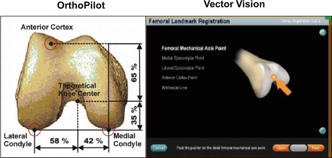
The authors similarly reported on a CT-free navigation system that significantly improved the accuracy of implantations in relation to the mechanical axis and achieved an early and midterm clinical outcome equivalent to that of a manual group [16–18]. In these reports, “black boxes” for the navigation system were also advocated. One such factors is the different definitions of the bony landmarks, especially the knee center in the sagittal plane, where the recommendations of each company’s engineer may be different. Two different CT-free navigation systems (Orthopilot ver. 4.2, Aesculap, Tuttlingen, Germany, and Vector Vision®, DePuy-Brainlab, Heimstetten, Germany) were used for comparison of prosthetic alignments. Although the parameters, especially in the coronal plane, showed no statistical differences between the two groups, the results showed a more flexed position of the femoral implant by 4.0° on average in the Orthopilot group compared to the Vector Vision group. This discrepancy may be explained by the differences in the determined knee center. In the Vector Vision navigation system, knee center is defined by the surgeon’s registration point, a point 1 cm anterior to the distal end of intercondylar notch. In contrast, in the Orthopilot navigation system, the knee center is determined by several registration points of a theoretical knee center; it is a point identified 65 % posteriorly on the line between the anterior cortex and the most prominent point of the posterior medial femoral condyle. Therefore, the difference in the definition of the knee center between the two navigation systems leads to a different mechanical axis: the mechanical axis 1 in the Vector Vision group and mechanical axis 2 in the Orthopilot group (Fig. 14.2). In the measurement of 200 lateral radiographs of volunteers, Chung et al. [19] recently reported that the angle between mechanical axis 1 and mechanical axis 2 was 3.0° on average, supporting the authors’ results.


Fig. 14.2
Knee center is defined by the surgeon’s registration point in the Vector Vision navigation system, while the knee center is determined by several registration points of a theoretical knee center in the Orthopilot® navigation system
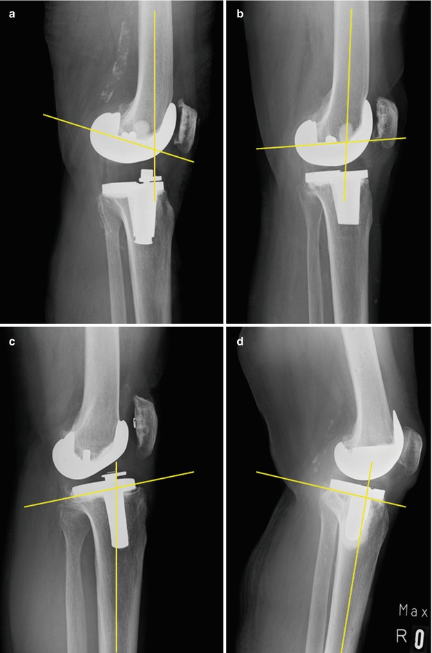
Even with the use of the navigation systems, surgeons should take implantation, especially in sagittal plane, into account, avoiding excessive extension and flexion of the femoral component and anterior slope and excessive posterior slope of the tibial component (Fig. 14.3).


Fig. 14.3
Femoral and tibial component malpositions. (a) Femoral component is placed in excessive flexion, causing flexion contracture and possible post/cam impingement. (b) Femoral component is placed in excessive extension, resulting anterior notching in extension. (c) Tibial component is placed in excessive posterior slope. (d) Tibial component is placed in anterior slope
As a new tool for properly aligning prostheses, patient-specific instrumentation using MRI or CT imaging to generate patient-specific guides that can be used intraoperatively to control all 6 degrees of freedom of component alignment has recently been developed. The goals of the patient-specific instrumentation technology are to customize disposable blocks unique to each patient’s anatomy in an attempt to increase the accuracy of the bone preparation and eliminate outliers of component malpositioning. There are several commercially available patient-specific guides available that use one of the two basic alignment goals based on either restoring the mechanical alignment [3, 20] or restoring kinematic alignment [21]. In the mechanical axis model, component placement is perpendicular to the mechanical axis of the tibia and parallel to the epicondylar axis of the femur (distal femoral resection in 5–8° valgus) [3, 20]. In the kinematic model, the surgeon aligns components with the flexion-extension axis of the femur, which passes through the center of the medial and lateral condyles and deviates from the epicondylar axis by an average of 5° and as much as 11° [21]. Kinematic alignment was developed with the goal of improving patients’ clinical outcomes by restoring the prearthritic alignment of the limb and knee and not releasing the collateral or retinacular ligaments.
Commercially available patient-specific guides have been introduced to improve position of TKR. These are either based on restoring the mechanical alignment or kinematic alignment. However, the clinical value of such patient-specific guides is yet to be shown.
Recently, Nunley et al. [22] retrospectively evaluated 150 primary TKRs performed for osteoarthritis: Group 1 (n = 50) conventional instrumentation; Group 2 (n = 50) patient-specific instrumentation restoring the mechanical axis; and Group 3 (n = 50) patient-specific instrumentation restoring the kinematic axis. The results showed that the mean femorotibial angle differed between the groups: Group 1 had the greatest varus mean alignment and most varus outliers. The mean hip-knee angle was similar between Groups 1 and 2, with Group 3 having greater valgus mean alignment and the most valgus outliers. For the zone of the mechanical axis, Groups 1 and 2 had similar percentages of outliers (40 % versus 32 %), whereas Group 3 had a greater number of outliers (64 %) that were valgus. Based on the results, they concluded that additional studies are needed to determine whether patient-specific instrumentation improves clinical function or patient satisfaction and whether the routine use can be justified in primary TKR.
14.3 Malrotation of TKR
Clinical outcomes following TKR are also associated with rotational alignment. Numerous authors have pointed out a relation between mal- rotation of the femoral component and patellar maltracking, anterior knee pain, femoro-tibial flexion instability, and premature wear of the polyethylene inlay in TKR [23, 24].
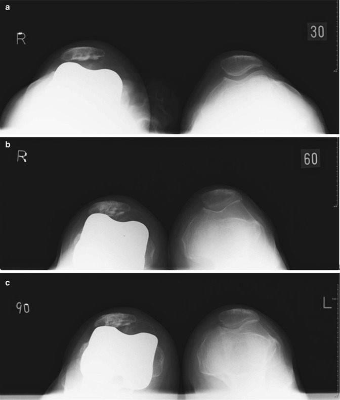
In one case of a patient who consulted the authors’ institution after initial treatment at another hospital, for example, internal rotation of the femoral component resulted in patellar maltracking and patellar dislocation (Fig. 14.4). Several authors [25, 26] believe that an excessive internal rotation of the femoral component of more than 3–6° may lead to the aforementioned chronic symptoms. The Whiteside line, the posterior condyle axis, and the transepicondylar axis are used as anatomical landmarks for determining femoral component rotation. Assessment of femoral rotation with respect to these landmarks varies between studies, making comparison difficult [27]. A meta-analysis by Cheng et al. [15] showed that the lower limb axis and component orientation were improved in the coronal and sagittal plane but not improved in the rotational alignment even with the use of an imageless computer-assisted navigation system. On the other hand, femoral component rotation of the TKR can be determined by two techniques: a balanced gap technique as well as a measured resection technique. Some investigators favor a measured resection technique in which bony landmarks (femoral epicondyles, posterior femoral condyles, or the anteroposterior axis) are the primary determinants of femoral component rotation [28]. Others recommend a gap-balancing methodology in which the femoral component is positioned parallel to the resected proximal tibia with each collateral ligament equally tensioned [29]. Responding to such debate, Seon et al. have reported more consistent equalization of extension and flexion gaps with the use of a computer-assisted gap-balancing technique, compared with the conventional measured resection technique [30]. In contrast, in the comparison between navigation-assisted measured resection and navigation-assisted gap-balancing technique, some surgeons reported a better restoration of the joint line position in the navigation-assisted measured resection technique despite no differences in short-term clinical outcomes [31].


