Chapter 11 Kinesiology: An Essential Approach toward Understanding the Chiropractic Subluxation
Kinesiology, spinal motion segment, three-joint complex, six degrees of freedom, coupled motion, hypomobility, hypermobility, aberrant motion, instability, instantaneous axis of rotation
After reading this chapter you should be able to answer the following questions:
| Question 1 | What contributes to the coupled motion of spinal motion segments? |
| Question 2 | What is the function of muscle spindles? |
| Question 3 | What are the stages of spinal joint degeneration and how do they affect segmental spinal motion? |
Kinesiology is the study of movement (kinesis—to move; ology—to study). Under this broad definition, kinesiology includes the specialized areas of biomechanics, motor control, and exercise physiology. Although each of these areas has relevance to the student and doctor, a detailed discussion of each area is beyond the scope of this chapter. Instead we will focus our discussion of kinesiology on the study of human movement with particular interest in the anatomic and clinical biomechanical interactions of the musculoskeletal system. The purpose of limiting our definition is so that we may better understand articular motion (i.e., kinematics) and the forces acting at the motion segment (i.e., kinetics). Kinematics describes the position and motion of the body (i.e., limb, trunk, joint, spinal motion segment) without consideration of the forces acting on the body. Kinematics is quantified using measurements for displacement (e.g., range of motion), velocity, and acceleration. Kinetics is the description of forces that maintain equilibrium in the body or that produce, stop, or modify body motion. In application, these principles of motion and force are used therapeutically through the chiropractic adjustment to normalize, restore, and enhance function in the patient’s interest (Table 11-1).
Table 11-1 Criteria for the Kinesiologic Evaluation of the Subluxation
| Kinesiologic descriptors of normal joint function | Kinesiopathology: criteria for subluxation* | Symptoms related to the subluxation |
|---|---|---|
| Kinetic | ||
| Local and/or regional: | ||
| Kinematic | ||
* The term subluxation is characterized and defined according to principles of kinesiology. In this model, contact between joint surfaces is assumed to remain partially intact and changes in joint function are mechanically related to a change in function of artic-ular and periarticular soft tissue structures.
Chiropractic students and the profession1 often use the term kinesiology in reference to Applied Kinesiology Technique (AK). The academic discipline of kinesiology, however, is not synonymous with the chiropractic technique system of AK. George Goodheart originated this technique system in 1964, associating muscle function with the diagnosis of various conditions. He noted a close association between specific muscle weaknesses and related organ or gland dysfunction.2 Neither the technique system nor the “diagnostic” procedures it employs should be considered the academic discipline of kinesiology. The ensuing confusion is unfortunate and subsequently the term biomechanics has been emphasized when the more encompassing term is kinesiology.
Characteristics of Normal Motion
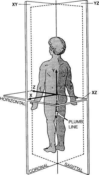
The anatomic position, with the erect body facing forward, the elbows and fingers extended at the sides of the body, with the palms and the feet facing forward, is the standard position of reference to describe any human motion (Figure 11-1). It should be apparent that not all motion or activities that we perform on a daily basis begin or end in this reference position. Additionally, we know that it is possible to perform motions in combination; for example, flexion and rotation occur together when bending forward to touch your right hand to your left foot. An accurate description of the characteristics of normal motion includes discussion on a central coordinate system and planar motion (Figure 11-2).
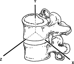
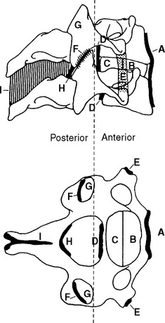
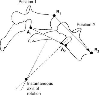
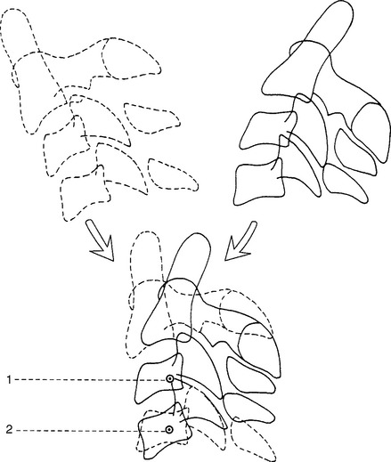
The fundamental unit of spinal movement referred to as the motion segment3 is a three-joint complex.4 This unit consists of an intervertebral disc surrounded by two adjacent vertebrae, the twoposterior joints, and the surrounding contiguous ligaments including capsules (Figure 11-3). The three-joint complex is the functional unit of spinal motion. Additionally, given the unique anatomy of the spinal motion segment, it is important to discuss coupled motion and an instantaneous axis of rotation (Figure 11-4) with respect to the potential for six degrees of freedom at this three-joint complex.
Central Coordinate System
The central coordinate system describes three-dimensional motion in the human body. In this system, motion and forces are defined as acting along any combination of three axes, X, Y, and Z. The X, Y, and Z axes are orientated at right angles to one another (see Figures 11-1 and 11-2) and define or locate the extent of two general types of movement—linear motion and angular or rotational motion.5,6 All movements that occur about an axis are considered rotational, whereas translational movements along an axis and through a plane are linear movements.5 Note then, that linear motion can occur along a straight or curved line (curvilinear). Curvilinear motion occurs when a rotational movement is accompanied by a translational movement.5
With three axes orientated 90 degrees to one another, any point in space can be exactly defined. Two of these axes may already look familiar. You may recall from geometry that the X and Y axes provide a two-dimensional description of a plane (or piece of graph paper) that has been divided into four quadrants. The center of these quadrants is located at the junction of the perpendicular lines and labeled the origin. The line running horizontally through the origin is the X axis (i.e., abscissa) and the line running vertically through the origin is the Y axis (i.e., ordinate). To describe motion in three dimensions, a third axis must be introduced. This is the Z axis, and it is perpendicular to both the X and Y axes. By convention, the origin of the three-dimensional coordinate system is placed at the body’s center of mass (approximately 2 cm anterior to the second sacral vertebra for the standing human). However, for many body motions, it is not always convenient to reference the center of mass. It is acceptable to reference any point from which movement can be defined. For example, when describing movement at a spinal motion segment, the origin of the three-axis coordinate system is placed at the center of the superiorvertebral body with the lower vertebra regarded as fixed. (See Figure 11-2.) Motion at the three-joint complex is then described by translation along or rotation around any of the three axes.
Some chiropractic authors suggest using the central coordinate system as a spinal listing method to describe fixation or subluxation of the spinal motion segment. For researchers, the coordinate system is useful for plotting vertebral displacement during a manipulative thrust; however, it can be confusing when used clinically to determine the direction for application of thrust in comparison to the common kinesiology terms of flexion, extension, lateral flexion, and rotation.7–10
Planar Motion
Planar motion is another way to characterize motions we are already familiar with, namely, flexion, extension, abduction, adduction, lateral flexion, and rotation (medial/lateral and right/left). Specifically, planar motion describes structural position and direction of functional movement. To move in a specific plane is to move a body segment parallel to that plane. (See Figure 11-1.) For example, flexion and extension occur in the sagittal plane; abduction, adduction, and lateral flexion occur in the coronal or frontal plane; and rotation occurs in the transverse or horizontal plane. What are these three planes of movement, and how do they relate to the central coordinate system? The three planes of human motion, horizontal or transverse, coronal or frontal, and sagittal, are illustrated in Figure 11-1. Each of these planes is defined according to the central coordinate system. Additionally, the body planes are derived from dimensions in space and are arranged perpendicular to one another. (See Figure 11-1.) The midsagittal and sagittal plane divides the body into right and left halves and is made up of the Y and Z axes, thereby forming the YZ plane. The coronal plane, also called the frontal plane, is at right angles to the sagittal plane and divides the body into anterior and posterior portions. It is defined by the X and Y axes, forming the XY plane. The transverse plane is a horizontal plane, dividing the body into upper and lower components and is defined by the X and Z axes forming the XZ plane.
Six Degrees of Freedom
Six degrees of freedom or directions of motion are available at the three-joint complex. These motions are described in relation to the central coordinate system. (See Figure 11-2.) The potential exists for a spinal joint to exhibit translational and rotational movements along and around each of the X, Y, and Z axes. Thus we characterize a motion segment as a viscoelastic, energy-absorbingentity possessing six degrees of motion.11–14 As we will see, rotation around these three axes is restricted by the plane that articular facet lies in and occurs in different amounts according to the region of the spine.15
Coupled Motion
Coupled motion is defined as vertebral movement around one axis (e.g., X axis), being consistently and automatically associated with movement around a second but different axis (e.g., Y axis).16 A sound understanding of coupled motion is important for understanding potential mechanisms of injury and in the appropriate application of rehabilitation methods. The concept of coupled motion is especially relevant during the chiropractic adjustment because vertebral motion can occur parallel to a plane of motion that is different from the plane in which force was applied. For example, during a rotational mobilization, Lee17 noted vertebral movement in all three anatomic planes. Additionally, coupled motion helps the chiropractic student better understand the rationale behind different preadjustment patient positioning techniques. Positioning the patient appropriately assists the doctor in isolating the spinal motion segment to be adjusted and improves the chance for success while minimizing patient discomfort and the possibility of injury.18
Coupled motion can also be thought of in terms of the six degrees of freedom available to the spinal motion segment. Coupling of more than one degree of freedom occurs when rotation or translation of the vertebra about one axis is consistently associated with rotation or translation of that same vertebra about another axis.15 Jofe et al.19 stated that coupling is primarily caused by the geometry of the regional facet articulations with the connecting ligaments and curvature of the spine having a secondary role. Coupled motions in the spine include flexion with axial rotation, lateral flexion with contralateral rotationand lateral flexion with ipsilateral rotation.16,20 It is important to note that when we discuss coupled motions, we are referencing the spinal motion segment such that gross movements occur independently of coupled motion.21 Imagine then, coupling occurring at the level of a single spinal motion segment. As we will see, spinal curvature and specific regional anatomical properties21–23 contribute to coupled motions such that coupling patterns will vary by spinal region. Altered and asymmetrical coupling of motions have been noted in persons with low back pain.21 Despite our attention to the concept of coupled motion, keep in mind that motion coupling differs across individuals and the clinical importance of normal and abnormal motion is still being debated.16,21 Instead, think of coupled motion as a guideline for patient positioning and force application rather than absolute truth for clinical application. As such, coupled motion will vary by spinal region, adding to the confusion and controversy regarding actual motion couplings.
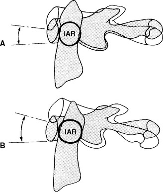
Instantaneous Axis of Rotation
Recall the description of motion as occurring around a particular axis. For example, the axis of rotation for flexion and extension is the X axis. This definition would hold in the human body if all of our joints were designed like the wheel of a bicycle. For the wheel, the axis of rotation is at the center (i.e., axle). A wheel is perfectly round (or at least very close to round); joints of the human body, however, are not symmetrically round. Because of this, small changes in the axis of rotation occur. The changing axis of rotation is referred to as the instantaneous axis of rotation (IAR). Interestingly, a vertebral body’s IAR may shift as different forces are applied.15
A rigid body’s motion can be described with reference to the IAR or helical axis of motion. At every instant of planar motion, there is a line through the body (or hypothetical extension of it) that does not move. This line is perpendicular to the motion plane and is defined as the IAR.15 (See Figure 11-4.) A helical axis of motion is defined as the unique axis in space that completely defines the three-dimensional motion of a rigid body from position 1 to position 2.24 It is analogous to the instantaneous axis of rotation for plane motion. According to the laws of mechanics, a rigid body may always be moved from position 1 to position 2 by a rotation about a certain axis and a translation along the same axis.24 This constitutes helical motion. The motion of a screw is an example of helical motion. A given instantaneous axis of rotation depends on the structure as well as the type of loading. The calculation for a particular vertebra differs as a result of various combinations of force and movement.15
Due to the incongruence between the curved surfaces of a joint, motion at the three-joint complex can occur through several axes at once. This concept is relevant to chiropractors with respect to defining a subluxation as having some component of aberrant motion. Changes to the IAR resulting in decreased aberrant motion have been reported following manipulation of the lumbar spine.7
Analysis of Motion
Before the advent of x-rays, range of motion was studied in cadavers.11,12,25,26 This posed difficulties because of postmortem changes that occur with cadaveric specimens and thus did not accurately reflect spinal mobility. Today, in vitro studies continue and attempt to simulate motion without consideration for the influence of muscle force (i.e., kinematics). Although in vivo procedures have been developed, they are too complex to perform clinically in a practical manner.
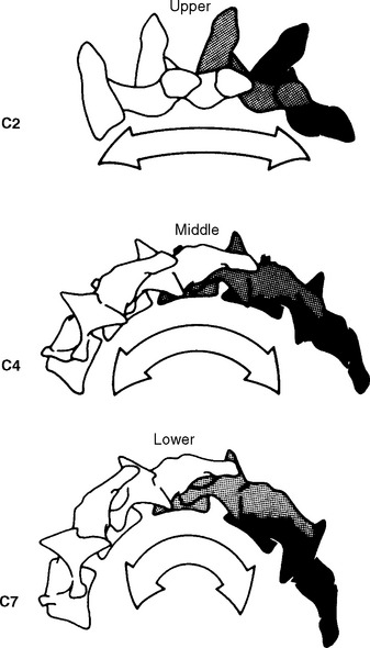
The analysis of normal and abnormal motion requires a system of measurement that can produce a reliable description of motion in a simple, accurate, and repeatable manner. Radiographic studies are often the initial imaging modality of choice. However, standard radiographic series provide static information only, capturing the structural status of the spine in one plane. “Functional” radiographs depict the instantaneous positions of a vertebra at the extremes of global range of motion. This imaging procedure is not truly “functional” and although individual segmental movement cannot be assessed, aberrant motion may be identified as restricted or increased, or as abnormal vertebral alignment at the end of a given range of motion. (See Chapter 6.) Various authors have used template analysis27 and “motor diagrams” from these radiographs to quantify motion (Figure 11-5).28–31 Dimnet et al.32,33 studied lateral cervical radiographs in full flexion, full extension, and three intermediate motions to detect angles and centers of movement for each vertebra.32 This same procedure was used earlier in the lumbar spine to observe lumbar sagittal plane motion.33 Coupled motions outside of the sagittal plane, however, have not be observed.
The dynamic evaluation of spinal motion has been advocated by many authors34 using stress radiographs. Stress radiographs consist of frontal radiographic views of the spine while the patient is placed in maximum right and left lateral bending, and lateral views of the spine while the patient is positioned in maximum lumbar flexion and extension.34 Stress radiographs, like functional radiographs, are not truly dynamic. Both still capture a single static moment in time. While the findings from these studies can be extrapolated to truly dynamic situations, their predictive validity should be used cautiously.
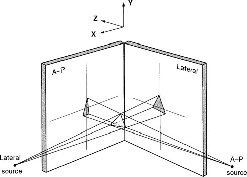
More sophisticated and costly imaging techniquesare now available, such as biplanar orthogonal radiography. Radiographs are taken simultaneouslythrough two x-ray tubes arranged at right angles to one another (Figure 11-6). Movement in all three planes can be detected and quantified.35–40
A year after Roentgen’s discovery of the x-ray in 1895, fluoroscopic screens were introduced, allowing for x-ray observation of dynamic events.41 In 1921, investigators began using cineradiography. This process documents fluoroscopic examinations by photographing a fluoroscopic screen with 16-mm or 35-mm motion picture film.41 The film can later be viewed at real-time, slow motion, or freeze-frame speeds. By the late 1950s, several researchers began to apply cineradiography to the skeletal system to evaluate joint motion.42–44 This technique allows for the study of dynamic motion with the contribution of the joints, disc, ligaments, and muscles. Cineradiography requires increased radiation dosages and poses difficulty to the investigator in quantifying the enormous amount of data.
The widespread availability of video recording systems in the 1970s and 1980s led to the inevitablereplacement of cineradiography by videofluoroscopy. Serial x-ray images were digitized from an image intensifier and directly interfaced to a computerized image processor. This digitized and displayed selected fluoroscopic images on a computer monitor. This spinal imaging modality is subject to observer variation in measuring angles and operator inconsistency.45 It has potential in evaluating asymmetrical or paradoxical motion and intersegmental motion with lower radiation exposures. Newer techniques such as dynamic computed tomography (CT) and magnetic resonance imaging (MRI) are being used to visualize three-dimensional moving images.41 In conclusion, the cost, dose, and yield must be evaluated before choosing a method of imaging to assess spinal kinematics.
Normal Intersegmental Motion by Spinal Region
The physiologic range of translation and rotation of a vertebra for each of the six degrees of freedom are explored in the cervical, thoracic, and lumbar spine. The reader should be aware that the literaturespans a wide range of techniques used to evaluate and describe ranges of motion. This will inherently cause conflicting data when quantifying and qualifying motion. In addition to this factor, biologic variation is always at play. Regardless of the spinal location, the quantity and quality of motion are determined by normal variation in sagittal curvature and segmental orientation,46,47 muscular control,48,49 facet orientation,50 and degenerative changes of the motion segments.51,52 For example, in the cervical spine, facets are orientated primarily in the coronal plane and provide resistance to translatory movements.53 Facets in the thoracic spine tend to be orientated between the coronal and sagittal planes while the lumbar facets are orientated more in the sagittal plane and provide greater resistance to rotation.53 The facets betweenL5 and the sacrum are an exception, being orientated mostly in the coronal plane.53
Cervical Spine
Atlantooccipital Joints
The atlantooccipital joint (i.e., C0 and C1) is formed by the articulation of the convex occipital condyle with the concave facet of the atlas. This is a symmetrical and mechanically linked joint.54 Movement at the atlantooccipital joint occurs predominately in the sagittal plane, producing flexion and extension as the condyles slide in the corresponding lateral masses of the atlas (Figure 11-7). Significant controversy exists as to the amount of flexion and extension available at this joint. Findings from radiographic studies have suggested as little as 13 degrees14,55 while cineradiographic studies have found sagittal plane motion of 35 degrees.43 Penning56 performed overlay studies on 20 healthy adults and found an average of 30 degrees sagittal motion, with a range of 25 to 45 degrees. In later studies, Panjabi et al.57 observed an average range of 24.5 degrees, approximately 21 degrees of extension and 3.5 degrees flexion. Differences in reported segmental motion may be related to head position. For example, Jones58 suggested two different patterns of total cervical flexion exist and differentially affect motion at the atlantooccipital joints. Cervical flexion initiated with the chin retracted produces greater motion at the C0-C1 segment compared to flexion starting with the head erect.
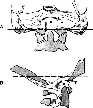
Most authors agree that pure rotation does not occur at the atlantooccipital joints.15,19,55,58 However, Kapandji54 believes that rotation between C0 and C1 (3 degrees) occurs secondary to rotation of the atlas about the odontoid and is accompanied by secondary minimal linear displacement to the same side of rotation and lateral flexion on the opposite side (Figure 11-8). Dvorak et al.,59 using computed tomography (CT), found the maximal rotational excursion of this joint to be 10.25 degrees while Penning and Wilmink60 reported a mean value of 1 degree rotation at this level using CT scans. Using stereophotogrammetry (measurements derived from three-dimensional photographs), Panjabi et al.57 reported as much as 7.2 degrees of ipsilateral axial rotation. (See Figure 11-8.)
Lateral flexion of the atlantooccipital articulation is limited not only by the osseous geometry but by the alar ligament attachment (Figure 11-9).24 Werne55 in his early studies on cadavers contended 11.9 degrees lateral bending with slightly less (7.8 degrees) on radiographs. Based on a review of the literature and their own analysis, White andPanjabi15 reported approximately 8 degrees of lateralflexion. Later, Panjabi et al.57 found lateral bending of 5.5 degrees using stereophotogrammetry.
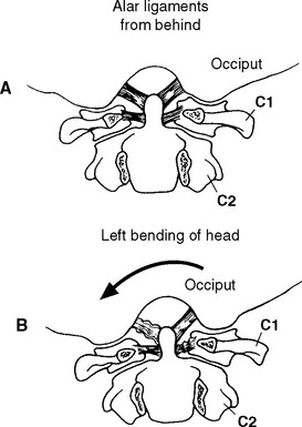
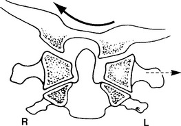
Due to the convex shape of the occipital condyles and concave shape of the atlas’s articular surfaces, movement in the coronal plane is coupledwith opposite movement in the transverse plane. Thus lateral flexion is coupled with rotation of the head to the opposite side.24,43,61 Additionally, with lateral flexion to the left, C1 translates to the left to adjust the position of the left lateral mass of C1, which otherwise would prevent lateral flexion to the left side (Figure 11-10). During left lateral flexion, the right alar ligament is pulled tight by this movement, pulling on the dens and rotating the C2 spinous process to the right. Penning56 contends that lateral bending of the atlantooccipital segment is always combined with lateral bendingand slight rotation of the C1-C2 joint. Jirout,61 however, suggests that rotation of the atlas from the side of inclination cannot be looked on as normal and constant because it does not occur.
The instantaneous axis of rotation for flexion/extension is located in a sagittal axis 2 to 3 cm above the apex of the dens.24 For lateral bending, the axis appears to be located in the midline, slightly more distant from the tip of the dens.62 Because there is very little or no axial rotation at the occipitoatlantal articulation, the instantaneous axis of rotation for this plane is not considered (Figure 11-11).
Atlantoaxial Joints
The mechanically linked four-joint complex between C1 and C2 lacks the disc of the typical vertebral motion segment.63 Thus the pattern of motion is primarily controlled by the geometry of the osseous and ligamentous articulations. There are two paired atlantoaxial joints, one central atlantoodontoid joint, and one joint between the transverse ligament and the posterior aspect of the odontoid process.
The predominate motion at the atlantoaxial joints is rotation of the atlas around the Y axis of the odontoid process. Werne55 reported rotational movement of 47 degrees, accounting for 40% to 50% of the total axial rotation available in the cervical spine and making the atlantoaxial joints the most mobile segment of the cervical spine. Similar values for rotation have been reported by Panjabi and White.15 Compared to the atlantooccipital joints, there is less discrepancy in the degree of rotation occurring at the atlantoaxial joints. Penning and Wilmink60 report 40.5 degrees of rotational motion to either side, with a range of 29 to 46 degrees. Work by Dvorak et al.59 as well as Panjabi et al.57 support findings that a range of rotational motion likely exists at the atlantoaxial joints; the researchers found an average of 32.2 degrees and 38.9 degrees, respectively.
The coupled motion during rotation is a “screwlike” mechanism, allowing the atlas to drop 2 to 3 mm because of the biconvexity of the joint surfaces (Figure 11-12). With rotation, there is also an associated coupling of ipsilateral lateral bending to a small degree.56 This vertical approximation was confirmed by Hohl64 using cineradiographs. Werne55 concluded that vertical displacementor amount that the atlas drops depends on the extent to which the longitudinal axis of the dens correlates with the imaginary longitudinal axis of the body. The more parallel the two are, the more distinctive the vertical displacement.55 Jirout65 usedx-ray analysis to formulate conclusions regarding rotation and linear displacement. In his model, rotation had two phases. The initial phase involveda symmetrical rotation of C2 around the longitudinalaxis of the cervical spine (attributable to the facet joints), followed by an asymmetrical phase of further rotation (influenced by the addition of muscle traction) with pronounced lateral translation of the axis against the atlas.
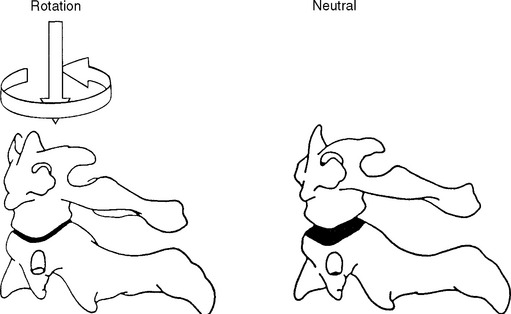
Figure 11-12 Coupled motion: vertical translation of C1 with axial translation of C1 on C2.
(From Bergmann TF, Peterson DH, Lawrence DJ. Chiropractic technique. New York: Churchill Livingstone; 1993. p. 222.)
During flexion and extension, the anterior arch of C1 slides superiorly and inferiorly on the odontoid process as the inferior facets of C1 roll and slide on the superior facets of C2. In flexion, the posterior joint capsule and posterior arches separate and the articular surface of the atlas glides forward. In extension, the posterior joint capsule and posterior arches approximate and the articularsurface of the atlas glides posteriorly.66 Panjabi et al.57 report 11.5 degrees flexion and 10.9 degreesextension at the atlantoaxial joint. Similar measurements have been reported by Werne55 and Hohl,64 who demonstrated 10 degrees of flexion and extension. Penning56 used movement diagrams from functional radiographs during flexion and extension and found an average 30 degrees of motion with a range of 25 to 45 degrees. Although it is generally accepted that there is little measurable lateral flexion at the atlantoaxial joint,19 Penning56 reports a mean value of 10 degrees to each side while Panjabi et al.57 report 6.7 degrees of lateral flexion to one side at the atlantoaxial segment.
Flexion and extension movements of the atlantoaxial joint are coupled with small translational movements from 2 to 3 mm in the adult and up to 4.5 mm in the child.24 The atlantodental interspace also diminishes during flexion, creating a V-shaped appearance.43 Although there is still controversy as to whether lateral (X axis) translation of the atlantoaxial joint occurs, most of the literature suggests that a displacement of 0 to 4 mm is normal.19
The instantaneous axis of rotation for the atlantoaxial joint has been located through cineradiographic studies to the middle third of the dens during flexion and extension (Figure 11-13).55 For axial rotation, the axis may be assumed to lie in the center portion of the axis (Figure 11-14).19 Because lateral flexion at this joint is small or nonexistent, the location of an axis for this motionmay be deemed irrelevant.62

Lower Cervical Spine
The lower cervical spine from the second to the seventh vertebra possesses six degrees of motion: flexion, extension, rotation (right and left), and lateral flexion (right and left). Range of motion for the typical vertebrae of the cervical spine is determined by osseous geometry and the stiffness of the disc.14 Additional variations in motion can occur due to age because younger individuals may possess general ligamentous laxity, demonstrating disproportionately greater motion at C2-C3 compared to adults who tend to show the greatest amount of flexion at C4-C5 or C5-C6.67
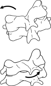
Cervical spine flexion and extension predominately occur in the lower cervical spine and are coupled with translation and rotation (Table 11-2).Figure 11-15 depicts movement of the spinal motion segment with the superior vertebrae tilting and gliding on the articular surfaces of the lower facet joints, producing the total motion required by the head and neck. The coupled translation that occurs with flexion and extension has been measured at approximately 2 mm per segment.19,68 In the sagittal plane, translation along the Z axis occurs in decreasing magnitude approaching the C7 vertebra,15 producing a “stair-step” effect. In addition, for every degree of sagittal plane rotation, more translation occurs in the upper cervical segments than in the lower cervical segments.66 This translation has been attributed to the inclination of the facet joints.43 Conversely, the caudal segments tend to have a larger amount of tilt.28
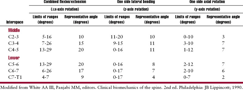
Lateral flexion averages approximately 10 degrees (segmentally) to each side in the mid cervicalsegments, with decreasing flexibility in the caudal segments.66 (See Table 11-2.) Lateral flexion in the lower cervical spine is coupled with rotation such that ipsilateral lateral bending is coupled with rotation of the spinous process to the contralateral side (or convexity of the curve) (Figure 11-16). The degree of coupled motion decreases in a caudal direction.66 For example, at the second cervical vertebra, there are 2 degrees of coupled axial rotation for every 3 degrees of lateral bending, a ratio of2:3.19 At the seventh vertebra, there is 1 degree of coupledaxial rotation for every 7.5 degrees of lateral bending, a ratio of 1:7.5. Jofe19 theorizes that the gradual change in coupling ratio may be related to the change in inclination of the facet joints. The greatest obliquity of the facet joints is at C2-C3 (40 to 45 degrees), progressively decreasing to 10 degrees atC7-T1.54 Kapandji54 also believes that during lateralflexion some degree of extension occurs as a result of anatomic structure.

Stay updated, free articles. Join our Telegram channel

Full access? Get Clinical Tree


