Fig. 5.1
The active resisted hamstring contraction stress X-ray. The patient is performing an active maximal hamstring contraction against resistance in the lateral position. The X-ray is done during the maximal contraction. (From Carson and Johnson 2013 [36]. Reprinted with permission)
Axial View
A modified axial patellofemoral radiograph has been described as a quick and easy form of stress view to assess the integrity of the posterior structures of the knee. The patient is positioned supine with the knees flexed to 70°, feet flat on the table in moderate plantar flexion, and the tibia in neutral rotation. The X-ray beam is then directed from distal to proximal and parallel to the longitudinal axis of the patella, at an upward angle of 10° to the X-ray table. Early results of the technique were promising [3]. However, more recent multi-technique comparisons have shown it to be a less reliable technique compared to the alternative stress views [2, 4].
Posterior Sag/Gravity View
The patient is positioned supine on the X-ray table, and both the hip and knee are flexed to 90°. The tibia is held in place in neutral rotation. A true lateral radiograph of the knee is then obtained. The method is quick and easy, but has not compared favorably to other stress views [4].
Kneeling Stress View
The stress view yielding the best and most reliable results thus far is the kneeling stress view. The patient kneels on a bench or similar structure with the knee over the edge of the bench (i.e., the femoral condyles are past the bench, while the tibial tubercle is supported by it). The knee is maintained at 90° of flexion. A true lateral radiograph of the knee is then taken. Measurement of displacement is then performed using the posterior cortex of the tibia and posterior cortex of the distal femur. The kneeling stress view was found to have very high inter- and intra-observer reliability [5], and to be reliable evaluation of posterior laxity [6].
Of note, however, a recent study comparing Telos stress views to kneeling stress views showed significantly different displacement measurements—both pre- and post-reconstructive surgery [7]. This has been hypothesized to likely be due to the difference in force placed on the anterior tibia with the two techniques. Further study will therefore be required to better define normative displacement measurements for the kneeling exam. Moreover, a larger comparative study to other available methods is necessary to determine the value of the kneeling stress view in quantitating the posterior instability.
Valgus Stress
A valgus force applied to the knee will put stress on the medial collateral ligament (MCL) opening the medial compartment and allow for grading of MCL injury. The patient is positioned supine on a radiolucent table, and their knees bound together. The examiner is then able to apply valgus stress to both knees by attempting to separate the patient’s feet from the foot of the bed. The knees should be maintained in approximately 10–15° of flexion, and the feet slightly externally rotated while performing the stress. An anteroposterior (AP) radiograph is then taken of the knee at the endpoint of displacement. Displacement is measured from the medial plateau to the femoral condylar line [8] and the uninjured knee is used as the control (normal) value (Fig. 5.2).
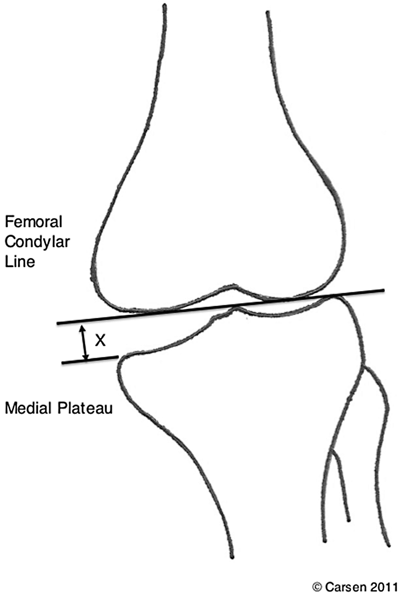

Fig. 5.2
The opening of the medial joint space is measured in millimeters. (From Carson and Johnson 2013 [36]. Reprinted with permission)
Varus Stress
Varus stress radiography has been found to correlate well with MRI findings and be helpful in determining which lateral/posterolateral corner injuries should be surgically repaired or reconstructed [9]. Gawthmey et al. found that a lateral joint opening averaging 18.6 mm (range 10.0–36.5 mm) was associated with a complete posterolateral corner (PLC) disruption on MRI while an opening of 12.8 mm (range 7.5–17.0 mm) was reflective of a partial tear. Opening in operative cases that underwent PLC stabilization was, on average, 16.5 mm (11.0–36.5 mm) versus 11.0 mm (range 7.5–13.5 mm) in those that were treated nonoperatively [9].
Advantages
Cost-effective
Some protocols have very good reliability and effectiveness
Disadvantages
Training for clinicians and radiation technologists
Standardization of protocols is necessary to obtain comparable data
Instrumented Stress Radiography
Telos Stress Radiography
The Telos Stress Device (Austin and Associates Inc. Fallson MD) is a commercially available system that allows for the application of consistent and reproducible stress forces to the index knee joint, while radiographs are obtained (Fig. 5.3). Measurement of displacement on the radiograph can then be performed. Depending on the patient’s position and device’s orientation, it can be used to stress the tibiofemoral joint anteriorly, posteriorly, medially, or laterally, thereby assessing the ACL, PCL/PLC/posteromedial corner (PMC), MCL, and lateral collateral ligament (LCL), respectively.
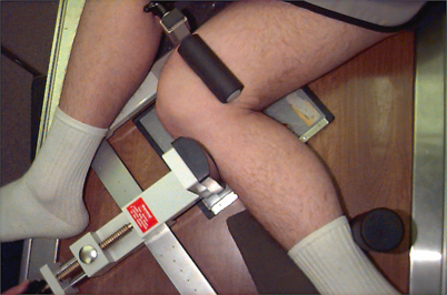

Fig. 5.3
The stress X-ray examination of the PCL-deficient knee with the Telos device. (From Carson and Johnson 2013 [36]. Reprinted with permission). PCL posterior cruciate ligament
Posterior Stress
To perform a posterior stress X-ray utilizing the Telos device, the patient is positioned in the lateral decubitus position, index knee dependent on the radiolucent table. The knee is positioned at 90° of flexion inside the Telos device (Fig. 5.3). The knee must be in neutral rotation. A 15-kPa force is exerted on the anterior tibial tubercle, and a lateral X-ray is performed. The knee must be positioned in a true lateral position, which should be confirmed by superimposition of the lateral and medial femoral condyles on the radiograph.
Measurement of displacement is performed by using the Telos template, aligning the inferior horizontal line parallel to and overlying the tibial plateau. The perpendicular “zero” line is then lined up with the posterior border of the tibial plateau. The measurement of posterior displacement is then made in millimeters between the posterior border of the tibial plateau and the posterior border of femoral condyles.
The degree of posterior displacement is measured with a template on the lateral stress X-ray (Fig. 5.4). In this example, the posterior displacement is 17 mm.
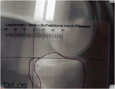

Fig. 5.4
The Telos stress X-ray with the measuring template. (From Carson and Johnson 2013 [36]. Reprinted with permission)
The difficulties with this method are:
It is essential to have a true lateral X-ray with the femoral condyles overlapping as shown in Fig. 5.4.
The template must be accurately positioned to ensure reproducible measurements.
One of the most significant challenges with the Telos system is ensuring standardized measurement. Following a standardized protocol when performing the radiographs produces reliable and reproducible measurements [10].
A recently published study conducted over 12 years using the Telos device for the evaluation of knee instability in more than 1000 patients found it to be reliable and effective at diagnosing posterior laxity [11]. They found that a measurement of greater than 8 mm of posterior displacement was diagnostic for complete PCL rupture, while a measurement of greater than 12 mm was indicative of injury to secondary supporting structures as well (PLC and/or PMC).
Anterior Stress
The Telos system has not been as helpful in assessing the magnitude of anterior laxity of the knee. Rijk et al. found that an anterior displacement of more than 7 mm was abnormal, with a false-negative rate of 12 % [12]. The patient and device positioning for anterior stress testing is essentially identical to the posterior stress exam, with the position reversed.
Recently, Dejour et al. demonstrated that the Telos device in conjunction with clinical examination (pivot shift test) was helpful in differentiating partial from complete ACL ruptures [13].
Advantages
Accurate measurement of the posterior displacement with a template.
Disadvantages
The use of X-rays/radiation.
The radiological technician must be trained in the correct use of the device.
Expense of the Telos device.
Knee Ligament Arthrometers
KT-1000/2000
The KT-1000 and KT-2000 (the KT-2000 is essentially the same as the KT-1000 but with an added graphic plotting interface) are arthrometers that measure anterior–posterior tibiofemoral translation (i.e., translation in the sagittal plane only).
Anterior
The KT-1000 knee ligament arthrometer (MEDMetric Corp., San Diego, CA), developed by Dale Daniel and Larry Malcolm [14], has become the standard for the measurement of ACL laxity. Starting from its introduction in the early 1980s, it has continued to be found to be accurate and reliable in the measurement of anterior translation of the tibia on the femur [15]. It has proven to have strong reliability, with good inter- and intra-rater performance [16]. It has recently performed equally compared with intra-operative computer-assisted surgery/navigation [17]. The device is used with the patient supine and a support platform placed under both thighs to maintain approximately 25–35° flexion of both knees. The feet are supported on the lateral aspects by a second platform to ensure the same relative rotation of both lower legs. This position is ideal for the performance of an instrumented Lachman test on both knees. The arthrometer is placed secured with Velcro straps on the knee and lower leg such that the force pad is located over the tibial tubercle, and the patellar pad is resting on the anterior surface of the patella. The patella pad is gently stabilized while the force handle is pushed and pulled to achieve tibiofemoral translation readings (Fig. 5.5). The maximum manual test has been found to have the highest diagnostic value for the determination of ACL laxity and is performed by using a hand behind the calf to produce a maximal anterior translation force [18].
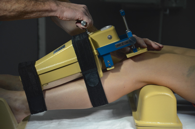

Fig. 5.5
This photo shows the KT-1000 device used to measure the anterior tibial displacement
The best results with the KT-1000 are obtained when comparing side-to-side difference within the same patient, and when the same examiner performs the repetitive exams. Though the KT-1000 arthrometer is simple to use, there is still an association of increased accuracy and reproducibility with the experienced user.
Posterior
The KT-1000 has not, however, achieved the same level of acceptance for the quantitative measurement of posterior instability. Daniel [19] described the method of measuring posterior laxity by first determining the quadriceps neutral point.
The principle of the measurement as described by Daniel is to determine the four levels of anterior-to-posterior motion:
Anterior
Quadriceps neutral
Posterior sag
Posterior displacement
Initially, the patient contracts the quadriceps muscle sufficiently to bring the tibial forward to the “quadriceps neutral” position.
The posterior motion from this point is then recorded as the posterior sag, and then the posterior displacement with 20 pounds of posterior force is measured and noted as the posterior displacement (Fig. 5.6). The total amount of posterior motion is determined when these two later values are added.
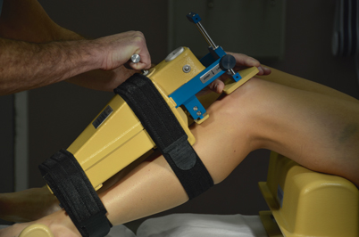

Fig. 5.6
This photo demonstrates the KT-1000 device positioned to measure posterior tibial translation
In our experience, it is often difficult to get the patient to contract their quadriceps sufficiently to bring the tibia fully forward to the neutral position. This amount of forward displacement is often underestimated. Johnson presented a study to the PCL study group in 1995, comparing the KT value against the stress X-ray [20]. The results were:
When the millimeters of displacement of the KT is expressed as a percentage of the Telos:
> 10 mm of posterior displacement—the KT is 65 % of the Telos
Stay updated, free articles. Join our Telegram channel

Full access? Get Clinical Tree


