Fig. 11.1
Intraoperative physical exam finding of the PCL-deficient knee; a posterior sag of the right tibia in 90° of flexion
Radiography
The initial diagnostic imaging study should be plain radiographs (anteroposterior and lateral) of the knee. These initial radiographs are helpful in that they can rule out a fracture or an unreduced knee in the acute setting. Plain radiographs can be used to assess the medial or patellofemoral compartments for arthrosis in patients who present with a suspected chronic PCL deficiency. Long-leg standing films should be obtained if any fixed or dynamic instability is suspected or if there is evidence of extra-articular deformity. Posterior tibial subluxation may be evaluated on standard lateral radiographs; however, if there is any doubt bilateral stress (weighted) radiographs should be performed (Fig. 11.2).
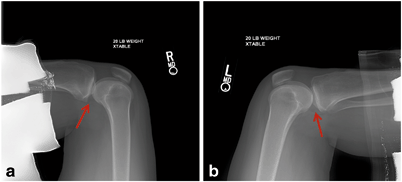
Fig. 11.2
Stress radiographs of the bilateral knees. The normal anatomic position of the tibia in relation to the femur (arrow) in a ligamentously intact knee (a). Posterior tibial subluxation in relation to the femur (arrow) is present in a PCL-deficient knee (b)
Other Imaging Modalities
Although not regularly utilized in our current diagnostic algorithm, the extent of degenerative changes in the chronically PCL- deficient knee can be assessed with a bone scan. More commonly, a magnetic resonance imaging (MRI ) study is an essential part of the work up of a PCL injury . The MRI serves to confirm the suspected PCL rupture but more importantly provides an assessment of associated ligamentous injuries such as those to the PLC that will affect the preoperative plan, the surgical technique, and ultimately the clinical outcome (Fig. 11.3).
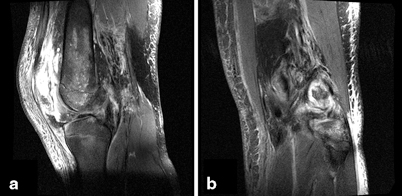
Fig. 11.3
Magnetic resonance imaging of a patient who sustained an acute complete tear of the PCL off the femur (a) and a patient with a concomitant PLC injury in the presence of an acute PCL tear (b).
Indications and Contraindications
Patients who sustain acute isolated grade I or II PCL injuries should be treated with nonoperative, protected weight bearing, and progressive rehabilitation. The grade I or II injuries that do not respond well to nonoperative measures and go on to have persistent or recurrent instability may be treated surgically. Grade III isolated PCL tears should be treated with surgical reconstruction, although not all authors agree on the existence of an isolated grade III PCL injury [10–12]. The majority of acute PCL ruptures occur as part of a larger constellation of knee injury, either a multiligamentous knee injury or a knee dislocation. In either case, surgical intervention is advocated for in the majority of patients, especially those patients who are young and active. The timing of intervention remains controversial; however, the literature supports either early or late reconstruction depending on the severity of injury (isolated PCL vs. multiligamentous injury), the surgeon’s preference, and the patient’s activity level [6, 12–18]. In the presence of an acute bony avulsion, early reconstruction is generally advocated.
There are a number of instances in which an acute PCL-R is contraindicated. In the setting of a traumatic open knee injury or in the presence of a neurovascular injury requiring repair or reconstruction, the PCL-R should be deferred into the late period to allow for resolution of the open injury or nervous insult. Relative contraindications to PCL-R include the presence of a chronic, fixed posteriorly subluxated deformity of the tibia and the PCL-deficient knee in which significant arthrosis is present. In both of the aforementioned scenarios, for the best clinical outcome, the senior author recommends a biplane osteotomy rather than a soft tissue reconstruction.
Surgical Technique
Overview
Once the decision has been made to proceed to the operating room for PCL -R , there are a number of surgical variables to consider; including graft material, number of graft bundles, and surgical technique (transtibial vs. open inlay vs. arthroscopic inlay). First to address the issue of number of graft bundles, recent biomechanical studies and a systematic review of the literature concluded that while there are no clinical studies to suggest an advantage of double-bundle grafts, there are distinct biomechanical advantages to the double-bundle PCL-R [19–21]. Thus, the senior author (JKS) has transitioned to the use of double-bundle grafts in primary PCL-R and when possible in revision PCL-R. The evolution of PCL-R surgical technique has been such that the all-arthroscopic tibial inlay technique has combined the advantages of both the transtibial and open inlay techniques while obviating the disadvantages of each technique [22–24]. For these reasons, the double-bundle arthroscopic inlay technique is our preferred technique for PCL-R and will be presented here.
Anesthesia and Positioning
Preoperative femoral and sciatic nerve catheters may be placed in the preoperative holding area for postoperative pain management. The catheters should not be dosed until a postoperative neurovascular assessment is complete in the recovery room. Following catheter placement, the patient is then transported to the operating room and placed supine on a radiolucent table. The radiolucent table is paramount as fluoroscopic confirmation of tunnel position and orientation will be necessary throughout the case. The patient should undergo general anesthesia and endotracheal intubation, but it is important to communicate with the anesthesia team that no long-acting paralytics should be given to ensure all neurologic stimulation induces a response. Once the patient is anesthetized and intubated, a comprehensive exam under anesthesia is performed to assess the integrity of all ligamentous and soft tissue structures of the knee. The results of the examination under anesthesia often aid in dictating the surgical plan. Once the exam is complete, the patient’s nonoperative extremity bony prominences are well padded and a sandbag bump is taped to the bed. The bulk of the surgical work is performed between 45° and 90 ° of flexion and to facilitate these flexion angles, the sandbag is taped to the ipsilateral side of the table roughly at the level of the contralateral heel cord (Fig. 11.4). Additionally, doing the majority of the surgical procedure in flexion is a safety measure as flexion ensures the contents of the popliteal fossa fall away from the posterior tibia to allow for safe arthroscopic dissection of the tibial footprint. Although rarely inflated, a well-padded tourniquet is applied to the ipsilateral proximal thigh. The main advantage to working without the tourniquet is the early detection of a vascular injury if one was to occur. Lastly, when positioning, a flip-down lateral post is placed at the level of the tourniquet and set in a high position to act as a buttress for levering of the leg if a valgus force is necessary for medial compartment work.
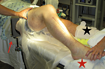
Fig. 11.4
Surgical positioning for the arthroscopic inlay procedure. A sandbag or bump is secured to the radiolucent table to allow the operative knee to be ranged in the flexion arc of 45–90 ° (red star). A lateral post is attached to the table at the level of the thigh tourniquet to act as a fulcrum when placing a valgus force on the knee (red arrow). The contralateral leg is well padded and a sequential compression device is placed for deep venous thrombus prophylaxis (black star)
Portal Placement
Slight adjustments are made to the standard arthroscopic portal locations for the all-arthroscopic tibial inlay double-bundle PCL -R. A standard anterolateral (AL) portal is made, but the anteromedial (AM) portal is altered. The AM portal must be established in closer proximity to the patellar tendon for increased access to the posteromedial joint space. Later in the procedure, at the time of graft passage, the AM portal is extended into a 2-cm parapatellar arthrotomy to facilitate graft passage. The location of the posteromedial working portal is also crucial to prevent surgical struggle and should thus be established under direct visualization. An 18-gauge spinal needle is used to access the posteromedial aspect of the joint on a line between the posteromedial edge of the tibia and the femoral condyle. The posteromedial working portal is first utilized to clear the tibial footprint of the PCL and as such the ideal portal placement is approximately 1 cm cranial to the posteromedial joint line.
Once the three initial portals are created, a thorough diagnostic arthroscopic exam is conducted. The exam should include an evaluation of the integrity of all ligaments, menisci, and chondral surfaces. Injuries to the posteromedial and posterolateral corners are evaluated with increased opening of the medial and lateral compartments respectively under conditions of valgus and varus stress. In either case, a missed corner injury will place undue stress on the PCL -R and lead to increased risk of clinical failure.
Tibial Socket
The tibial socket is created prior to the femoral tunnels. First, a PCL guide pin (Arthrex Inc., Naples, FL, USA) is drilled from the anterior tibial surface into and through the tibial PCL footprint . This step is done with the assistance of fluoroscopy and under direct arthroscopic visualization. The target for insertion of the guide pin is within the footprint and 7 mm distal to the proximal pole of the tibial footprint. The corresponding 3.5-mm cannulated drill is used to over-drill the guide pin and once again the position is confirmed arthroscopically (Fig. 11.5a). Care is taken to avoid altering the tunnel trajectory by changing hand position while drilling and, more importantly, care is taken to avoid plunging into the posterior structures of the knee. Two safety mechanisms are employed to avoid plunging: the first is that the reaming position can be confirmed fluoroscopically or with direct arthroscopic visualization. The second is that the newest iteration of the drill guide has a built-in 13-mm footplate that protects against plunging (Arthrex Inc.). If another drilling system is employed, a straight curette may be placed on top of the guide pin, entering the joint via the AM portal. Once the tunnel is reamed, the tibial socket is ready to be created with the FlipCutter (Arthrex Inc.). The drill and guide pin are removed and replaced by the FlipCutter (Arthrex Inc.), which is advanced through the tibial tunnel until it is visualized intra-articularly with the arthroscope (Fig. 11.5b). Once the working end of the FlipCutter is within the joint, the blade is engaged by “flipping” it into a perpendicular position. The blade is activated and a 13-mm diameter tibial socket to a depth of 10–12 mm is then drilled in a retrograde fashion (Fig. 11.6). The FlipCutter blade is then advanced into the joint and “flipped” back into the upright positioned to enable the device to be withdrawn.
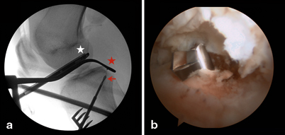
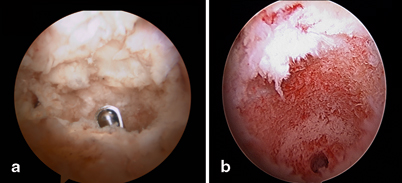
Fig. 11.5
Creation of the tibial socket. Fluoroscopic image demonstrating the PCL guide system (red star) and the cannulated drilling of the tibial socket (red arrow) (a). This step is done under fluoroscopic and direct arthroscopic visualization (white star). Arthroscopic view confirming successful insertion and position of the FlipCutter at the tibial footprint of the PCL (b)
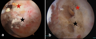
Fig. 11.6
Arthroscopic images of the completed tibial socket reamed by the FlipCutter. Anterior to posterior arthroscopic image with shaver-clearing debride from tibial socket (a). Arthroscopic view of the tibial socket; diameter 13 mm, depth 10–12 mm (b)
Graft Preparation
In cases of isolated PCL -R autograft, tendon–bone constructs may be considered; however, the majority of operative PCL injuries include additional soft tissue/ligamentous injuries requiring reconstruction, thus allograft is preferred. The current graft of choice is the Achilles tendon allograft with calcaneal bone block. With this technique, there is no clinical outcome study we are aware of to suggest a superiority of allograft or autograft; however, the Achilles tendon–bone allograft is a natural graft choice as the anatomic raphe between the superficial and deep fibers facilitates the creation of two bundles (Fig. 11.7a). Sharp dissection is used to develop the interval between deep and superficial Achilles fibers, in line with the longitudinal fibers of the graft to a distance of approximately 1 cm proximal of the calcaneal bone block. The newly created graft bundles are oriented in the anterior-to-posterior orientation with the larger bundle (8–11 mm) for the anterolateral bundle (ALB) and the smaller bundle (6–9 mm) for the posteromedial bundle (PMB). Each bundle of the bifid graft is reinforced with a No. 2 braided, nonabsorbable whipstitch (Fig. 11.7b).
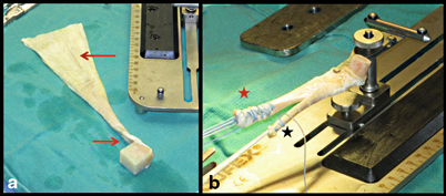
Fig. 11.7
Preparation of the soft tissue segment of the tendon–bone graft. The natural raphe of the Achilles tendon allograft is appreciated (red arrows) before sharply dissecting the graft into two limbs (a). Each limb is whipstitched and tubularized with a No. 2 braided, nonabsorbable suture; ALB (red star) and PMB (black star) (b)
Attention is then turned to trimming and shaping the calcaneal bone plug for a press fit into the tibial socket. The stability of the all-arthroscopic tibial inlay PCL -R technique relies heavily on the press-fit design of the graft [25]. The proper press fit for a 13-mm socket is a cylindrical 12-mm bone plug, which can be either created with the aid of a coring reamer or hand whittled with a rongeur. The coring reamer is the most expedient and accurate method; however, there is a learning curve associated with this technique. Once the outer diameter of the bone plug is established, a central tunnel is created within the bone plug and over-reamed to a diameter of 3.5 mm with a cannulated drill system. The 1 cm of tendon left in continuity is then whipstitched with a No. 2 braided nonabsorbable suture and the free ends of this stitch are passed through the center tunnel of the bone plug from the cortical to cancellous side of the bone plug (Fig. 11.8). The free limbs passing through the bone block aid in guiding the bone plug into position. Once the bone block is seated and the graft is tensioned, the free limbs are tied over a post or button to augment tibial fixation. Recently, we have transitioned to the use of cortical button fixation which we have tested biomechanically in the laboratory and found to be equivalent in strength to post fixation. In addition to equivalent strength and stiffness, the cortical button has ease of use and improved visualization to seat the bone plug fluoroscopically.
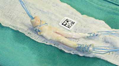
Fig. 11.8
Preparation of the bone segment of the tendon–bone graft. After sculpting the cubed bone block into a cylinder, the central calcaneal aperture is created with the use of a 3.5-mm drill system. The graft is finalized by passing a No. 2 braided, nonabsorbable suture through the remaining 1 cm of intact tendon at the bone plug end of the graft. The free limbs are then shuttled through the bone plug to aid in guiding the bone plug into the tibial socket and ultimately assisting with fixation
Femoral Tunnel
The femoral tunnels may be created inside out or outside in; however, for accuracy of placement we prefer the outside-in technique. A skin incision is made anteromedially overlying the vastus medialis obliquus (VMO) at the level of the medial epicondyle extending in line and anterior to the intermuscular septum. Once the fascia is incised, the VMO is elevated with a Cobb and retracted with a deaver or deaver-like retractor over the anterior femur. The periosteum is then exposed to clearly identify the starting position for the tunnels and ensure accurate tunnel position. The ideal tunnel for the ALB places the anterior edge of the ALB 1–2 mm off the articular margin of the medial femoral condyle at the 11:30 (left) or 12:30 (right) clock position. To create this tunnel, the guide pin is placed approximately 5 mm posterior to the articular margin (Fig. 11.9). For the PMB, the guide pin is placed 7 mm off the articular margin at the 9:00 (left) or 3:00 (right) position. The edge of the drilled tunnel should lie approximately 3 mm off the articular margin (Fig. 11.9). The technical challenge in femoral tunnel drilling is avoidance of tunnel convergence which will ultimately result in bone bridge collapse and loss of the potential benefits of a double-bundle reconstruction.
 Instrumented Measurement of the Multiple-Ligament-Injured Knee: Arthrometry, Stress Radiography, Rotationometry, and Computer Navigation
Anatomy and Biomechanics of the Posterior Cruciate Ligament and Their Surgical Implications
The All-Inside Technique: Surgical Technique and Outcomes
Arthroscopic Primary Repair of Posterior Cruciate Ligament Injuries
Open Tibial Inlay Graft for Posterior Cruciate Ligament Reconstruction
Combined PCL, ACL, Posteromedial, and Posterolateral Reconstruction
Instrumented Measurement of the Multiple-Ligament-Injured Knee: Arthrometry, Stress Radiography, Rotationometry, and Computer Navigation
Anatomy and Biomechanics of the Posterior Cruciate Ligament and Their Surgical Implications
The All-Inside Technique: Surgical Technique and Outcomes
Arthroscopic Primary Repair of Posterior Cruciate Ligament Injuries
Open Tibial Inlay Graft for Posterior Cruciate Ligament Reconstruction
Combined PCL, ACL, Posteromedial, and Posterolateral Reconstruction


Related posts:
Instrumented Measurement of the Multiple-Ligament-Injured Knee: Arthrometry, Stress Radiography, Rotationometry, and Computer Navigation
Anatomy and Biomechanics of the Posterior Cruciate Ligament and Their Surgical Implications
The All-Inside Technique: Surgical Technique and Outcomes
Arthroscopic Primary Repair of Posterior Cruciate Ligament Injuries
Open Tibial Inlay Graft for Posterior Cruciate Ligament Reconstruction
Combined PCL, ACL, Posteromedial, and Posterolateral Reconstruction
Stay updated, free articles. Join our Telegram channel
Full access? Get Clinical Tree
