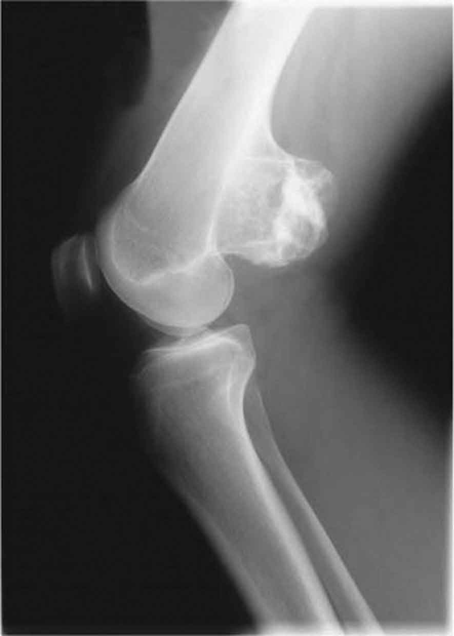
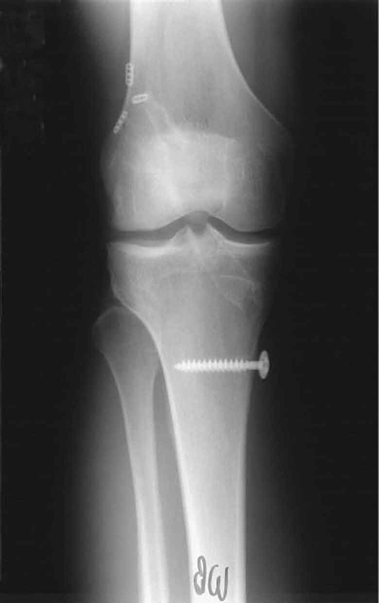
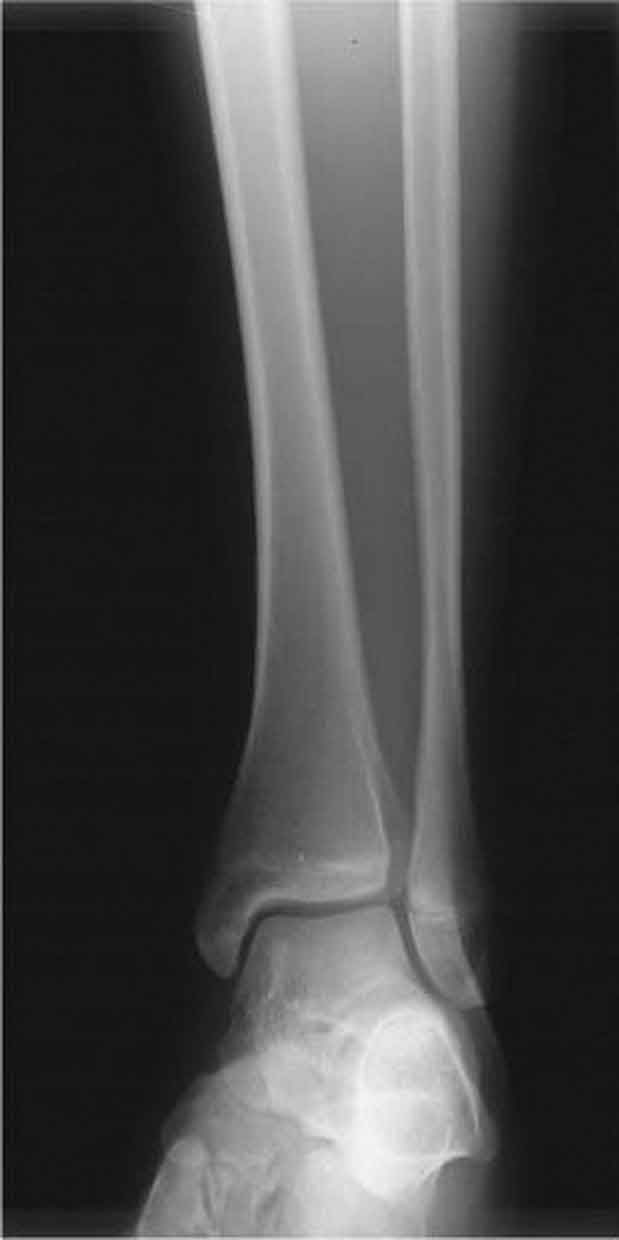
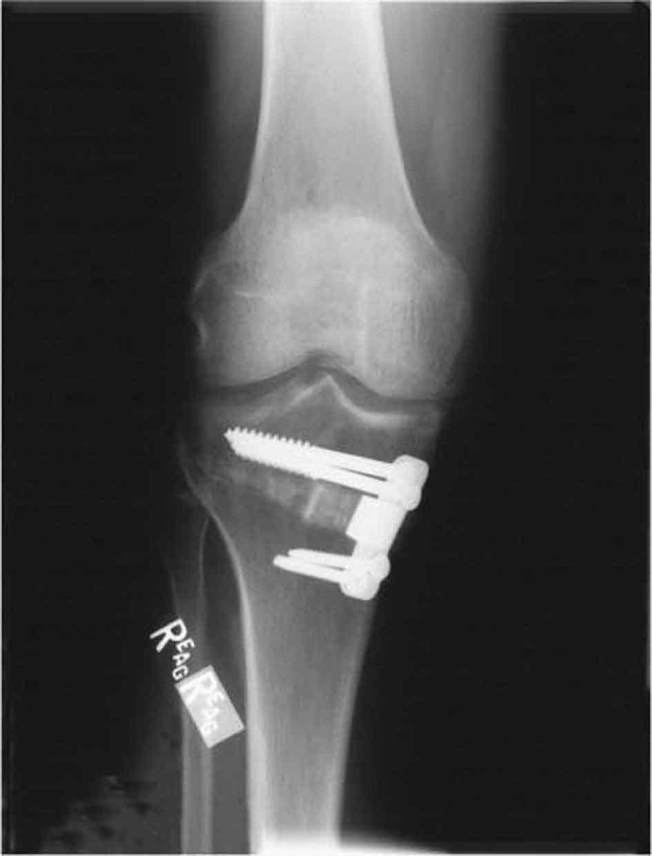
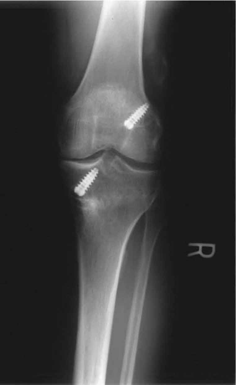
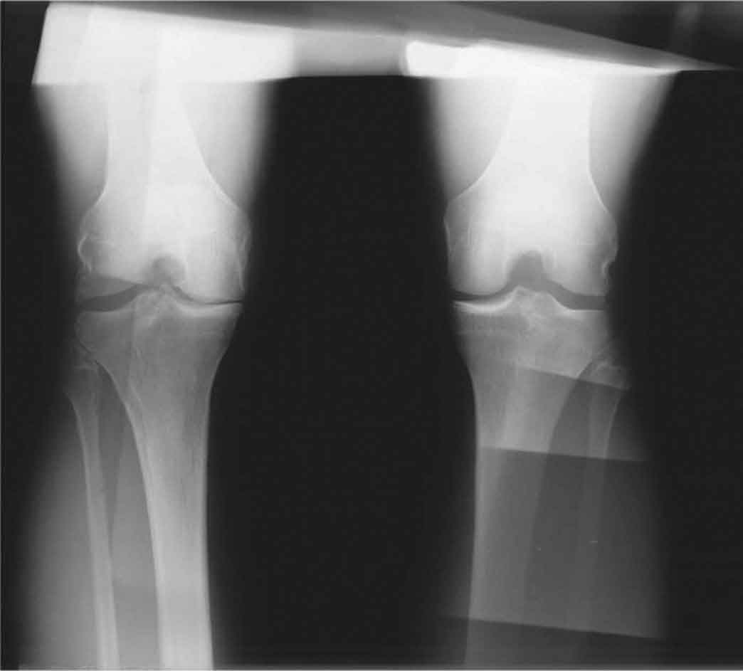
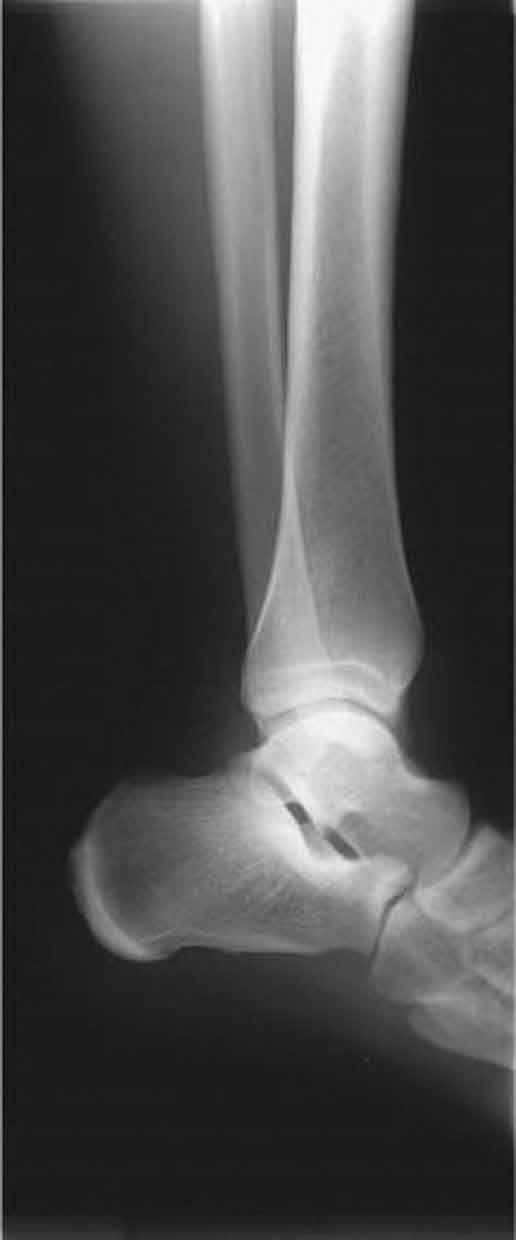
For healthcare professionals involved in the primary management of neuromusculoskeletal disorders, diagnostic imaging is an essential tool. The availability of diagnostic images to physical therapists greatly depends on the practice setting. For example, physical therapists in the United States army have had privileges for ordering diagnostic imaging procedures since the early 1970s.1 Outside of the United States military health system, few published examples describe civilian-sector practice models that include physical therapists referring patients directly for imaging tests.2 The role of imaging based on the Physical Therapy Practice Act language for the 50 states and the District of Columbia reveals tremendous variability, ranging from “prohibiting the use of roentgen rays for any purpose” to the prohibition of physical therapists from referring patients for diagnostic imaging, to being “silent” on the issue.2 This is somewhat surprising given the drive to pass patient direct access to physical therapy services, as the ability to directly refer patients to other providers, including a radiologist, would seem paramount.3 At the heart of the issue is whether physical therapists are adequately educated regarding appropriate imaging referral. Although Springer et al.4 demonstrated that military physical therapists were as competent as orthopedists in the utilization of the modified Ottawa ankle rules (determining whether ankle-foot radiographs are indicated for patients post ankle injury), the participating physical therapists had completed an advanced training program.3 With regard to those physical therapists trained in the civilian sector, the advent of Doctor of Physical Therapy (DPT) degree programs has resulted in increased emphasis on imaging as a content area in these degree programs, although it is difficult to find publications that describe current imaging curricular within these programs.3 Boissonnault et al.3 performed a descriptive survey to describe the status of diagnostic and procedural imaging curricula within the United States physical therapist professional degree programs and found that, while the majority of programs reported including imaging curricula, variability was noted in all curricular aspects. Although the ordering of imaging studies is not currently within the scope of many physical therapy practices, clinicians frequently request or receive imaging study reports. Although the interpretation of diagnostic images is always the responsibility of the radiologist, it is important for the clinician to know what importance to attach to these reports, and the strengths and weaknesses of the various techniques that image bone and soft tissues, such as muscle, fat, tendon, cartilage, and ligament. In general, imaging tests have a high sensitivity (few false negatives) but low specificity (high false-positive rate), so are thus used in the clinical decision-making process to test a hypothesis but should not be used in isolation. In addition, imaging studies are expensive and somewhat more invasive compared to a physical examination, so the clinician must weigh the relative value of recommending an imaging study in relation to the working hypothesis. For example, when there is little likelihood that imaging will reveal anything that will change the course of treatment, the tests should be considered unnecessary.1 In addition, the clinician needs to understand that the results of an imaging study may not correlate with the results of the physical examination. Although imaging may provide evidence of pathology, the mere presence of the abnormality may or may not be relevant to the presenting signs and symptoms. In such situations, the clinician should place no more or less weight on the imaging results than on other aspects of the decision-making process. In 1895, Wilhelm Conrad Röntgen was experimenting with a type of electrical tube that produced an electrical discharge when a high voltage current was passed through it.5 When Röntgen shielded the tube with heavy black cardboard, he noticed that a fluorescent screen a few feet away lit up and glowed indicating that some form of energy was passing through the tube. Further experiments led Röntgen to discover that these energy waves could reliably reproduce images of the human skeleton on a glass photographic plate.5 Röntgen named these energy waves x-rays because “x” was the unknown quantity in a mathematical equation, and he was unsure of what the rays were composed of.5 In 1896, Henri Becquerel discovered the basic nature of radiation and almost immediately an article appeared in the Journal of the American Medical Association theorizing on the possible diagnostic and therapeutic uses of this new discovery.5 X-rays were soon determined to be part of the electromagnetic spectrum with the ability to penetrate through body tissues of varying densities. It was also discovered that the amount of beam absorbed as it passed through the body depended on the density of the tissue. This allowed physicians to use the images to view a number of anatomical structures. Initially, only small segments of the body could be radiographed in a single exposure—studies of large, thick body parts such as the abdomen, and hip could not be adequately covered. Then, in 1912, Dr. Gustav Bucky published his findings describing a stationary, cross-hatched or “honey-combed” lead grid, which helped absorb scatter radiation and thus enhanced image quality. The grid consisted of wide strips of lead arranged in two parallel series that intersected at right angles. One disadvantage of the stationary grid is that the lead strips left “blank” or white lines on the film (“grid lines”). A few years later, Dr. Hollis Potter introduced a multi-leafed focused grid, which moved the grid sideways across the film during the exposure, thereby blurring out the shadows of the grid strips, and further enhancing the image quality. Over the years, various mechanisms have been utilized to achieve this movement. Two physical factors responsible for grid efficiency are the grid ratio and the grid frequency. Grid selection involves a compromise between film quality and patient exposure. High-ratio grids produce films with better contrast at the cost of increased patient exposure; however, proper alignment is more critical. Conventional (plain film) radiography is generally considered to be the first-order diagnostic imaging modality.6 The basic process is fairly simple. The patient’s body part of interest is oriented in a prescribed position and the film plate, receptor or, detector is positioned to capture the particles of the x-ray beam that are not absorbed by the tissues of the body. Both sides of the film are thinly coated with a fluorescent gel, and then the film is placed within a two-layered hard plastic shell, which protects the film and allows easy portability. An x-ray machine then directs electromagnetic radiation upon the specified region of the body. Tissues of greater density allow less penetration of the x-rays and, therefore, appear lighter on the film. A difference in radio density is necessary for two structures to appear different on resultant radiographs. The following structures are listed in order of descending density: metal, bone, soft tissue, water or body fluid, fat, and air. Because air is the least dense material in the body, it absorbs the least amount of x-ray particles, resulting in the darkest portion of the film. Bones can have varying densities within the body. For example, cancellous bone is less dense than cortical bone and thus appears lighter than the cortical bone on the radiograph. Soft tissues often cannot be separated because they have similar radio densities. Numerous technical factors are manipulated and equilibrated in order to produce a high-quality diagnostic image while keeping the radiation dose as low as possible. Long focal film distances, short object film distances, small focal spots, short exposure time, tight collimation (the process of restricting and confining an x-ray beam to a given area), and optimal film/screen combinations can all be used to enhance the image.7 Reducing radiation exposure to the lowest levels may be addressed by attention to details of patient centering, shielding, and collimation, reducing repeat films, and the timely calibration of x-ray equipment.7 Digital radiography exists in the form of computed radiography or direct radiography. Image processing and distribution is achieved through a picture archiving and communication system. However, the spatial resolution of digital radiography systems is not yet as great as that with film screen radiography.8 Plain-film, or conventional, radiographs are relatively inexpensive and give an excellent view of cortical bone (Figs. 7-1 to 7-7). Radiographs may be more specific than MRI in differentiating potential causes of bony lesions because of the proven ability to characterize specific calcification patterns and periosteal reactions.1 Plain radiographs are not considered sensitive to the early changes associated with tumors, infections, and some fractures.9 However, they can be very helpful in detecting fractures and subluxations in patients with a history of trauma.10 Radiographs may also be used to highlight the presence of degenerative joint disease, which is characterized by an approximation of the joint surfaces on the radiograph. However, radiographs do not provide the most accurate image of soft tissue structures, such as muscles, tendons, ligaments, and intervertebral disks (IVDs). FIGURE 7-1 Radiograph showing abnormal bone growth of femur. FIGURE 7-2 Radiograph showing an extensive history of ACL reconstructions. FIGURE 7-3 Radiograph showing grade I Salter–Harris fracture of the fibula. FIGURE 7-4 Radiograph following medial wedge osteotomy of the right knee. FIGURE 7-5 Radiograph following ACL reconstruction (allograft) of the right knee. FIGURE 7-6 Radiograph showing end-stage medial compartment degeneration (Varus malalignment) of the right knee. FIGURE 7-7 Radiograph showing right ankle avulsion fracture/deltoid sprain. Radiographs are a 2D representation of a 3D structure. During the initial exposure to reading radiographs, it is important that the clinician examines as many “normal” radiographs as possible. There is a great deal of variations in the human body and a great deal of variations in what is considered to be normal. When evaluating radiographs, a systematic approach such as the mnemonic ABCS is recommended11: For all joints and regions, there are a number of standard, or routine, radiographic series that are typically obtained.13 A radiographic series is a group of x-rays films, taken from one area of the body, from different angles. These groups of films have been standardized by long years of experience and standards of care to provide all the needed information about an area of interest. For example, a standard chest x-ray uses certain established angles and amounts of radiation to enhance the view of the soft tissues of the heart and lungs, whereas a rib series uses an entirely different set of angles and radiation to bring out the bony detail with more clarity. In addition to the standard series, there are also additional or special views that can be ordered to visualize a particular structure more effectively (Table 7-1).13 For example, a patient presenting with pain in the “anatomic snuffbox” area of the wrist may have a fracture of the scaphoid bone, requiring a special view of the area rather than a standard wrist series. It is important that the clinician has an appreciation of various views and what each represents. TABLE 7-1 Standard and Special Radiographic Views Region Common Views/Special Views Patient Position Purpose and Structures Imaged Shoulder complex A-P, external rotation The patient is supine or erect, preferably erect, and slightly oblique, so the scapula is near parallel to the film. The forearm is supinated with a slight abduction of the shoulder for external rotation, and the elbow is slightly flexed. Central ray perpendicular to the coracoid process Anatomic position of the shoulder girdle with the greater tuberosity seen in profile, laterally. The glenohumeral and acromioclavicular joints, proximal humerus, clavicle, and portions of scapula can all be viewed in this position A-P, internal rotation The patient is positioned as for external rotation except that the back of the hand rests on the hip. Central ray is perpendicular to the coracoid process Provides approximately 90-degree opposing view to anteroposterior, external rotation including a true lateral of the humerus with the lesser tuberosity seen in profile, medially Axillary Has many variations but essentially consists of the x-ray beam passing through the axilla from inferior to superior. The West Point axillary view is obtained with the patient prone and the tube angled 25 degrees cranially and medial to the midline of the glenohumeral joint. The Stryker notch view is taken with the patient supine and the arm flexed (without abduction), and the cassette beneath the shoulder. The central ray is directed 10 degrees cranially The glenohumeral joint, coracoid process, and the acromion process can be seen in addition to the humeral head position with respect to glenoid fossa West Point view maximizes visualization of the anterior inferior glenoid rim, enhancing the detection of bony Bankart lesions Stryker notch view: maximizes the visualization of the humeral head and Hill–Sachs lesions A-P, lateral scapula Transscapular or Y view Useful in identifying fractures of scapula Entire scapula; best view for comminuted and displaced fractures of the scapula Acromioclavicular joints A-P The patient is erect with the arms hanging at the sides. The central ray is 15 degrees cranially at the level of the coracoid process. A bilateral frontal projection of the AC joint Stress As above except with 10–20 lb weight strapped (if the patient holds the weight, the resulting muscle contraction may produce a false-negative) to the patient’s wrist Helps differentiate incomplete from complete injuries Sternoclavicular P-A The patient is positioned in prone. The central ray is perpendicular to the midpoint of the body at the level of the sternoclavicular joints A frontal view of the sternoclavicular joints and medial aspects of the clavicles. Serendipity The patient is supine or erect, facing the tube. A 40-degree cranial tilt of the central ray Allows for evaluation of anterior and posterior dislocation Elbow A-P The elbow is extended with the forearm supinated and the patient leaning laterally until the anterior surface of the elbow is parallel with the plain x-ray cassette of the film. Central ray is perpendicular to the elbow joint An A-P projection of the elbow joint including the distal end of the humerus, the humeroulnar and humeroradial joints, and the proximal end of the forearm Lateral The elbow is flexed 90 degrees and the hand is in a lateral position. Central ray is perpendicular to the elbow joint Integrity of olecranon articulation with olecranon fossa; look for fat pad signs Epicondylar groove (cubital tunnel) This view is an axial view, modified by 15 degrees of external rotation Used to determine whether there is bony encroachment on the cubital tunnel, contributing to ulnar nerve entrapment Radial head-capitellum Obtained in the same position as a lateral view with the primary beam angled 45 degrees toward the shoulder and centered on the radial head Best view of radial head, capitellum, and coronoid process Forearm A-P, lateral Both views include the elbow and the wrist, and both views are centered on the midshaft of the forearm bones Entire radius and ulna, wrist, elbow Wrist P-A Forearm and hand on x-ray cassette with palmar surface down; the hand is slightly arched, placing the wrist in close contact with the film. Central ray perpendicular to the midcarpus P-A projection of all carpals, the distal end of the radius and ulna, and the proximal ends of the metacarpals, carpal alignment Lateral Elbow flexed 90 degrees, the forearm and arm on the x-ray cassette are ulnar side down. Central ray perpendicular to the carpus Lateral view of the carpus, the proximal end of the metacarpals and the distal end of the radius and ulna highlighting posterior (dorsal)/volar relationships Posterior oblique From the lateral position, the forearm is pronated until the wrist forms an angle of approximately 45 degrees with the plane of the film. The central ray is perpendicular to the scaphoid Demonstrates the carpal bones on the lateral side of the wrist, in particular the scaphoid. In addition the first metacarpal, thumb carpometacarpal joint, and trapezium can be viewed Hand P-A Forearm and hand on x-ray cassette with palmar surface down. Central ray perpendicular to the third metacarpophalangeal joint P-A view of the carpals, metacarpals and phalanges (except the thumb), and the distal ends of the radius and ulna. This position yields an oblique view of the thumb. A true anterior–posterior projection of the thumb is obtained by turning the hand into a position of extreme internal rotation and holding the extended fingers back with the opposite hand, with the posterior (dorsal) surface of the thumb resting on the x-ray cassette Lateral Forearm and hand on x-ray cassette, ulnar side down with fingers superimposed. Central ray perpendicular to the MCP joints Lateral view of the bony and soft tissue structures highlighting the posterior (dorsal)/volar relationships so that anterior and posterior displacement of fracture fragments can be seen Posterior oblique Forearm and hand on x-ray cassette, ulnar side down with the forearm pronated so that the fingers, which are slightly flexed, touch the cassette and the MCP joints form an angle of approximately 45 degrees. Central ray perpendicular to the third MCP joint Oblique view of the bone and soft tissue of the hand. With a slight adjustment of this position, a true lateral of the thumb can be obtained Hip A-P pelvis Patient supine with the feet internally rotated 15 degrees (to eliminate overlay of the greater trochanter). Central ray perpendicular to the midpoint of the film Frontal projection of the entire pelvis, both hips and proximal femurs Lateral-oblique (frog-leg) The patient is turned to a near lateral position and toward the affected side with the hip and knee flexed. A straight tube is centered on the femoral head Extremely valuable for examining the femoral head and neck, especially to exclude fractures and to assess the apophysis and femoral capital epiphysis in the immature patient Knee A-P Patient supine with the knee extended. Central ray 5–7 degrees cranial to the knee joint Frontal view of the tibiofemoral joint space and articular surfaces; distal femur; proximal tibia Lateral Lateral with the affected side down and the knee flexed approximately 30 degrees. The central ray is 5 degrees cranial Lateral view of the patellar position, distal femur; proximal tibia and fibula Sunrise axial The patient is positioned in prone and the knee is flexed more than 90 degrees. The beam is angled perpendicular to the x-ray cassette Patellofemoral joint and medial/lateral positioning of patellar; intercondylar groove Intercondylar The patient is positioned kneeling on the table with the knee flexed to 70 degrees and the beam centered on the inferior pole of the patella Intercondylar fossa, notch of popliteal tendon, tibial spines, intercondylar eminence, posterior aspects of the distal femur and proximal tibia, intercondylar eminence of tibia Merchant The patient is supine and the knees are flexed over the end of the x-ray cassette. The beam is directed toward the feet and the film cassette is held on the shins Patellar, femoral condyles. Preferred view of articular surface of the patellar, subtle dissertations Ankle A-P The patient is positioned in supine with the foot vertical. The central ray perpendicular to a point midway between the malleoli Frontal projection of the ankle joint, the distal end of the tibia and fibula, and the proximal portion of the talus. Neither the syndesmosis nor the inferior portion of the lateral malleoli is well demonstrated in this projection Mortise Supine with the leg and foot rotated internally approximately 15 degrees. The central ray perpendicular to the ankle joint The syndesmosis is well seen without overlap of the anterior process of the distal tibia; best view of mortise and distal aspect of the lateral malleolus Lateral Lateral side of the ankle down; the patient is supine and turned toward the affected side. The central ray is perpendicular to the lateral malleolus A lateral view of the distal third of the tibia and fibula, the ankle joint, talus, calcaneus, and the hind foot Impingement The ankle is positioned in extreme plantar flexion to detect posterior impingement, and weight bearing and maximum dorsiflexion to detect anterior impingement To assess bony contribution to posterior or anterior impingement Oblique tarsal The ankle is positioned to provide an oblique view of the foot Best view to detect a fracture of the anterior process of the calcaneus, but can also demonstrate fractures of the base of the fifth metatarsal Inversion stress Best performed with a calibrated standardized device needed to position and stress the ankle Check for lateral instability Eversion stress Best performed with a calibrated standardized device needed to position and stress the ankle Check for medial instability Foot Dorsoplantar Patient supine with the knee flexed and the sole of the foot resting on the x-ray cassette. Central ray is perpendicular to the base of the third metatarsal A frontal projection of the tarsals, metatarsals, and phalanges; tarsometatarsal, metatarsophalangeal, and interphalangeal joints Lateral Lateral side down with the patient supine. The central ray is perpendicular to the midfoot A true lateral projection of the talocrural, subtalar, transverse, and tarsometatarsal joint; hind foot, midfoot, and forefoot relationships Medial oblique Supine with the knee flexed and the leg rotated medially until the sole of the foot forms an angle of 30 degrees to the plane of the film. The central ray is perpendicular to the midfoot The calcaneocuboid, cuboid-fourth and fifth metatarsal, cuboid cuneiform, and talonavicular articulations Less overlap of tarsals than anteroposterior Good view of sinus tarsi Harris Beath (axial) view of the hind foot The patient is positioned in sitting on the x-ray table, leg extended, and the heel resting on the cassette. The ankle is extended and held in this position by the patient applying traction to the forefoot with a bandage or strap. A 45-degree cranial tube angle is used with the primary beam entering the sole of the foot at the level of the base of the fifth metatarsal Best shows the articular surfaces of both the posterior and medial subtalar joints, coalition at the medial facet, and avulsions fractures at the medial or lateral aspects of the calcaneal tuberosity Cervical spine A-P The patient is placed either supine or erect. The central ray is 15–20 degrees cranial at the most prominent point of the thyroid cartilage A frontal view of the C3–C7 vertebral bodies, and the upper two or three thoracic bodies, the interpedicular spaces, the superimposed transverse and articular processes, the uncinate processes, and the intervertebral disk spaces Lateral The patient is lateral to the x-ray cassette, either seated or standing. The central ray is perpendicular to the midneck A lateral view of the C1–C7 vertebral bodies, disk spaces, the articular pillars, spinous processes, and the lower five facet joints. Depending on how well the shoulders can be depressed, the seven cervical vertebrae and sometimes the upper one or two thoracic vertebrae can be seen; all seven cervical vertebrae, particularly in trauma cases, must be seen A-P obliques Obtained by rotating the entire patient 45 degrees one way and then the other, obtaining images in each position Provides information on the neural foramen and posterior elements of the cervical spine. Best view for detecting osteoarthritic encroachment of the intervertebral foramina A-P open mouth The patient’s head is positioned in slight extension to prevent the front teeth from being superimposed over the odontoid Anteroposterior view of C1–C2 articulation. Fractures of C1 and arthritic changes at the C1–C2 facets may also be identified Flexion/extension laterals Obtained by asking the patient to flex and then extend the neck, obtaining images in each position Stress films to check for instability that may not be detected on routine neutral views Pillar An A-P view taken with 20–30 degrees of caudal tube angulation, with a pad under the upper thoracic spine to elevate the shoulders and to allow extension of the cervical spine Shows the articular pillars or lateral masses to advantage as the central beam is angulated parallel to their sloping course, caudad in the A-P projection, and cranial in the P-A projection. Occult fractures may be detected with this view Swimmers view Obtained by positioning the patient so that one arm is raised above their head and the other is by their side like a freestyle swimmer Best view of C7–T2, prevents obstruction by shoulders. Proximal humerus, lateral clavicle, AC joint, superior lateral aspect of the scapula Thoracic spine A-P Obtained with the patient in the supine position, arms by the side and shoulders at the same level. The knees are slightly flexed to reduce the dorsal kyphosis and the beam is sent to 10 cm below the sternal notch T1–T12 vertebral end plates, pedicles, and spinous processes; intervertebral disk spaces; costovertebral joints; medial aspect posterior ribs Lateral The patient is positioned standing side-on, with the shoulder just touching the Bucky for support. The arms are extended and the patient’s balance is stabilized. The film is centered on T7 T1–T12 vertebral end plates, pedicles, spinous processes; intervertebral disk spaces and foramina Posterior oblique The patient is positioned with their back against the bucky, and then rotated posteriorly so they are angled 45 degrees with the affected side touching the bucky. The arm on the affected side is positioned so that it is away from the area of interest (either out to the side, or over the patient’s head) Facet joints, pedicles, and the pars interarticularis Anterior oblique The patient is positioned with their back against the bucky, and then rotated anteriorly so they are angled 45 degrees with the affected side touching the bucky. The arm on the affected side is positioned so that it is away from the area of interest (either out to the side, or over the patient’s head) Sternum, axillary portion of the ribs Lumbar spine A-P or posteroanterior Either frontal projection is adequate and can be taken with the patient supine or erect with patient comfort dictating the position. If the patient is supine, the knees and hips should be flexed. The central ray is perpendicular to L3 A frontal view of the L1–L5 vertebral bodies, pedicles, disk spaces, the lamina, and the spinous and transverse processes. The Ferguson view is an A-P view with a cranial angulation, which essentially compensates for the normal lordosis of the lumbosacral region, and allows one to see the junction clearly Lateral Supine or erect. If supine, the left side is down with the hips and knees flexed to a comfortable position. The central ray is perpendicular to L3 A lateral view of the lumbar vertebral bodies and their disk spaces, the spinous processes, the lumbosacral junction, sacrum and coccyx, the intervertebral foramina, and the pedicles Obliques The patient is positioned in supine with their body angled 30–45 degrees Not only shows the neural foramina but also demonstrates the pars interarticularis to aid in the detection of spondylolysis; best view of facet joints L5–S1 (coned down lateral) spot view The patient is positioned standing in a lateral position with the arms across the chest Lateral of L4–S1 vertebral bodies and disk spaces Flexion–extension The patient is positioned standing side-on and is asked to flex and extend the lumbar spine. An image is taken at each position May enhance spondylolisthesis or retrolisthesis or demonstrate pivotal motion at a given disk Sacroiliac joint A-P axial, obliques The patient is positioned in standing, with the affected side rotated 20–30 degrees away from the film. A-P images bilateral sacroiliac joints; obliques image unilateral sacroiliac joint Pelvis A-P Supine with the feet internally rotated approximately 15 degrees. Central ray perpendicular to the midpoint of the pubic symphysis A frontal view of the pelvic girdle and proximal third of both femora Oblique Also called the bilateral “frog-leg” position, and the patient is positioned accordingly for a bilateral view Detection of acetabular and pubic rami fractures Inlet Patient supine and the beam angled 10 degrees cranially Outlet Patient supine and the beam angled 15 degrees caudad Internally rotated: an anterior oblique view or obturator oblique view is obtained which demonstrates the iliopubic (anterior) column and the posterior lip of the acetabulum Judet Patient positioned so that the injured side is rotated 45 degrees internally and externally Externally rotated: a posterior oblique view or iliac oblique view is obtained which shows the ilioischial (posterior) and the anterior acetabular rim A-P, anteroposterior; P-A, posteroanterior. Data from Shankman S. Conventional radiography and tomography. In: Spivak JM, Di Cesare PE, Feldman DS, et al., eds. Orthopaedics: A Study Guide. New York, NY: McGraw-Hill, 1999:173–178; Barr JB. Medical screening for the physical therapist: Imaging principles. In: Wilmarth MA, ed. Medical Screening for the Physical Therapist. Orthopaedic Section Independent Study Course 14.1.1. La Crosse, WI: Orthopaedic Section, APTA, Inc., 2003:1–15; Deyle G. Diagnostic imaging in primary care physical therapy. In: Boissonnault WG, ed. Primary Care for the Physical Therapist: Examination and Triage. St Louis, MD: Elsevier Saunders, 2005:323–347. Radiographs, like all medical procedures, have risks and benefits. Ionizing radiation can increase the risk of cancer, and in sufficient doses can cause death.14 In addition to the health risks, the overutilization of radiologic studies has become a significant economic problem in the United States.15 For these reasons, there has been an increased need for clinical prediction or decision rules indicating a need for radiography for specific types of injury in certain areas of the body. A clinical decision rule (CDR) is a tool that can quantify individual contributions from the components of the examination to determine the diagnosis, prognosis, or treatment for a given patient.1 CDRs for reevaluation of cervical spine injuries remain controversial, although consensus exists that cervical radiographic studies are over-utilized in the emergency department (ED).16 In addition to the routine projections of the cervical spine, the anteroposterior (A-P) and lateral views, a number of other views can be used to aid in the evaluation of trauma and arthritis (Table 7-1). The A-P view provides information about the shape of the vertebra, the presence of any lateral wedging or osteophytes, and the disk space. In the lower cervical spine, the A-P view can also provide information about the presence of a cervical rib. The lateral view provides information about the lordosis and general shape of the cervical curve and cervical vertebrae. This view also provides information about any anterior or posterior displacement of the vertebrae, the size of the disk space, the integrity of the vertebral edges (lipping), facet subluxation, soft tissue abnormalities, and the presence of any osteophytes. By measuring the prevertebral soft tissue width at the anteroinferior border of the C-3 vertebra, a determination is made as to the existence of edema or hemorrhage if the width is wider than the normal 7 mm.17
CHAPTER 7
Imaging Studies in Orthopaedics
OVERVIEW
Radiography
 Grid ratio: The height of the lead strip in relationship to the distance between them. Example: A 10:1 grid has lead strips 10 mm high, and these strips are 1 mm apart. The strips are ten times as tall as the distance between them.
 Grid frequency: Defined as the number of lead strips per centimeter (or per inch). The greater the frequency, the thinner the strips, and the greater the likelihood of scattered photons passing through.
 A: Architecture or alignment. The entire radiograph is scanned from top to bottom, side to side, and in each corner to check for the normal shape and alignment of each bone. The outline of each bone should be smooth and continuous. Breaks in continuity usually represent fractures. Malalignments may indicate subluxations or dislocations, or in the case of the spine, scoliosis. Malalignment in a setting of trauma must be considered traumatic rather than degenerative until proven otherwise.7
 B: Bone density. The clinician should assess both general bone density and local bone density. The cortex of the bone should appear denser than the remainder of the bone. Subchondral bone becomes sclerosed in the presence of stress in accordance with Wolff’s law12 and increases its density. This is a radiographic hallmark of osteoarthritis.
 C: Cartilage spaces. Each joint should have a well-preserved joint space between the articulating surfaces. A decreased joint space typically indicates that the articular cartilage is thinned from a traumatic process or a degenerative process such as osteoarthritis.
 S: Soft tissue evaluation. Trauma to soft tissues produces abnormal images resulting from effusion, bleeding, and distension.
Clinical Applications
Cervical Spine
Imaging Studies in Orthopaedics
