I. Introduction—Fractures of the acetabulum generally occur in younger individuals as a result of high-energy motor-vehicle accidents. Radiographic analysis and classification of displaced acetabular fractures by Letournel’s classification allows the surgeon to choose better the appropriate surgical approach. Displaced fractures of the acetabulum require operative anatomic reduction. Incongruity of the acetabulum, even as small as 1 mm, results in posttraumatic arthritis characterized by erosion of the femoral head and loss of articular cartilage. This condition is often misdiagnosed as avascular necrosis, which is characterized by collapse of the femoral head with maintenance of the joint space.
II. Bony Anatomy—The acetabulum is part of the innominate bone and is formed by the ilium, ischium, and pubis. Letournel described the acetabulum as an inverted “Y” with anterior and posterior columns (Fig. 16-1). The anterior column includes the pelvic brim, anterior wall, superior pubic ramus, and anterior border of the iliac wing. The posterior column includes the greater and lesser sciatic notch, posterior wall, ischial tuberosity, and most of the quadrilateral surface.
III. Radiographic Evaluation
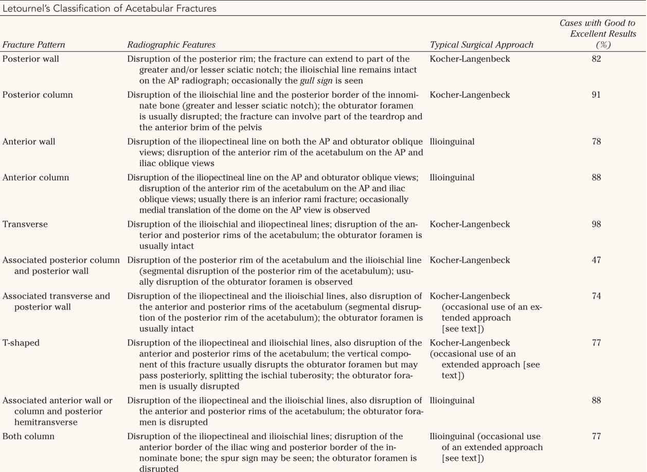
A. Views and Radiographic Landmarks—Radiographic evaluation includes the following views: anteroposterior (AP) (Fig. 16-2A), 45° obturator oblique (Fig. 16-2B), and the 45° iliac oblique (Fig. 16-2C). Six radiographic lines on the AP radiograph represent the tangency of the X-ray beam to the pelvis, not necessarily the anatomic landmarks (Table 16-1). Disruption of the normal radiographic lines represents a fracture to that area of bone. The anatomic area responsible for each line is described in Table 16-1. For a fracture to be truly nondisplaced, no displacement of the radiographic landmark must be seen on at least two of the three radiographic views.
B. The 45° Oblique Views—The 45° obturator oblique radiograph is taken with the fractured acetabulum rotated toward the X-ray beam, showing the obturator foramen and profiling the anterior column medially and the posterior wall laterally (Fig. 16-2B). The 45° iliac oblique radiograph is taken with the fractured acetabulum rotated away from the X-ray beam, showing the iliac wing and profiling the posterior column (greater and lesser sciatic notch) medially and the anterior wall laterally (Fig. 16-2C).
C. Analysis of the Fractured Acetabulum
1. Incongruency—Besides fracture displacement, congruency of the femoral head within the acetabulum is analyzed. Subtle anterior subluxation can be seen on the obturator oblique view, and subtle posterior subluxation can be seen on the iliac oblique view (medialization of the femoral head with respect to the dome of the acetabulum). Comparing the injured side with the unaffected side on the AP and 45° oblique views of the pelvis helps detect any incongruency. Minimally displaced fractures of the acetabulum can be diagnosed by detecting these subtle subluxations of the femoral head.
2. Roof arc measurements—Roof arc measurements are defined as the angle formed by a line parallel to the patient passing through the center of the acetabulum and a line from the center of the acetabulum to the fractured area of the dome. The medial roof arc (MRA) measurement is made on the AP radiograph (Fig. 16-3), the anterior roof arc (ARA) measurement is made on the obturator oblique radiograph (Fig. 16-4), and the posterior roof arc (PRA) measurement is made on the iliac oblique radiograph (Fig. 16-5). Roof arc measurements of 45° correspond roughly to 10 mm of the dome on a computed tomography (CT) scan (Fig. 16-6). These roof arc measurements are used for making decisions for surgery and are important in T-shaped and transverse fractures (see Treatment section).
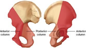
FIGURE 16-1 Delineation of the anterior and posterior columns of the acetabulum on the inner (left) and outer (right) aspects of the innominate bone.
D. CT Scan—Congruency of the femoral head in the acetabulum and classification of the fracture type can usually be performed with plain radiographs alone. CT is useful in defining: posterior pelvic injuries (e.g., sacroiliac joint, sacral fractures), fractures of the quadrilateral surface, marginal impactions of the posterior wall, rotation of the articular pieces, and intraarticular free fragments. The CT scan is used to classify fractures by looking at the orientation of fracture planes. Vertical fracture planes on CT correspond to transverse or T-shaped fractures, and horizontal lines correspond to column fractures (Fig. 16-7). Three-dimensional CT can provide a useful overall picture of the fracture configuration, but because of smoothing artifacts in the computer reconstructions, nondisplaced fractures and fractures in the plane of the CT scan can be missed. Computer systems that can remove the femoral head from the images are more useful for evaluation of the acetabulum.
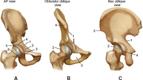
FIGURE 16-2 Normal radiographic landmarks of the acetabulum. A. AP radiographic view. 1, Iliopectineal line; 2, ilioischial line; 3, radiographic U, or teardrop; 4, acetabular roof; 5, anterior rim of the acetabulum; 6, posterior rim of the acetabulum. B. Obturator oblique view. 1, Iliopectineal line; 2, posterior rim of the acetabulum; 3, obturator foramen; 4, anterior superior iliac spine. C. Iliac oblique view. 1, Posterior border of the innominate bone; 2, anterior rim of the acetabulum, 3, anterior border of the iliac wing; 4, posterior rim of the acetabulum.
IV. Classification—Letournel’s classification of acetabular fractures (Fig. 16-8 and Table 16-2) separates the fractures into simple fractures (posterior wall, posterior column, anterior wall, anterior column, and transverse fractures) and complex associated fracture patterns that combine two of the simple patterns (associated posterior column and posterior wall, associated transverse and posterior wall, T-shaped, associated anterior wall or column and posterior hemitransverse, and both column).

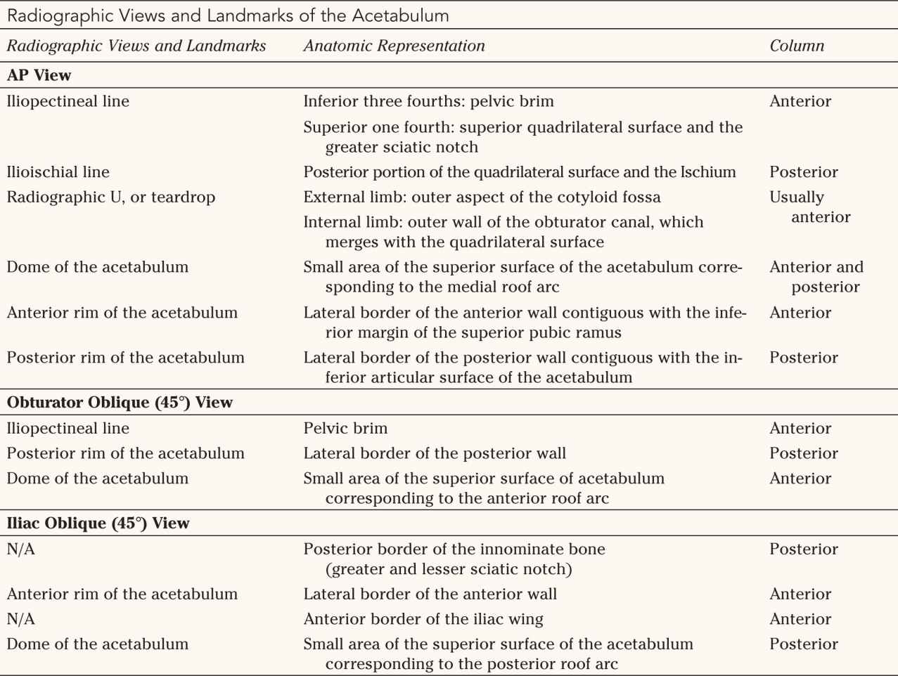
N/A, Not Applicable (no named radiographic landmark has been described).

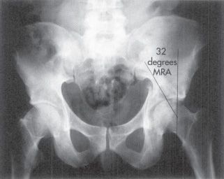
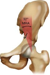
FIGURE 16-3 The medial roof arc angle is formed by a line passing through the center of the acetabulum parallel to the patient and another line from the center of the acetabulum medially to the fractured dome as seen on an AP radiograph. The angle in this case is 32°.
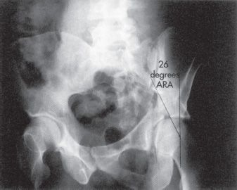
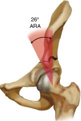
FIGURE 16-4 The anterior roof arc angle is formed by a line passing through the center of the acetabulum parallel to the patient and another line from the center of the acetabulum medially to the fractured dome as seen on the obturator oblique radiograph. The angle in this case is 26°.
1. Posterior wall fractures (Figs. 16-8 and 16-9 and Table 16-2)—Posterior wall fractures involve various amounts of the articular and retroacetabular surfaces. Posterior wall fractures have displacement of the posterior rim line on both the AP and obturator oblique views. The fracture may involve the greater and lesser sciatic notch, but the ilioischial line on the AP view remains intact. Occasionally, a gull sign is present where the displaced posterior wall remains hinged medially, with superior and posterior displacement of the lateral aspect of the posterior wall giving the appearance of a gull wing (Fig. 16-9).
2. Posterior column fractures (Fig. 16-8 and Table 16-2)—Posterior column fractures involve the ischial retroacetabular surface. The fracture line exits the bone in the greater sciatic notch, traverses the articular surface, and usually exits through the obturator foramen and the inferior pubic ramus. Occasionally, the fracture line runs vertically, splitting the ischial tuberosity, without entering the obturator foramen. Depending on the size of the posterior column fragment, the fracture may involve part of the teardrop or brim of the pelvis anteriorly.
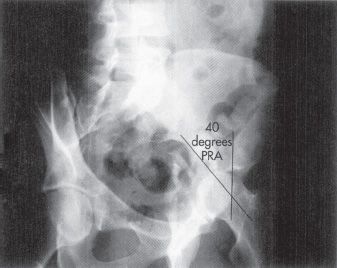
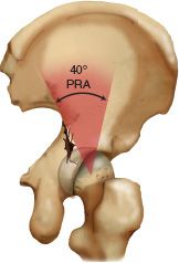
FIGURE 16-5 The posterior roof arc angle is formed by a line passing through the center of the acetabulum parallel to the patient and another line from the center of the acetabulum medially to the fractured dome as seen on the iliac oblique radiograph. The angle in this case is 40°.
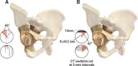
FIGURE 16-6 CT scan of the acetabular dome. A. This right acetabulum illustrates the location of the three acetabular roof arcs. These arcs are lines representing the portion of the subchondral bone tangent to the X-ray film in the AP, obturator oblique, and iliac oblique views. The anterior roof arc begins at the posterior lip of the acetabulum, crosses the vertex and extends to the anteroinferior articular surface. The medial and posterior arcs begin at the mid and anterior lip of the acetabulum, cross the vertex, and extend to the acetabular fossa and posteroinferior articular surface, respectively. The inset illustrates a globe with three arcs at 45° intervals, shown from above and obliquely. These lines are analogous to three lines of longitude on a globe 45° apart. B. The line shown in the acetabulum represents the level of the CT image 10 mm inferior to the vertex of the acetabulum. The circle along the subchondral bone 10 mm inferior to the vertex is equivalent to a fracture line for which all three roof arc measurements are 45° in almost all cases. The inset illustrates evaluation of the superior acetabulum by CT to 10 mm inferior to the vertex in 2-mm intervals.
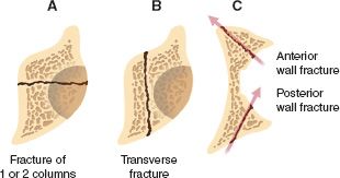
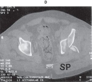
FIGURE 16-7 CT scan cross section. A. A transverse fracture plane represents a column-type fracture. B. A vertical fracture plane represents a transverse-type fracture. C. A 45° oblique fracture plane represents a wall-type fracture. D. CT scan demonstrating an associated transverse and posterior wall fracture.
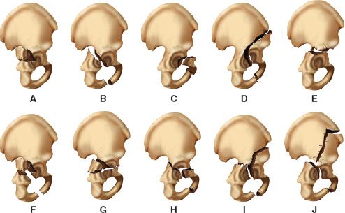
FIGURE 16-8 Classification of acetabular fractures according to Letournel. A. Posterior wall fracture. B. Posterior column fracture. C. Anterior wall fracture. D. Anterior column fracture. E. Transverse fracture. F. Associated posterior column and posterior wall fracture. G. Associated transverse and posterior wall fracture. H. T-shaped fracture. I Associated anterior wall or column and posterior hemitransverse fracture. J. Both-column fracture.
3. Anterior wall fractures (Fig. 16-8 and Table 16-2)—Anterior wall fractures involve the central portion of the anterior column, disrupting the anterior rim of the acetabulum on the AP and iliac oblique views without disrupting the inferior pubic ramus. Disruption of the iliopectineal line occurs on the AP and obturator oblique views.
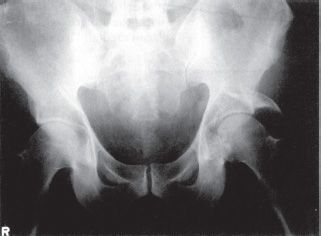
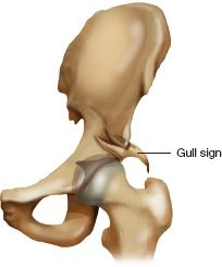
FIGURE 16-9 Gull sign. AP radiograph and drawing of a posterior wall fracture. The displaced posterior wall fracture remains hinged medially, with superior and posterior displacement of the lateral aspect of the posterior wall giving the appearance of a gull wing.


4. Anterior column fractures (Fig. 16-8 and Table 16-2)—Anterior column fractures can exit the bone very high (iliac crest) or very low (superior pubic rami). Disruption of the iliopectineal line on the AP and obturator oblique views occurs with these fractures. The fracture involves the inferior pubic ramus and may be associated with medial translation of the dome on the AP view.
5. Transverse fractures (Fig. 16-8 and Table 16-2)—Transverse fractures divide the acetabulum into two portions. The upper portion contains the roof of the acetabulum, and the lower portion contains a portion of the anterior and posterior wall and an intact obturator foramen (unless the obturator foramen is disrupted by an associated pelvic injury). Letournel subdivided transverse fractures based on where the fracture line traversed the acetabulum: (a) transtectal, the fracture line crosses the articular surface of the superior acetabulum; (b) juxtatectal, the fracture line crosses the junction of the articular surface and the superior cotyloid fossa; and (c) infratectal, the fracture line crosses through the cotyloid fossa. The transverse fracture line crosses both columns, but is not considered a both-column fracture. In transverse fractures, the two columns are not separated from each other. Transverse fractures have disruption of the anterior rim, posterior rim, iliopectineal line, and ilioischial line, but the obturator foramen is usually intact.
B. Complex Fractures—Complex or associated fractures usually combine two of the simple fracture patterns.
1. Associated posterior column and posterior wall fractures (Fig. 16-8 and Table 16-2)—The ilioischial line is displaced from the teardrop, and the iliopectineal line is intact. Even 1 mm of displacement can lead to severe arthrosis.
2. Associated transverse and posterior wall fractures (Fig. 16-8 and Table 16-2
Related posts:

Stay updated, free articles. Join our Telegram channel

Full access? Get Clinical Tree


