Fig. 32.1
Images demonstrating mechanical anterior stress radiographs using a Telos® device. The knee joint is flexed in 90°. The foot is placed in a shoe-like construct, which is fixed on the device providing a neutral position of the ankle joint. While 15 kP pressure is placed on the patella and femur, a dorsal fixation of the lower leg prevents a backward shift. A foam pad is placed underneath the opposite leg to prevent rotation of the examined leg
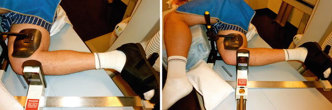
Fig. 32.2
Images demonstrating mechanical posterior stress radiographs using a Telos® device. The knee joint is flexed in 90°. The foot is placed in a shoe-like construct, which is fixed on the device providing a neutral position of the ankle joint. While 15 kP pressure is placed on the tibia; a fixation of the femur prevents shifting. A foam-pad is placed underneath the opposite leg to prevent rotation of the examined leg
The first and second are the clinically most useful ones, as they provide the surgeon with reliable and clinically meaningful findings [15, 27]. However, neither of them is without limitations. The most important one is that, often, the patient does not feel comfortable having the knee stressed and cannot hold this position. Furthermore, the stress radiographs setup is not commonly available. The kneeling view only gives information on the posterior tibial displacement but cannot be used to evaluate anterior displacement. It also has to be emphasized that, under all circumstances, rotational mismatch of the femoral condyles should be avoided when obtaining the radiographs. In the lateral view, the posterior femoral and tibial condyles should perfectly overlap. In our experience, it is necessary to perform the anterior-posterior stress radiographs in 30° and 90° flexion as this represents the clinical testing using Lachman and drawer testing.
The obtained radiographic images are analysed according to a well-established method initially described by Jacobsen in 1976. This method relies on standard bony landmarks [13]. First, a horizontal line defines the tibial plateau position. Then two perpendicular tangent lines, one through the mid-posterior tibial and one through the mid-posterior femoral contours, are drawn. The anterior or tibial posterior displacement is defined by the distance of those two lines on the tibial plateau line.
There are no clear diagnostic cut-off values, but some landmark studies have reported those in particular for patients with an ACL or PCL tear. Although in native knees an anterior translation difference of more than 3 mm and a posterior translation of more than 10 mm (Telos® device, tear >10 mm; side difference of minimum 8 mm; severe or combined lesions >12 mm; normal diff. 0–2 mm; kneeling view, tear 10–18 mm; side-to-side difference 7–14 mm) is considered to be indicative for an ACL or PCL tear, respectively, it is hard to define clear diagnostic cut-off values for patients after TKR [6, 23, 33].
In the PCL kneeling view, 0–2 mm posterior translation is normal, 2–7 mm indicates a partial tear, 8–11 mm a complete tear and >12 mm a combined injury [11].
For the evaluation of varus-valgus stability in extension and flexion, stress radiographs in various degrees of flexion can be performed (Figs. 32.3 and 32.4). In particular, the 90° flexion view could help to detect instability in flexion. Again, it is very difficult to report diagnostic thresholds, but the normal medial and lateral joint space opening under valgus and varus stress is up to 5° [20, 26]. The comparison to the contralateral side is mandatory.
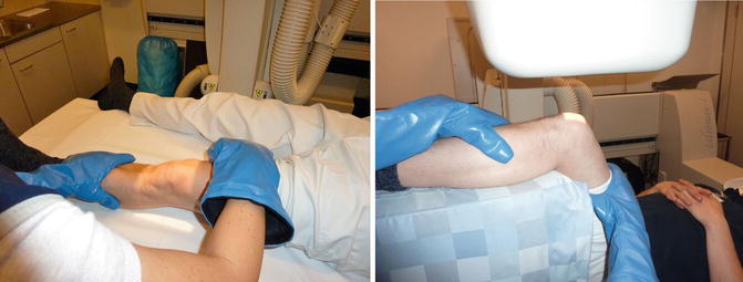
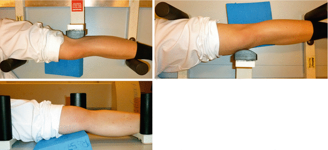

Fig. 32.3
Images demonstrating manual varus-valgus stress radiographs in 30° and 90° flexion. A foam pad is placed underneath the leg to ensure rotational hip joint stability during the stress radiograph

Fig. 32.4
Images demonstrating mechanical varus-valgus stress radiographs in extension using a Telos® device. A foam pad is placed underneath the knee joint to prevent hyperextension
Diagnostic thresholds for varus-valgus stability in extension and flexion stress radiographs: Normal medial and lateral joint space opening under valgus and varus stress is up to 5°. The comparison to the contralateral side is mandatory.
While clinical examination of varus and valgus instability can be well performed in extension, there are difficulties in flexion due to the simultaneous hip rotation. To compensate for this phenomenon, colleagues from the Balgrist Orthopaedic Department at the University Hospital Zürich established a specific technique of fluoroscopy-assisted stress radiographs [32]. For these radiographs, the patient is positioned supine on a radiolucent 3-part board on the fluoroscopy table, which can be adjusted to the individual patient’s anatomy. Alternatively, a foam pad can be placed underneath the leg to gain hip joint stability for the stress examinations (Fig. 32.3). Flexion gap laxity is best evaluated in 80°–90° flexion. Standardized joint opening angles at varus and valgus stress can be measured by drawing tangents on the femoral condyles and the tibial plateau (Fig. 32.5).


Fig. 32.5
Standardised joint opening angles at varus and valgus stress can be measured by drawing tangents on the femoral condyles and the tibial plateau
An example of a slight valgus laxity in 90° flexion is shown in Fig. 32.6 with an increased medial joint space width of 6°. An example of varus laxity in 0° flexion with a lateral joint space width of 10° is shown in Fig. 32.7; in 90° flexion, the laxity is less severe with 6°. Figure 32.8 presents the instrumented varus-valgus stress radiographs using the Telos® device in extension and 30° flexion. Here, an increased lateral joint opening is observed in extension and 30° flexion.
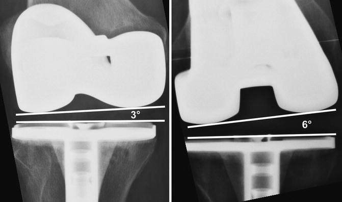

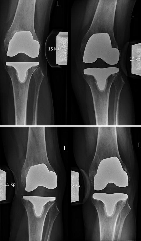

Fig. 32.6
An example of a slight valgus laxity in 90° flexion is shown with an increased medial joint space width of 6°

Fig. 32.7
An example of varus laxity in extension with a lateral joint space width of 10° is shown. In 90° flexion, the laxity is less severe (6° lateral joint space opening)

Fig. 32.8
Instrumented varus-valgus stress radiographs using the Telos® device in extension and 30° flexion. Here, an increased lateral joint opening is observed in extension and 30° of flexion
The coronal MR images (Fig. 32.9) of the right knee joint reveal a discontinuity of the lateral collateral ligament at the proximal insertion causing the varus instability after TKR.
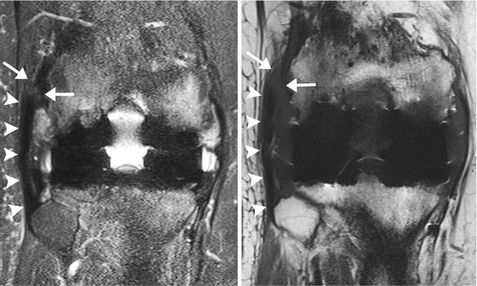

Fig. 32.9
MRI of a patient with instability after total knee replacement demonstrating a tear of the lateral collateral ligament
References
1.
Brown 3rd EC, Clarke HD, Scuderi GR. The painful total knee arthroplasty: diagnosis and management. Orthopedics. 2006;29(2):129–36; quiz 137–128.PubMed
2.
Dennis DA, Komistek RD, Kim RH, Sharma A. Gap balancing versus measured resection technique for total knee arthroplasty. Clin Orthop Relat Res. 2010;468(1):102–7.PubMedCentralCrossRefPubMed
Stay updated, free articles. Join our Telegram channel

Full access? Get Clinical Tree


