Fig. 4.1
A1, A2 3- and 6-noded triangular elements; B1, B2 4- and 8-noded isoparametric elements; C1, C2 8- and 20-noded isoparametric three-dimensional brick elements
On one hand, computations for two-dimensional problems are ended up with reduced integration approach (4-point Gaussian integration) or full integration approach (9-point Gaussian integration). On the other hand, computations for three-dimensional problems are analyzed by reduced integration approach (8-point Gaussian integration) or full integration approach (27-point Gaussian integration). Reference [11] is strongly recommended reading for details on finite element library.
For biomaterial or biomechanical applications, one may agree that Abaqus™ [12], Ansys® [13], MSC.Nastran® [14] and MSC.Marc® [15], are considered as a general purpose finite element code with most powerful element library. Major remarks for each of the four codes are given in Table 4.1.
Table 4.1
General purpose finite element codes for biomaterial or biomechanical applications
Code | Reference(s) | Major remarks |
|---|---|---|
Abaqus™ | Dynamic problems | |
Poroelastic element | ||
Ansys® | Joint contact problems | |
Crack element | ||
MSC.Nastran® | [25] | Linear problems |
Element for large deflection | ||
MSC.Marc® | Nonlinear problems | |
Element with full or reduced integration |
About Difficulties of an FEA for Biomaterials/Biomechanics
Actually, achievement of an FEA for biomaterials and biomechanics depends on its exact flow chart of modeling. In other words, it is to be introduced special terms depending on the simulation concepts [28], mesh quality [29], and patient-specific parameters [30]. Making a decision to obtain accurate prediction follows a highly acceptable flow chart of modeling including sometimes two-dimensional FEA [18, 19, 23] and sometimes three-dimensional FEA [20, 24, 31–33].
Moreover, there is a possibility to simplify the three-dimensional FEA using realistic interface boundary conditions. For example, a human lower jaw, one of the complex geometries in orthodontic mechanics, may be reduced to be a cube with respect to “an inclusion problem,” i.e., mini implant (see Figs. 4.2 and 4.3).
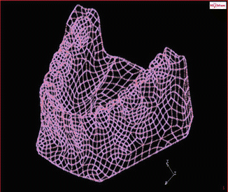
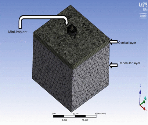

Fig. 4.2
Representation of a human lower jaw pre-model

Fig. 4.3
A simplified three-dimensional finite element model
As given below, one can list general difficulties for an FEA for biomaterial or biomechanical applications:
In biomechanical studies, sometimes, auto-meshing techniques give unacceptable results. To avoid the creation of undesired elements, suitable surface is to be created in the model.
It may be recollected that bias factor is a very good tool for using as the basis to generate a much finer mesh surrounding the critical area (inclusion, defect, crack, etc.). Singularity at the critical area can be easily reproduced by choosing the second-order isoparametric elements.
For the contact problems in biomedical engineering applications, FEA is to be covered by three steps: initial conditions, contact pair (edge in two-dimensional FEA, surface in three-dimensional FEA), and surface interaction.
According to Galerkin formulation, dynamically adaptive finite element grid method with dependent variables is to be considered. Details are given in [9].
Generally, numerical difficulty appeared while searching for a suitable refined mesh to give accurate result. For the sake of the geometry with its biomechanical nature, a number of elements are highly skewed or have large aspect ratios. Consequently, (1) the meshes are not considered suitable for accurate evaluation of stresses up to failure, and (2) due to the fact that force-displacement results are much less sensitive to mesh quality, computation of elastic behavior is considered suitable.
A Simple Example of FEA for Biomaterials
MSC.Marc® [34] is taken into consideration for the crack length prediction based on the work [35] of HV measurement with 200 g indentation load. For this purpose, a finite element model is introduced to predict J-integral field statically. It is claimed that the model proposed is very suitable for the prediction of fracture toughness of bioceramics with early indentation load. The model includes a quarter part of the indentation region as shown in Fig. 4.4. Acceptable fine mesh is defined to represent the critical part (i.e., crack) properly and to calculate reasonably correct J-integral values. Figure 4.5 indicates the fine-meshed model with 4-noded quadrilateral plane elements.
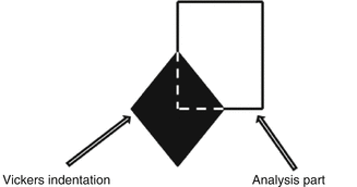
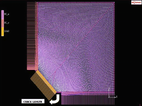

Fig. 4.4
Quarter part of the HV indentation region for the model

Fig. 4.5
Finite element model for the HV indentation region with general GML conditions
The fine-meshed model with 4-noded quadrilateral plane stress elements is analyzed by 10,000 elements without any bias factor. In this analysis of crack length prediction, full integration technique is preferred.
Under linear elastic [35, 36] plane stress and Palmqvist cracking-mode conditions [37], variations of E mean and SR of the finite element model proposed with respect to sintering temperature are given in Fig. 4.6.
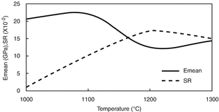

Fig. 4.6
Comparison of SR with E mean at different sintering temperatures
In the temperature range of 1100–1300 °C, it is noted from Fig. 4.6 that asymptotic curve of E mean decreases and then increases while increasing and falling curve of SR increases and then decreases respectively. Therefore, one can conclude that geometrical effect of the crack length prediction in the range of 1100–1300 °C is more clear than that of 1000 °C. In other words, crack length at 1000 °C is expected to be lower value than the others.
Finally, Fig. 4.7 shows that the variation of crack length prediction is similar to that of the HV. As expected, crack length at 1000 °C is lower than that of the other sintering temperatures.
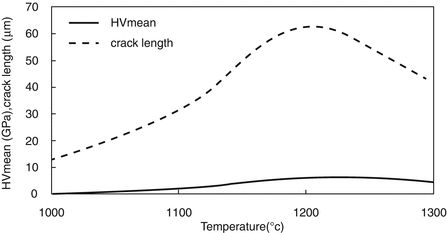

Fig. 4.7
Comparison of crack length with mean values of HV at different sintering temperatures
FEA with Clinical Significance
Based on appropriate physical examinations and complex GML conditions, biomechanical simulation and its FEA of an anatomic structure help the medical applications. As an example, in order to analyze a hip joint which is a very complex anatomic structure with different anatomic variations [38], a standard finite element-modeling methodology is to be developed to reach a clinically relevant knowledge (i.e., proper boundary condition and acceptable prediction) [39, 40]. When a model of the methodology is created for solving the difficult parts (such as the trabecular part [41]) of the hip, FEA will provide well-defended results for each subpart of the hip. Once the finite element model is validated and improved by using patient-specific data [42, 43], one can easily compare the differences between the model and the real hip to redesign the artificial hip (clinical trials) [44]. Moreover, the improvement limit of the finite element model is directly related to an anatomical subject-specific data [45].
For further clinical studies, this loop mentioned above is very important to estimate the risk range of the patient (from allowable to critical/fracture) in a correct manner. In other words, for the clinical applications with surgical techniques, FEA is a very useful tool to simulate stress distribution and to predict lifetime; in case of suitable model geometry, related material properties are considered [46–48].
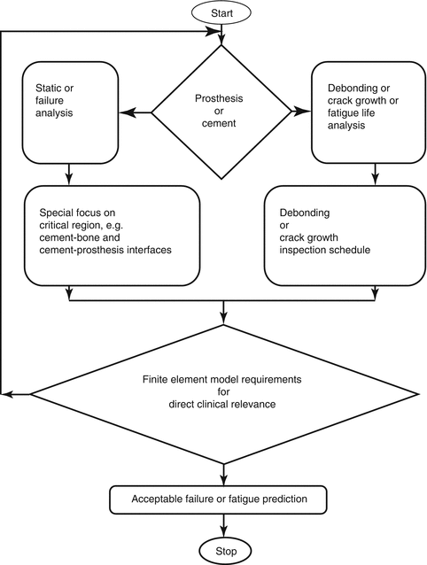
Shortly, one may assume that a human being is a function of sex, age, and living condition. Once this function is considered to create a finite element model, the model may be uncertain to provide clinically useful information. This type of model is called general model. When adding a parameter such as nutritional condition, the model may become certain and is called patient-specific model. That is, it is clearly advised that the analyst who creates the models is to consider the assumptions carefully. For another instance, prosthesis and cement relationship for a patient-specific study can be taken into consideration by defining the major loading conditions as shown in Fig. 4.8. It is obvious that Fig. 4.8 provides a flow diagram to understand whether (1) the FEA coincides with clinical experiences and (2) finite element model is improved for the patient-specific studies (reverse engineering).
 < div class='tao-gold-member'>


Only gold members can continue reading. Log In or Register to continue
Stay updated, free articles. Join our Telegram channel

Full access? Get Clinical Tree


