Radiographic Evaluation The surgeon should, in most cases, be able preoperatively to accurately determine the stability of the stem being removed, based upon established radiographic criteria for the assessment of cemented2 and cementless stem fixation.3 Well-fixed stems require interface access and division, using the techniques to be described. In addition, one should always identify the manufacturer and model of the existing stem. This can sometimes be accomplished radiographically. Nonetheless, prior operative notes and ideally, actual implant labels should be obtained to confirm identification. If the surgeon is not confident in his or her familiarity with a specific implant, a sample should be obtained from the manufacturer’s representative. This is particularly important for cementless stems and precoated or textured cemented stems. For these stems, one must identify the location and extent of the ingrowth surfaces or surface texturing, as these areas will have to be accessed in order to divide the bone-implant, bone-cement, or stem-cement interfaces. It is also important to realize that many stems, particularly those fabricated of titanium, are capable of supporting bone ongrowth in areas devoid of traditional ingrowth coatings. A sample stem should be examined for the presence of grit blasting or other texturing. Furthermore, one should determine whether the stem has an extraction hole or other geometric features that provide for the use of a stem-specific extraction device.
Prior to cemented stem removal, the cement mantle should be carefully assessed in terms of length and degree of canal filling. Gaps between the cement and endosteum can be exploited during cement removal. A lengthy segment of cement distal to the stem tip (Fig. 19-1) may require cortical windowing4 or an extended trochanteric osteotomy for removal. Areas of reentrant cement (cement under ledges of endosteal bone) should be noted (Fig. 19-2). The entire implant/cement construct must be examined in two planes and cortical perforations or extramedullary cement noted (Fig. 19-3).
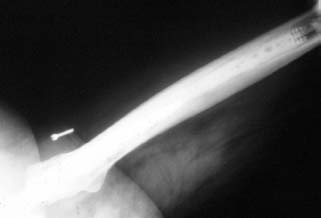
FIGURE 19-1. A cemented stem with a very long distal cement column.
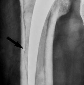
FIGURE 19-2. A loose cemented stem with reentrant cement (arrow).
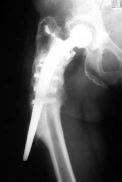
FIGURE 19-3. Lateral stem perforation surrounded by extruded cement.
One must formulate a plan not only for implant removal but also for the subsequent reconstruction. Femoral bone stock is assessed. In some cases where proximal bone stock is good, revision is possible with a standard-length stem despite the presence of a long distal cement mantle, which need not be completely removed. The details of revision component selection and templating are covered elsewhere in this text, but one caveat is appropriate. While the techniques for stem removal to be presented are generally effective and safe, fractures do occur, even in the most experienced hands. Therefore, implants appropriate for the management of perforations or periprosthetic fractures, including long stems, cables, plates, and bone graft, must be readily available.
Exposure Selection of the optimum surgical approach is based upon several factors, which are summarized in Table 19.2.
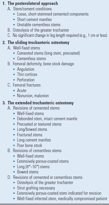
TABLE 19.2 Factors to be Considered in Selection of Surgical Approach
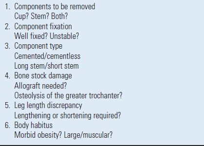
Many surgical approaches are suitable for femoral component removal. In selecting a particular surgical approach to facilitate implant removal, the subsequent method of reconstruction, including the choice of revision stem, must be considered. For example, if an extended trochanteric osteotomy is selected, a long, ingrowth revision stem is favored.5,6 Conversely, impaction grafting following an extended trochanteric osteotomy is associated with a high incidence of osteotomy nonunion.7 Other considerations include the degree and type of bone stock damage. If the femoral architecture is so distorted that a transfemoral corrective osteotomy is required, this can be performed early on to facilitate cement removal (Fig. 19-4). It is important to consider whether or not concomitant acetabular revision is needed, and if so, the exposure which that will require. Finally, the status of the greater trochanter should be carefully assessed. Standard trochanteric osteotomy in the presence of significant osteolysis poses the risks of nonunion or fragmentation of the trochanter during reattachment with cables or wires.8 Therefore, either a posterior approach or an extended trochanteric osteotomy that affords a larger surface for reattachment is preferred.
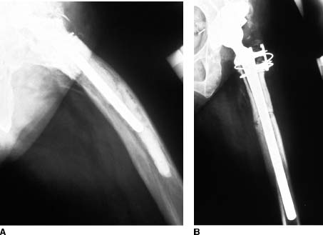
FIGURE 19-4. A failed cemented stem in a femur with a pronounced anterior bow. A: Preoperative lateral radiograph. B: Postoperative radiograph. A transfemoral osteotomy was performed to facilitate cement removal and to correct the angular deformity.
Favored exposures at the author’s center generally include the posterolateral approach, the sliding trochanteric osteotomy,9 and the extended trochanteric osteotomy.5,6 Indications for each are listed in Table 19.3. More extensile, combined anterior-posterior approaches are dictated by the need for complex acetabular revision.
Instrumentation Instrumentation specifically intended for the removal of cementless and cemented femoral components as well as cement are available from several manufacturers. The use of such dedicated equipment is strongly recommended. The temptation to improvise using general orthopaedic instruments increases the likelihood of complications such as fractures, perforations, prolonged operative time, and failure.
Instruments for Cementless Stem Removal The instruments required for cementless implant removal include a stem extractor, various tools for dividing the bone-implant interfaces, and a high-speed burr with metal cutting capabilities.
STEM EXTRACTORS. Extraction devices may be either stemspecific or “universal.” Among the stem-specific designs are those that engage a threaded hole in the prosthetic shoulder. These devices are generally effective. However, no extraction device should ever be used to forcefully extract a mechanically stable stem. Excessive force applied to a threaded extractor can strip the threads, particularly if the implant is titanium. Eccentric blows to the device can also break the threaded end of the extractor. Some stems have a transverse hole in the anterior-posterior direction through which a hook-shaped extractor is placed. Alternative designs are affixed to the neck or trunnion of the implant. If an implant-specific extraction device is not available from the manufacturer, various universal extractors, designed to work with any stem, are available1,10 (Fig. 19-5). It is recommended that one of these be readily available for all cases, in the event that the implant-specific device fails.
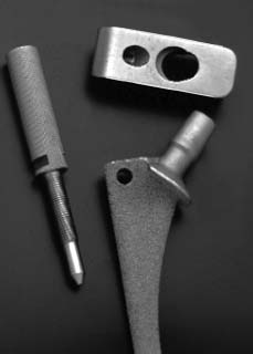
FIGURE 19-5. A universal stem extractor.
INSTRUMENTS FOR INTERFACE DIVISION-CEMENTLESS STEMS. Division of the bone-implant interface of mechanically stable cementless implants is performed with various instruments, depending upon the location of the ingrowth/ongrowth surface, and the surgical exposure employed. The required instruments are
- Flexible osteotomes in various lengths and configurations (Fig. 19-6)
- “Mini” power saw
- High-speed burr with a “pencil tip”
- Gigli saws
- Hollow trephines (Fig. 19-7)
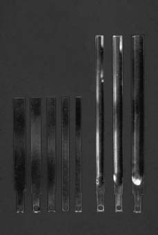
FIGURE 19-6. Flexible osteotomes designed specifically for division of the bone-implant interfaces of cementless stems are available in flat (left) and gutter (right) configurations.
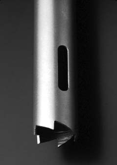
FIGURE 19-7. Hollow trephines are used to core out the distal portion of extensively porous-coated stems.
INSTRUMENTS FOR CUTTING METAL. The ability to cut metal is an essential element of the techniques to be described for the removal of certain porous-coated stems (as well as for the removal of some precoated or textured cemented stems). Tungsten-carbide bits on a high-speed drill (Fig. 19-8) are used to transect the stem or, on occasion, to remove a collar that impedes access to the proximal-medial interface.
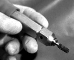
FIGURE 19-8. A tungsten carbide bit on a high-speed drill is essential for cutting metal and is also useful for debulking cement mantles.
Instruments for Cemented Stem and Cement Removal The removal of a cemented stem also requires an effective stem extraction device. These are essentially identical in design and function to those described for use with cementless stems. Other required tools include the following:
- Burrs to “debulk” the proximal cement mantle
- Power instruments to divide the implant-cement-bone interface of precoated or textured stems
- Hand instruments to fragment and remove the cement mantle
- Instruments to remove the distal cement column and cement restrictor
- Ancillary equipment
INSTRUMENTS TO “DEBULK” THE PROXIMAL CEMENT MANTLE. A high-speed burr is useful for removing the cement overlying the proximal lateral shoulder of a cemented stem. A tungsten-carbide burr designed for cutting metal is very effective for this application. Ultrasonic cement removal tools also can be used.11,12
INSTRUMENTS FOR DIVIDING THE IMPLANT-CEMENT INTERFACE. Both hand and power instruments are useful for cemented stem interface division. If the stem can be removed from the cement mantle, hand instruments are preferred for fragmenting the cement and separating it from the endosteum (Fig. 19-9). If the stem cannot be removed, the interfaces are disrupted with thin, high-speed burrs.
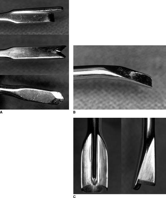
FIGURE 19-9. Hand cement removal instruments. A: Cement splitters are available in a variety of different configurations. B: A cement elevator is used to separate the cement from bone. C: A combination elevator-splitter.
INSTRUMENTS FOR REMOVING THE DISTAL CEMENT COLUMN AND CEMENT RESTRICTOR. Several instruments are available for removing the cement distal to the stem tip as well as the cement restrictor. Long drills with corresponding taps (Fig. 19-10), segmental cement extraction systems, and ultrasonic cement plug pullers are examples.11–14
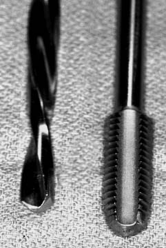
FIGURE 19-10. A drill and corresponding tap.
ANCILLARY INSTRUMENTS. During cement removal, good visualization of the intramedullary canal is mandatory. A hand-held or head-mounted fiber optic light source is recommended. Conventional suction tips are easily clogged by cement and soft tissue debris. A specially designed suction tip with an integral debris trap is very useful in overcoming this problem. Combination devices that incorporate fiber optic illumination, suction, and irrigation in the same handle are now available (Fig. 19-11).
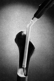
FIGURE 19-11. Combination suction-irrigation and fiber optic light source hand piece.
Grasping devices for retrieving cement fragments should be available in various lengths and configurations. These generally resemble pituitary rongeurs (Fig. 19-12). Designs with the grasping end slightly offset in relationship to the handle and shaft improve visualization in the depths of the femoral canal.
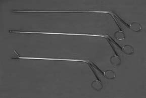
FIGURE 19-12. Specially designed cement graspers for use in the femoral canal.
TECHNIQUES FOR THE REMOVAL OF CEMENTLESS FEMORAL COMPONENTS
The removal of an unstable stem can be accomplished with simple manual extraction without the necessity for trochanteric osteotomy. In order to avoid fracture, one must be careful that no trochanteric overhang obstructs the pathway of stem exit.
The remaining discussion is devoted to mechanically stable implants. Regardless of the preoperative radiographic prediction of implant fixation, mechanically stable implants are defined intraoperatively by their failure to move after several firm (but not violent) blows applied to an extraction device secured to the implant. When this is the case, further attempts at forceful manual extraction must be abandoned and efforts directed toward access and division of the bone-implant interface. The approach to this task varies according to the extent of the ingrowth surface, and for extensively coated stems, according to the mode of fixation (bone ingrowth/ongrowth vs. stable bone–fibrous tissue encapsulation) and the degree of femoral canal filling.
Proximally Coated Stems For well-fixed proximally porous-coated stems, either a sliding trochanteric osteotomy or a short extended trochanteric osteotomy is recommended. The interface requiring division is situated in the metaphysis and therefore largely in cancellous bone. Though this bone may be densified, one can usually pass a thin flexible osteotome in the interval between the cortex and the implant. This requires constant attention to the direction taken by the osteotomes, as they are quite sharp and may veer off of the implant surface to exit the surrounding bone. The flat osteotomes are passed from proximal to distal about the femoral neck and from lateral to medial through the trochanteric osteotomy (Fig. 19-13). Crescentic or “gutter” osteotomes are passed from proximal to distal along the lateral aspect of the implant to divide the interface in this area (Fig. 19-14). Alternatively, a “mini” oscillating saw may be passed from lateral to medial through the trochanteric osteotomy to divide the anterior and posterior interfaces in a fashion analogous to that described for the flat osteotomes (Fig. 19-15). Finally, one may employ extra-thin cutting tools on a high-speed motor, specially designed for division of the bone-implant interface. These tools are preferable to osteotomes in areas where the stem is in direct contact with cortical bone. One often encounters areas of dense endosteal hypertrophy3 at the termination of an ingrowth surface (Fig. 19-16). It is best to disrupt these interfaces with a high-speed burr.
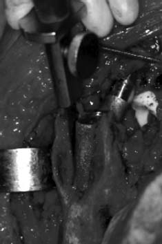
FIGURE 19-13. A flat flexible osteotome is used to divide the proximal bone-implant interface anteriorly and posteriorly, with the access provided by a sliding trochanteric osteotomy.
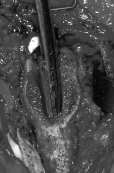
FIGURE 19-14. The lateral bone-implant interface is divided with a gutter shaped osteotome.
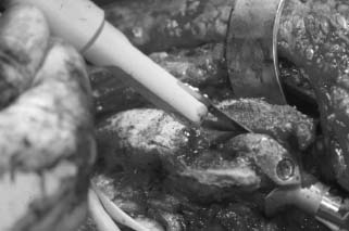
FIGURE 19-15. A “mini” oscillating saw can also be used to divide the proximal bone-implant interfaces anteriorly and posteriorly.
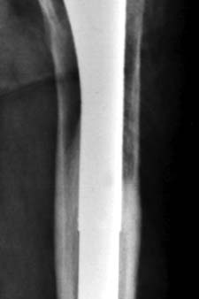
FIGURE 19-16. Radiograph of a bone-ingrown 5/8ths porous-coated stem. Note the endosteal hypertrophy at the distal aspect of the porous coating.
While the anterior, posterior, and lateral bone-implant interfaces are accessible through the trochanteric osteotomy, the proximal-medial interface is not. For collarless implants, this interface is accessed from proximal to distal through the femoral neck. Direct contact between the implant and cortical bone is common in this area, and the high-speed cutting tools are generally used. The presence of a collar will obscure access to this area. The most direct solution is to remove the collar with a tungsten carbide cutting tool on a high-speed motor, and then proceed with interface division as described for collarless implants. This is quickly accomplished for implants fabricated of titanium alloy, which is easily cut. Removing the collar of a cobalt chromium stem is much more difficult and time consuming. Several cutting bits are usually required, and it is therefore expensive. This has prompted some surgeons to recommend an alternative method using a Gigli saw.6 The saw is passed around the medial aspect of the prosthetic neck below the collar. The two limbs of the saw are brought out laterally, parallel to the anterior and posterior implant surfaces, to exit through the trochanteric osteotomy. The handles are alternated back and forth and simultaneously drawn distally (Fig. 19-17). A short extended trochanteric osteotomy is therefore recommended in conjunction with this technique. Once all areas of the bone-implant interface have been divided, implant removal is usually easily achieved with an appropriate extraction device. Several precautions are offered. As is true during the initial assessment of mechanical implant stability, if several firm blows to the extraction device fail to produce any implant movement, attempts at removal are stopped—the implant is still stable, most likely because the interface has not been adequately divided. All interfaces should then be revisited with the techniques described above. Rarely, proximally coated implants will remain stable even after complete division of the interface between the primary ingrowth surface and the bone. In the author’s experience, this has occurred only with titanium stems and then only when the distal stem was grit blasted or corundumized. These stems were eventually removed utilizing the techniques to be described for extensively porous-coated stems. Subsequent histological examination confirmed osseointegration, despite the absence of a true porous surface. This information must be born in mind when contemplating the removal of a “proximally” coated titanium stem, especially if it is known to be grit blasted or otherwise roughened distally, is canal filling, and shows radiographic signs of osseointegration such as endosteal hypertrophy and lack of reactive lines adjacent to the distal portion of the stem.
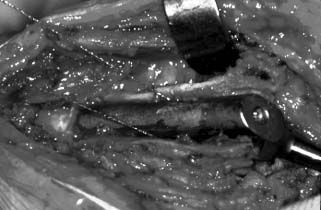
FIGURE 19-17. A Gigli saw is used to divide the proximal-medial bone implant interface.
Extensively Coated Stems Stable extensively porous-coated femoral components are sometimes erroneously regarded as being “distally fixed.” While adaptive remodeling about such implants may result in the most abundant ingrowth at the distal limit of the coating, such stems are in reality “extensively fixed.” Proximal interface access and division are therefore equally as critical to the removal of these stems as they are for proximally coated stems and are accomplished in exactly the same fashion. In addition, distal interface access and division are required. The techniques for accomplishing this are dependent upon the nature of the ingrowth (bone-ingrowth vs. stable bone–fibrous tissue encapsulation), and the degree of diaphyseal canal filling by the stem. Stable bone–fibrous tissue encapsulated interfaces are characterized by a neocortex separated from the ingrowth surface by 1 to 2 mm. Radiographically this appears as a reactive line, which parallels the implant surface (Fig. 19-18). For undersized extensively coated stems fixed by stable bone–fibrous tissue encapsulation, the neocortex is joined to the endosteum by less dense trabecular bone. In such cases, osteotomes passed along the length of the implant can be effectively used to divide these trabeculae outside of the neocortex. Occasionally, significantly undersized extensively porous-coated stems become fixed by bone ingrowth (Fig. 19-19). The trabeculae joining the endosteum to the surface of such stems can also be divided with osteotomes in areas where the implant is widely separated from the cortex. If the stem is well centered within the femoral canal, the entire interface can be divided in this fashion. If, however, the stem is in significant varus or valgus and there is direct contact between the stem and the endosteum, osteotomes are not recommended, and these are treated as bone-ingrown canal-filling stems. The same is true for canal-filling stems with stable fibrous fixation.
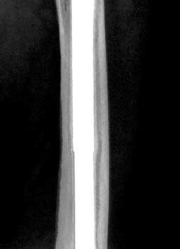
FIGURE 19-18. A cementless stem demonstrating stable fibrous fixation as evidenced by reactive lines that parallel the porous-coated ingrowth surface.
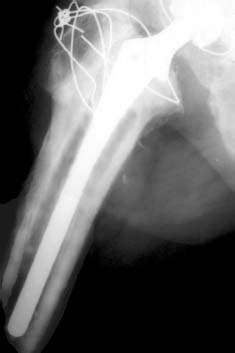
FIGURE 19-19. An undersized, extensively porous-coated stem fixed by bone ingrowth.
Extensively porous-coated, canal-filling, bone-ingrown stems present the greatest difficulties for removal. The use of osteotomes, however thin, poses a high risk of fracture and is to be avoided. Because no space is present between the stem and the cortical bone, access and division of the bone-implant interface require the use of an instrument capable of removing interface material as the instrument is advanced distally. Our preference in such cases is the so-called trephine technique, which can be performed in two different ways. The original technique1 was developed for use in conjunction with a sliding trochanteric osteotomy (Fig. 19-20). Following proximal interface division, the anterior femoral cortex is exposed. The junction between the proximal triangular and distal cylindrical segments of the implant is located using an appropriately sized trial placed over the anterior femur. This location is marked, and an oval window is created in the anterior femoral cortex with a burr, beginning at the mark and extending distally for approximately 1 cm. The window should be approximately 1.5 cm in width from medial to lateral. Next, the stem is transected, using a tungsten carbide cutting tool on a high-speed motor passed through the window. The surrounding soft tissue is isolated from the cortical window, using plastic drapes or moistened towels in order to avoid metal contamination. Copious irrigation is required to speed cutting, to prevent rapid dulling of the cutting tool, and to minimize thermal necrosis of the surrounding bone. Several cutting bits may be required. The volume of metal that must be removed increases with the square of the stem diameter. Hence, the transection of a 15.0-mm stem takes more than twice as long as a 10.5-mm stem (and twice the number of tungsten carbide bits). After the stem is transected, assuming that proximal interface division has been complete, the proximal segment of the implant can be removed with an appropriate extraction device. The remaining distal segment of the stem is then “cored out” utilizing the smallest available trephine that will fit over it. Copious irrigation is required. In addition, the trephine should be periodically removed from the femoral canal and the canal thoroughly flushed of debris before the trephine is advanced further. More than one trephine may be required, depending upon the length of the stem. When interface division is complete, the distal segment of the stem will “seize” within the trephine, which is then withdrawn.
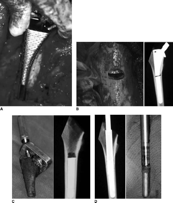
FIGURE 19-20. Steps in the removal of a bone-ingrown, extensively porous-coated stem with a sliding trochanteric osteotomy. A: Localization of the junction between the proximal metaphyseal portion of the stem and the distal cylindrical portion using an appropriately sized broach-trial. B: The anterior cortex is windowed over the junctional area and the stem is transected with a tungsten carbide burr. C: After proximal interface division, the upper portion of the stem is removed. D: An appropriately sized trephine is used to core out the distal segment of the stem.
Younger et al.6 have described a modified version of this technique for use in conjunction with an extended trochanteric osteotomy (Fig. 19-21). The osteotomy is carried distally approximately 2 cm beyond the junction of the proximal metaphyseal and distal cylindrical portions of the stem. Proximal interface division is performed as above, using osteotomes or a small oscillating saw anteriorly and posteriorly and a Gigli saw medially. The stem is then transected through the osteotomy rather than through an anterior cortical window. The trephine is used distally in identical fashion as above.
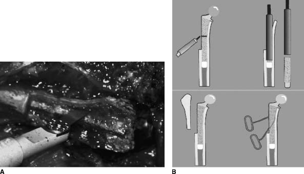
FIGURE 19-21. A: Extensively porous-coated stem removal using the extended trochanteric osteotomy. B: The exposure allows stem transection and trephining of the distal stem through the osteotomy.
Curved-stem extensively porous-coated prostheses are approached in a similar fashion. However, the extended trochanteric osteotomy must extend distally at least to the apex of the bow in the prosthesis. The stem is transected as above, and the proximal segment is removed. The trephine is driven distally but will bind on the stem when it reaches the prosthetic bow. When this depth is attained, the stem is transected a second time at the apex of the bow. The remaining stem beyond the curve is removed with a trephine.
A special situation exists when managing a patient with a late hematogenous infection of a bone-ingrown, extensively porous-coated stem associated with septicemia. Such patients are usually quite ill and poorly suited to tolerate a lengthy surgical procedure. After medical stabilization, implant removal should be accomplished as expeditiously as possible. In these cases, it is recommended that an extended trochanteric osteotomy be carried along the entire length of the prosthesis. The stem is not transected. Instead, the anterior and posterior interfaces are divided along the full length of the stem with a small oscillating saw. The entire medial interface is divided with a Gigli saw.
TECHNIQUES FOR THE REMOVAL OF CEMENTED FEMORAL COMPONENTS
Component and Cement Removal Without an Extended Osteotomy Conditions may be such (see Table 19.3) that stem and cement removal can be accomplished either without any trochanteric osteotomy or with a short standard or sliding osteotomy. In general, this assumes that the stem can be extracted from the cement mantle and the bone-cement interface can be accessed from proximal to distal through the femoral neck or trochanteric osteotomy site. This is possible if the stem is unstable within the cement mantle (Fig. 19-22). If the stem is stable within the cement mantle, extraction is possible only if the stem has a smooth surface and does not have a complex geometry that allows reentrant cement to mechanically lock it in place.
TABLE 19.3 Indications for Various Surgical Approaches
Related posts:

Stay updated, free articles. Join our Telegram channel

Full access? Get Clinical Tree


