Chapter 118 Electromagnetic Computer-Assisted Navigation
Since the first uses of navigation appeared in orthopedics in the late 1990s, much has changed in terms of application, expectations, and options.* More information that has become available on failure allows the surgeon to refine accuracy in avoiding mechanical misalignment and in using individual components to reduce shear and eccentric loading.5–711 Computer-assisted navigation (CAS) is one tool that now is more available, user-friendly, and versatile, and increasingly less expensive.
Because of problems involving fixation, signal acquisition, and signal disruption by operating room (OR) personnel, thought was given to a non–line-of-sight signal that would be powerful enough to penetrate soft tissue, yet would not be prone to radiation such as that found in x-rays or fluoroscopy.8 Electromagnetic (EM) CAS provided this full-radius reception without radiation exposure. EM CAS was first used for neurosurgical and ear, nose, and throat (ENT) applications in pediatric cranial surgery, where 360-degree coordinate measurements and minute three-axis navigation are necessary.20
Physics Behind Electromagnetic Navigation
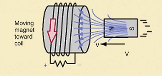
By creating a low-intensity magnetic field, copper coil sensor receivers (DRFs) are able to read the strength received from the electromagnetic field and produce a microcurrent. This field is produced by a transmitter or localizer that runs off of AC or DC current. Usually, these localizers are made by combining three or more coils that produce magnetic strength in an intermittent fashion, so as to constantly produce an oscillating or varied field, which imparts stronger sensitivity for receiver reception. The magnetic field is generally one gauss (0.0001 Tesla). A DRF placed in a particular position away from a magnetic field will transmit varied electric current depending on its position in relationship to field strength. However, the electric current produced is based on changes in the magnetic field, as well as in its intensity, hence the rationale behind a pulsed or oscillating field. The coil positioned in a parallel direction in relation to the field produces the maximum strength, whereas 90-degree polarization negates the electric current produced. With knowledge of field strength, computer calculations can determine its direction (Fig. 118-1). The system then can locate and orient the position of the receiver by the electric current it receives from one or more coils. A coil may measure not only field strength, but also the direction of the magnetic field, such that the XYZ position can be determined. It can also compute pitch and yaw, which is better known as 5 degrees of freedom. However, the sixth degree or role cannot be determined without two or more receiver coils to obtain this final dimension of orientation. Therefore, DRFs in an orthopedic setting will always have two coils. If an additional coil is used, it can fine-tune or can be a reference for the two primary coils to improve accuracy.
Transmitter coils, or field strength generators, are merely solenoids that are powered through the use of AC or DC current. Both types of technology have inherent advantages and disadvantages. Although DC is simple, it is not as accurate as AC because the sample size of the signal is reduced. Also, the magnet necessary to power the system is somewhat obtrusive in an operative field. AC technology uses audiofrequency wave energy to transmit to the receiver coil. The receiver coil works in much the same way as a transformer, in that it consists of loops of wire that create a small electric current. Through this oscillation system, a time sequence for frequency-multiplexed transmission of multiple magnets can create a more consistent and sustaining magnetic field that is less susceptible to outside interferences, such as metal, or environmental factors of other electromagnetic sources. It also is more prone to be misread by DRFs; therefore outside interferences are capable of disrupting accuracy. In the AC system using three-coil technology, computation is significantly more complex in terms of mathematical determination of the positions of instruments because of the oscillation, creating a more robust network of signals from the higher number of measured signal transmissions per second.15 Yet as a result of increased signal sampling, the CAS system has enhanced sensitivity. Additionally, the magnet necessary to power the system is somewhat obtrusive in an operative field. Multiple coils can reduce the size of the transmitter but can increase the computation time and the speed of localization. As such, AC technology is currently the gold standard.
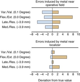
Originally, it was believed that DC current systems would offer the advantage of less interference from metal and other conductive distortions. However, in practice, the effect is a creation of fields from remote metal sources, which actually distort the navigation more than in a pulsed AC system. Because of these issues, AC technology has been adopted as the standard (Fig. 118-2).
Part of the exceptional accuracy of the systems stems from the aforementioned transmitter field generation system. However, additional precision has been achieved by smart instruments, which have defined read only memory (ROM) values. When the computer recognizes a particular distinctive discrete sensor that has its own ROM chip, the device, when powered up, can be individually calibrated to the highest level of accuracy without the need for user interaction. Although single-coil navigation is possible, incorporation of a second or third coil makes accuracy and precision of the system even better defined. Despite these measures to enhance accuracy, it is important to realize that the bench-tested accuracy of any system is only as good as the environment in which it is used. Soft tissue shifts, environmental factors of metal or magnetic distortion, and surgical tactile accuracy all play a large role in the intraoperative accuracy of any system.16
Sources of Distortion
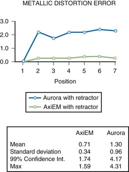
Ferrous interference is the more frequently referenced and better understood concept, especially given our understanding of magnetic resonance imaging (MRI) interferences. Any object to which a simple magnet is attracted can be considered ferrous. Generally, the stronger the attraction, the more ferrous is the metal. Therefore, steels such as the 400 Series and 17-4 stainless are highly ferrous. Because aluminum and titanium cobalt chrome are not as ferrous, they tend not to “bend” the magnetic field and therefore create less distortion. The effects of ferrous metals are seen in both AC and DC systems. However, AC CAS is least affected by remote ferrous interference (Fig. 118-3).
Cons of EM
Other signal disrupters include some metals that may interfere with reception strength. Examples are aluminum, copper, and stainless steel (see Fig. 118-3). Yet some metals, such as the 300-series stainless (303, 316 L), cobalt chrome, and all of the titanium alloys, have a surprisingly low interference constant.
Related posts:
 Cemented Total Knee Arthroplasty: The Gold Standard
 Management of Extra-articular Deformity in Total Knee Arthroplasty With Navigation
 Patellar Instability
 Distal Realignment of the Patellofemoral Joint: Indications, Effects, Results, and Recommendations
 Anterior Cruciate Ligament Reconstruction With Central Quadriceps Free Tendon Graft
 Osteochondritis Dissecans
Stay updated, free articles. Join our Telegram channel

Full access? Get Clinical Tree


