I. Overview
A. Anatomy—For functional and anatomic reasons, the cervical spine can be divided into anatomic regions: the upper cervical spine (UCS) and the lower cervical spine (LCS).
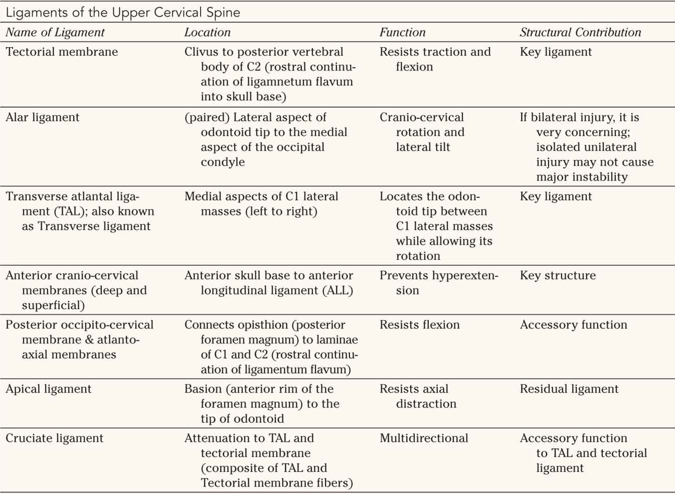
1. Upper cervical spine—The UCS (Fig. 27-1) extends from the skull base to the lower endplate of C2. It includes the occipital condyles and the bony aperture surrounding the foramen magnum, the C1 segment (atlas) and the C2 segment (axis). Conceptually, the C1 segment functions as a “washer” between the skull base and the C2 segment. The axis consists of the odontoid with its tip resting between the lateral masses of the atlas and its narrow waste. The superior articular processes of the atlas are convex and rest below the concave inferior facets of the atlas. They are connected through a bone bridge (pars interarticularis) on either side to the inferior articular processes. With its unique anatomic configuration, the UCS allows for extensive motion between its contributing segments and provides minimal intrinsic stability between the skull base and the LCS. Anatomic alignment of the bony segments of the UCS is maintained by several important ligamentous structures (Table 27-1; see Fig. 26-1). Occipito-cervical stability is provided by a few key ligaments, which are listed in Table 27-1 and are depicted in their functional arrangement in Figure 26-1. These ligaments allow for approximately half of the C-spine motion in rotation and flexion/extension while protecting the spinal cord and vertebral arteries. It is important to remember that these ligaments together form the functional unit of the UCS, with any bony or ligament injury to this area representing a more serious injury.
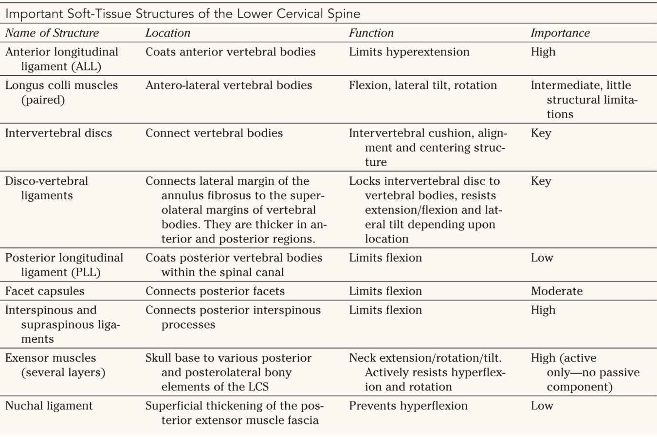
2. Lower cervical spine—The LCS begins with the caudal half of the C2 vertebral body and ends with the Tl segment. Similar to the upper C-spine, the lower C-spine requires functional integrity of its soft-tissue components (Table 27-2) to maintain a balanced alignment and to protect neurological elements. A healthy C-spine has a lordotic alignment of approximately 20° between the inferior vertebral body of C2 and the inferior C7 vertebral body. This assures balanced distribution of loads between vertebral bodies and lateral masses (tripod concept). The uncovertebral processes are unique to the cervical spine. They arise out of the lateral margins of the superior aspects of the vertebral bodies and secure the spinal column against excessive lateral tilt. Well-functioning extensor muscles are necessary to provide active neck control and maintain balance. All together, the anatomic arrangements of the LCS allow for considerable motion while maintaining usually less than 11° flexion/extension and less than 3.5-mm translational motion between each adjacent segment.
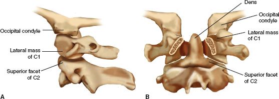
FIGURE 27-1 Osseous anatomy of the upper cervical spine. Note the functional unit that is formed by the occipital condyles and C2; C1 serves as an “intercalary washer.” The bony elements offer no inherent stability toward one another. A. Important articulations as seen on a lateral projection plane. B. Posterior to anterior cutaway view with the posterior elements of C1 and C2 removed through the pedicles.


B. Incidence and Injury Mechanism—The neck and its surrounding softtissue structures are more prone to injury than the lower thoracolumbar spine due its exposed location, permissiveness to an extensive range of motion, relatively small size, and proportionally frail ligamentous restraint structures. The relatively large mass of the head tethered to the rostral cervical spinal column exposes the cervical spine to injury due to indirect mechanisms. Important determinants of the type and magnitude of injury sustained are the position of the head at the time of impact and the direction and magnitude of the kinetic energy acting on the C-spine. A large number of variables contribute to the severity of the injury, including the age of the patient, bone mineral health, pre-existent ligamentous laxity, spinal ankylosis, and spinal canal size. In general, flexion and bursting type injuries affect the LCS most commonly in a younger more active age group due to deceleration trauma, while elderly patients are more commonly affected by hyperextension injuries commonly sustained from ground level falls. Direct trauma to the cervical spine usually results from penetrating injuries, especially in North American urban regions. The spectrum of C-spine injuries ranges from mild soft-tissue sprains to life-threatening high-grade fracture dislocations. Some 2% to 5% of patients with blunt trauma can be expected to have sustained a fracture or dislocation of the cervical spine. Increasingly elderly and frail patients with concomitant degenerative C-spine disorders and multiple comorbidities suffer from serious C-spine injuries, which can be easily missed and for which there commonly are no simple treatment options.


II. Evaluation
A. Overview—Systematic clinical evaluation forms the basis of C-spine injury evaluation. The NEXT criteria identify that a patient who (a) is cognitively unimpaired, (b) has not sustained a high kinetic injury mechanism (i.e., motorized vehicle crash >35 mph, fall >4 ft, presence of acute cranio-cervical fractures, long-bone or pelvic fracture), (3) has a nonfocal neurologic examination and nonpainful full neck range of motion does not require radiographic assessment. Although these criteria have been shown to be highly predictive of absence of neck trauma, they rarely apply in a trauma setting.
The basic principle in the evaluation of a trauma patient is to assume the presence of an unstable spinal injury and then to rule it out based on clinical evaluation and imaging studies. As in all trauma patients, spine precautions, including C-spine immobilization, are maintained during resuscitation and evaluation until a determination of spine stability has been made.
B. Clinical Evaluation—Clinical evaluation starts with the history of injury mechanism (if available) and review of basic vital signs. After successful resuscitation using the advanced trauma life support ABC principles, a more comprehensive patient evaluation, including assessment for spinal injuries, is performed. Inspection and palpation of a traumatized patient’s spine are performed from occiput to sacrum using a logroll maneuver. Any manipulation of the neck is avoided outside life-saving efforts. Particular attention is directed to areas of bruising, focal tenderness, or interspinous gaps along the posterior midline. In conscious and cooperative patients, a formal examination includes assessment of the Glasgow Coma Scale (see Table 1-1), cranial nerve function, and evaluation of extremity motor, sensory, and reflex function. Testing of these functions is performed according to the guidelines of the American Spinal Injury Association (ASIA) (see Fig. 25-4). In unconscious sedated patients, segmental motor and sensory testing should be attempted, but is commonly limited. Withdrawal responses and the presence of deep tendon reflexes and long tract signs are important components in the evaluation. Assessment for priapism in males, detailed rectal examination, and assessment of the bulbocavernosis reflex should be performed in patients with suspected spinal cord injury and in unconscious patients.
C. Radiographic Evaluation (Fig. 27-2 and Table 27-3)
1. Plain radiographs—Radiographic evaluation of the cervical spine is suggested in patients with neck pain after a significant injury mechanism, in the presence of facial fractures, polytrauma, neurologic deficits, or symptoms, and in patients with altered mental status and a history of possible significant trauma. The plain lateral C-spine radiograph remains the most important imaging test for identifying fractures and dislocations of the neck and ideally visualizes the skull base to the C7–Tl motion segment. Due to common limitations of visualizing the cervico-thoracic junction, swimmer’s views or shoulder pull-down views are necessary to assess the cervicothoracic junction on a lateral radiograph. Open-mouth odontoid views are used to assess the odontoid and the Cl lateral masses. An anteroposterior (AP) C-spine radiograph usually allows for assessment of the C3 segment to the UCS. Trauma oblique radiographs can be helpful in visualizing the neuro-foramina and the facet joints of the LCS.
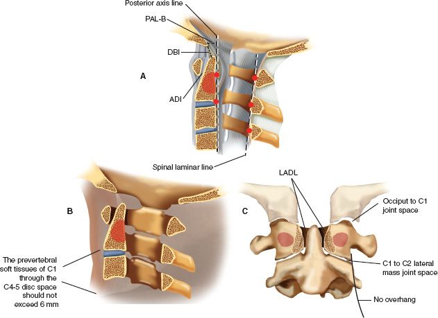
FIGURE 27-2 Accurate interpretation of the landmarks of the upper cervical spine is important for injury assessment in this region. A. On the lateral radiographic image the most posterior cortical margin of the bony spinal canal of C1, C2, and C3 should form a line (spinal laminar line) of which no point deviates more than 1 mm. The anterior cortex of the odontoid should lie in close proximity (and parallel) to the posterior cortex of the anterior arch of C1; this distance of atlas to dens is referred to as the ADI and should measure less than 3 mm in a normal adult and less than 5 mm in a normal child. The ADI is maintained primarily by the transverse atlantal ligament. Two important reference lines for the physiologic craniocervical articulation are the dens-basion interval (DBI), which should be less than 12 mm, and the distance of the basion to the posterior axis line (PAL-B), which should not exceed 12 mm, with the basion not protruding posteriorly beyond 4 mm. B. The prevertebral soft tissues of C1 through the C4 to C5 disc space should not exceed 6 mm of thickness (as seen on the lateral radiograph) in normal individuals. Artifacts may be caused by endotracheal or esophageal tubes and crying. C. On an open-mouth odontoid or coronal CT reformatted view the C1 lateral masses should not overhang C2. In addition, the occiput to C1 and the C1 to C2 joint spaces should be nearly uniformly equidistant (occiput to C1 joint space, 1 to 2 mm; C1 to C2 lateral mass joint space, 2 to 3 mm). The odontoid should be centered symmetrically between the C1 lateral masses. (The lateral atlas-dens interval [LADI] should not vary by more than 2 mm.)


Due to their time- and resource-intensive nature, such plain radiographs have increasingly been replaced by helical CT-scan with coronal and sagittal reformatted views with comprehensive visualization of the entire C-spine from the skull base to the upper thoracic spine.
Among many subtle findings, a normal lateral cervical spine radiograph is expected to demonstrate maintenance of physiologic lordosis, absence of vertebral subluxation or kyphosis, symmetrically maintained disc heights, congruous, overlapping facet joints without subluxation, and a narrow prevertebral soft-tissue shadow. Although plain cervical radiographs are still used today, they are rapidly being surpassed by helical CT scans with reformats as a faster and more sensitive modality.
2. Lateral flexion-extension radiographs—Lateral flexion-extension radiographs remain a controversial but efficient way for assessing cervical spine stability. In awake, fully cooperative patients who are neurologically intact and have normal plain radiographs, X-ray studies taken with maximum pain-free neck extension and flexion may provide helpful early determination of spinal stability. In patients who do not meet these prerequisites and have continued neck pain, delayed reevaluation with a second clinical and radiographic examination using flexion and extension radiographs on a delayed nonacute basis is mandated.
3. Computed tomography (CT)—Noncontrast CTs of the neck have largely surpassed plain radiographs as the imaging modality of choice in assessing and diagnosing cervical spine injuries. Helical CT scans with sagittal and coronal reformats can be rapidly obtained and are more sensitive than plain radiography. Noncontrast head CT scans have become the common initial screening study for patients presenting with cognitive impairment. Adding a cervical spine screening from the skull base to T4 is time- and cost-effective. It is also considered more sensitive and cost-effective than plain radiography, however, at higher radiation exposure. In an obtunded patient, a CT scan without any abnormality can also be used to clear the cervical spine without the addition of controlled flexion-extension radiographs or the addition of MRI.
4. Magnetic resonance imaging (MRI)—MRI is recommended for patients with spinal cord injury, especially in the presence of progressive or unexplained neurologic deficits or discrepant skeletal and neurologic injury. Controversy persists as to the timing of an MR scan relative to reduction attempts in a displaced spinal column injury. It is widely accepted to proceed with a closed reduction of a dislocated spinal column using sequential cranial traction in an awake patient before performing MRI; this approach is intended to minimize the duration of ongoing spinal cord compression and optimize chances for cord regeneration. If readily available, an MRI scan can be considered in neurologically intact patients or in the presence of an unknown neurological status before reduction to rule out the presence of a large disc herniation, which may cause postreduction spinal cord compression. MRI can also detect posterior interspinous ligament and facet capsule injury, especially within the first 72 hours, and can allow differentiation of full-thickness tears and sprain. The additional cost and imaging time poses a limitation to this modality on a routine screening basis. MRI scans in the pediatric population are limited by lack of compliance issues. Usually monitored sedation or preferably general endotracheal intubation are required for a quality study. This should be duly considered prior to ordering a MRI in these patients. MRI may not be useful in the morbidly obese patient (who cannot fit into the MRI gantry), patients with significant fixed deformities due to inflammatory spinal conditions, and patients with pacemakers or implantable stimulators.
5. Bone scans—Bone scans are rarely used in the assessment of acute cervical spine trauma. They have a limited role in the evaluation of occult spine fractures, especially in skeletally immature patients. Typically, this modality is not useful until at least 48 hours after injury; further enhancement with single photon emission CT (SPECT) may be necessary to increase image resolution of the small bony structures of the cervical spine. With the advent of current technology and imaging resolution with CT and MRI imaging, bone scans are essentially obsolete in traumatic conditions.
6. Other tests—Noninvasive vascular tests can be of value in the assessment of vertebral artery injuries. CT angiography (CT-A) is recommended with fractures into the transverse foramina or in patients with significant posttraumatic malalignment or displacement as in the case of facet dislocation. CT angiography has largely displaced invasive arteriography as a screening tool. Transcranial Doppler tests and MR angiography are usually secondary-tier tests for patients with unclear CT-A or in the presence of unexplained mental status changes. Although the sensitivity of these tests is high, the specificity remains well below that of arteriography. Routine use of noninvasive vascular tests and treatment of suspected vertebral artery injuries remain in a state of evolution.
III. Injury Classifications—Injury classifications of the spine attempt to predict spinal stability by describing neurologic injury, bony injury, and disruption of disco-ligamentous structures. There are descriptive systems, which identify the injured anatomic components of the injured segment. Finally, there are systems that ascribe an injury mechanism to the imaging tests. Spinal cord injury classifications are described in Chapter 25. In the upper C-spine, there are level-specific well-established classifications. Unfortunately, there is no such consensus for the lower C-spine. Many variations of descriptive anatomic and mechanistic models continue to persist, thus impeding, among other things, study, and testing.
A. UCS Injuries
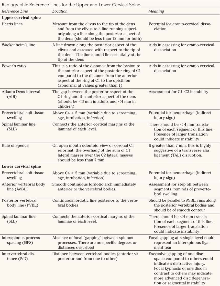
1. Occipital condyle fractures (Fig. 27-3) The major classification scheme used to differentiate occipital condyle fractures is that of Anderson and Montesano described in 1988.
• Type 1—Impaction mechanism: comminution of the occipital condyle with an impaction mechanism; these fractures are stable and are managed conservatively.
FIGURE 27-3 Occipital condyle fractures. The alar ligaments provide important structural support for the craniocervical junction. Type I injuries are relatively stable and demonstrate comminution of the occipital condyle. Type II injuries are basilar skull fractures extending into the occipital condyle; they are relatively stable. Type III injuries are potentially unstable avulsion injuries of the alar ligament with the tip of the occipital condyle.
• Type II—Shear mechanism: basilar skull fracture with occipital condyle involvement; these fractures are stable and are usually managed in accordance with the basilar skull fracture.
• Type III—Distraction: avulsion of the alar ligament with the tip of the occipital condyle; these fractures may be unstable and an associated craniocervical dissocation (CCD) or atlantooccipital dissociation (AOD) must be ruled out.
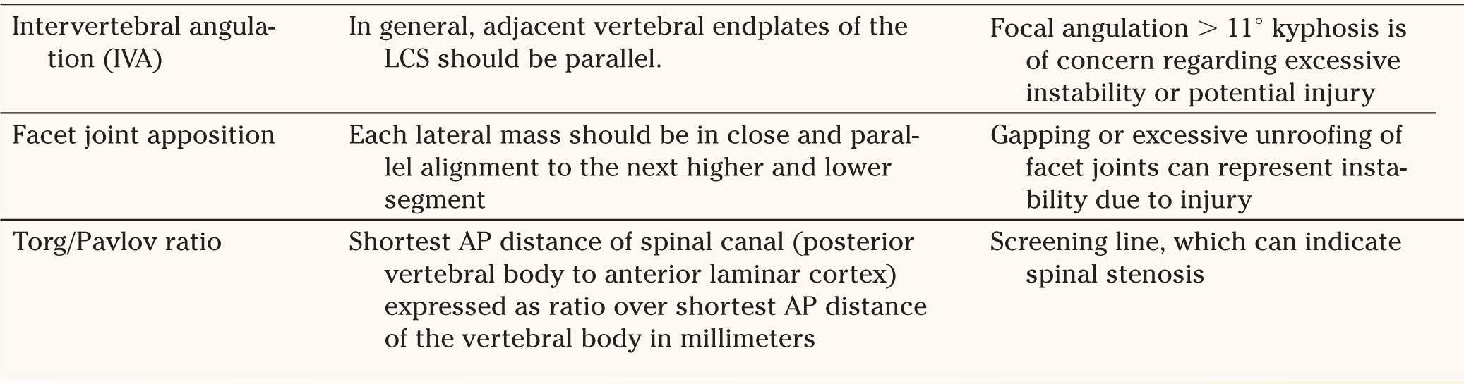
2. AODs or CCDs (Fig. 27-4)
These injuries are always generally considered unstable. There are two main classifications used. The first is that described by Traynelis in 1986 and is descriptive of the position of the skull with respect to the C1 articulation.
• Type I—Anterior displacement of the occiput on the cervical spine (11%)
• Type II—Vertical displacement of the occiput on the cervical spine (3%)
• Type III—Posterior displacement of the occiput on the cervical spine (2%)
• Type IV—Oblique displacement of the occiput on the cervical spine (84%)
A more recent classification is the Harborview classification, which provides stratification based on the severity of ligament injury irrespective of location of the occiput with respect to the adjoining C1 articulations.
• Type I—Incomplete ligament injuries, such as unilateral alar ligament tears. There is sufficient biomechanical stability retained that these can be treated conservatively.
• Type II—Complete CCDs with initial lateral radiographs showing borderline screening measurement values. These injuries, however, feature a complete disruption of key ligaments of the craniocervical junction and are innately unstable. A spontaneous partial reduction of the cranium to its cervical location through some remaining residual ligamentous attachments may provide false reassurance to a reviewer.
• Type IIIa—Complete disruption of craniocervical ligaments with obvious major displacement on plain radiographs with survival of at least 24 hours.
• Type IIIb—Criteria as in IIIa with death from AOD in the first 24 hours following injury.
3. Cl ring fractures—Levine and Edwards (1991) used descriptive anatomic terms to differentiate between fracture subtypes.
• Posterior arch fracture—stable.
• Transverse process fracture—stable.
• Simple lateral mass fracture—A simple fracture is generally stable; however, a unilateral sagittal split fracture may progressively subluxate, leading to a “cock-robin type deformity.”
• Anterior arch fracture—A segmental anterior arch fracture is unstable.
• Comminuted lateral mass fracture—Usually unstable.
• Three- or four-part burst fracture (Jefferson fracture)—A three- or four-part burst fracture is unstable when the TAL is disrupted. This is typically the case if the lateral masses overhang those of C2 by a total of 7 mm or more on an open mouth odontoid view. This well-known finding was originally described by Spence in 1970; although helpful, it was refuted by Dickman et al. in 1996, who showed that many injuries previously thought to be stable really are unstable.
FIGURE 27-4 Classification of occipitocervical dissociation (AOD) according to Traynelis (the bottom row is a parasagittal representation). A Type I injury has anterior displacement of the occiput on the cervical spine. A Type II injury has vertical displacement, and a Type III injury has posterior displacement of the occiput on the cervical spine. Type IV injuries are the most common and display displacement in an oblique plane (not shown). Occult ligamentous damage has to be cautiously evaluated.
4. Atlantoaxial instability—Atlas-dens interval (ADI) in adults should be less than 3 mm; 3 to 7 mm has the potential for a transverse ligament tear, and more than 7 mm is a complete tear. ADI in children should be less than 3 to 5 mm; 5 to 10 mm is a transverse ligament tear; and with 10 to 12 mm, all ligaments have failed.
• Transverse ligament injury
(a) Type I—A Type I transverse ligament injury is a midsubstance or purely ligamentous tear. It usually requires surgical management with C1–C2 fusion.
(b) Type II—A Type II injury is a bony avulsion. Nonoperative treatment is possible.
• Atlantoaxial dissociation—Atlantoaxial dissociation represents a variant of AOD and is highly unstable. Usually, the dissociation occurs in a vertical direction and is accompanied by disruption of the alar ligaments.
• Rotatory translation
(a) Type A—ADI less than 3 mm and the TAL is intact
(b) Type B—ADI 3–5 mm with the TAL insufficient
(c) Type C—ADI greater than 5 mm with failure of the alar ligaments
(d) Type D—Complete posterior displacement of the atlas
5. Fractures of the odontoid (Fig. 27-5)—Classification schemes for fractures of the odontoid are generally based on the level of the fracture as described by Anderson and D’Alonzo in 1974.
• Type I—A Type I fracture occurs at the tip of the odontoid. It is an uncommon injury. Stability is questionable. The clinician should rule out AOD. The differential diagnosis includes os odontoideum.
• Type II—A Type II fracture occurs at the waist of the odontoid. It is the most common type and is easily missed. This fracture is usually unstable. Clinically relevant variables include fracture pattern, displacement, distraction, angulation, and the age of the patient. There is an increased risk of nonunion with this fracture pattern.
• Type III—A Type III fracture occurs through the cancellous body of the axis. This fracture can be relatively stable.
6. C2 ring fractures (Hangman’s fractures)—C2 ring fractures involve traumatic spondylolisthesis of the axis (Fig. 27-6). The classification scheme used was originally described by Effendi in 1981 and further modified by Levine and Edwards in 1985.
• Type I—Type I fractures have less than 3 mm of displacement; there is no angulation. These fractures are relatively stable.
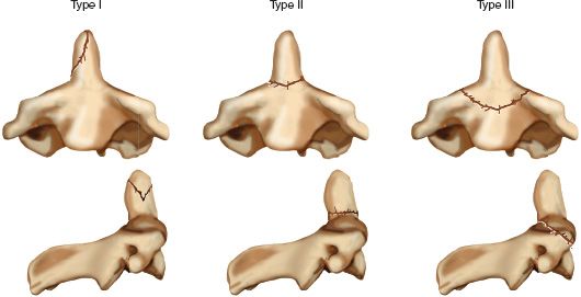
FIGURE 27-5 Classification of odontoid fractures (Anderson and D’Alonzo). Type I, avulsion of the tip (unstable); Type II, waist-line fracture (unstable); Type III, fracture through the vertebral body (conditionally stable).
Related posts:

Stay updated, free articles. Join our Telegram channel

Full access? Get Clinical Tree


