Fig. 8.1
Photographs of retrieved implants, humeral cups, showing magnitude of inferior wear due to boney impingement
The HSS Shoulder Simulator
In order to better understand the biomechanics of the reverse total shoulder arthroplasty, a physical simulator was developed. This built off of our previous work on the function of the rotator cuff. The physical shoulder simulator was first introduced by Hansen et al. [9]. Its purpose was to evaluate the effect of soft tissue changes on the ability of the shoulder to achieve a normal range of motion. In this first study, six cadaveric shoulders were tested in scapular abduction with simulated rotator cuff conditions ranging from an intact rotator cuff to a massive tear of 8 cm. The simulator, with its eight linear actuators, applied force to the joint through the tendons of the rotator cuff and deltoid insertions, while monitoring the position and orientation of the arm in space using electromagnetic motion tracking. The desired abduction angle was entered into the simulator, and an algorithm was then initiated that determined the amount of forces to apply to each tendon in order to achieve that desired position. As the humeral head translated superiorly as detected by the electromagnetic position sensors, the algorithm was found to dictate that the subscapularis had to add force to counteract the humeral head migration and that the infraspinatus and teres minor (TM) would add force to keep the shoulder at neutral rotation. At the time, this was the only simulator that used a closed-loop glenohumeral orientation and translational control strategy; making it unique in that, the forces needed for positional control and stability were calculated dynamically.
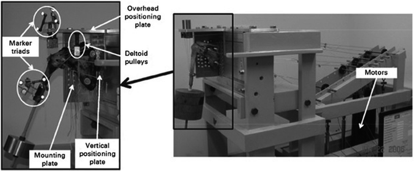
Since its original construction, the HSS Physical Shoulder Simulator has been updated and modified to improve its capabilities allowing us to answer more complex questions and find clinically relevant answers (Fig. 8.2). In its current form, the simulator has 8 electromagnetic stepper motors that serve as linear actuators, thus allowing us to apply simulated muscle forces via spectra cords to the tendinous insertions of up to 8 muscles. In practice, we tend to simulate forces along the lines of action of muscle subgroups, such as superior and inferior portions of the subscapularis, which limits our number of muscles simulated in favor of more accurate representations of the actions of the muscles we do chose to simulate. To enhance the accuracy of these simulated muscle forces, the simulator has been updated with an optimization protocol that uses a physiologic cost function. Optimization using cost functions is common practice in modern musculoskeletal modeling and has been shown to have more biofidelity than using strict muscle force ratios.


Fig. 8.2
Photographs of the HSS physical shoulder simulator. Reproduced with permission and copyright © of the British Editorial Society of Bone and Joint Surgery [10]
Electromagnetic motors were chosen in part due to their rapid response time and ability to hold positions steady. This is opposed to pneumatic actuators that can suffer from both creep and slowed responses depending on the pumps used. The simulator requires these attributes due to the iterative closed-loop methods used in our optimization routines to simulate muscle forces which accurately position the arm in space. To achieve this closed-loop position control, we use visual feedback from reflective marker motion capture. This positional control system monitors the orientation of the humerus relative to the scapula, and the calculated center of the humeral head. The humeral head is limited to 3.0 mm of superior translation as this is the limit of physiologic movement after the rotator cuff has fatigued [4]. To move the arm into the desired position, the simulator calculates the required moments to move the arm in the direction of the desired position, and then a set of actuator forces are applied and the arm is moved. This process is monitored by the motion capture system, and forces are applied and adjusted until the arm is at the desired position. After this, muscle forces are calculated as to minimize the sum of the stresses in all the tested muscles while still achieving the desired position of the humerus. Once the muscle forces are calculated, the actuators apply those forces to the tendon insertion sites. From this, we know the muscular contributions to hold the arm in place, the translation of the humeral head in 3 dimensions, and the joint contact force.
Currently, the HSS shoulder simulator allows us considerable versatility in our choice of research questions. The simulator requires us to give it accurate information about the geometry of the joint. This includes muscle origins and insertions and measurements on the humeral head and glenoid. Because the inputs to the simulator are geometric, any changes to the joint can be made assuming the general mechanics of motion remain the same (i.e., the joint must remain a ball-in-socket joint).
There are some limitations to what can be accurately tested using the physical simulator. Having only 8 actuators limits the active muscle contributions that can be made. Even the passive contributions of muscle tonicity are lost using this, or any cadaver, model; however, all passive constraints on the shoulder can be maintained. Knowing this limitation, great care is taken to choose only the most influential lines of the action to simulate. Issues with muscle wrapping and friction of our spectra cords exist which require us to alter the physiologic path of the muscles to ones that do not impinge on the cadaver. While this adds a degree of error to our model, the linearity of the lines of action allow for more computational resources to be devoted to the optimizations. Finally, the method of optimization using in the simulator limits testing to the use of static positions thus even dynamic tests are calculated in a quasi-static manner.
Research on the Reverse Total Shoulder at HSS: Our First Answers
Many of the concerns published in the observational studies previously mentioned [6, 7] have been the drive of the recent reverse total shoulder research. New questions have also arisen due to the ever-increasing popularity of reverse total shoulder arthroplasty, and its new additional indications. The topics of deltoid deficiency [10], humeral component retroversion [11], and glenosphere positioning [12] and placement [13] have all been published on by our institution in recent years.
Recent indications for reverse total shoulder arthroplasty are complex multipart proximal humerus fractures and revision of failed total and hemi-arthroplasty. Unfortunately, there is the possibility that the deltoid may be damaged. It is well known that the functional outcomes of reverse total shoulder arthroplasty are reliant on the deltoid, and so the HSS Physical Shoulder Simulator was utilized for a study by Gulotta et al. [10] on anterior deltoid deficiency. This study examined the force requirements of the remaining musculature with and without the anterior deltoid in order to determine the efficacy of performing a reverse total shoulder arthroplasty for these new indications in light of possible deltoid deficiency. It was found that the lack of anterior deltoid force production required the middle deltoid (26 %) and subscapularis (82 %) to produce significantly more force to position the humerus at 60° of scaption. For 30° of scaption, under the same conditions, only the subscapularis had a significant increase in required force (192 %); however, the middle deltoid was still heavily taxed. Based on this study, it was felt that every effort to repair and preserve the subscapularis should be made even in light of our previous findings that patients with symptomatic rotator cuff tears have difficulty co-contracting the subscapularis [5].
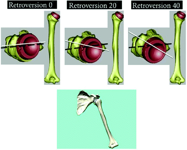
Following reverse total shoulder arthroplasty, scapular notching and limited internal/external rotation continue to be a problem for many patients. In an effort to elucidate solutions to these problems, we have focused on examining the implantation of the prosthesis. The first study performed in this vein was by Gulotta et al. [11] on humeral component retroversion. The HSS Physical Shoulder Simulator was used to simulate muscle loads to stabilize the humerus at 30° and 60° of scaption for 4 positions of humeral component retroversion (0°, 20°, 30°, and 40°). Then, impingement-free internal/external range of motion was measured for each implant configuration, using virtual models constructed from CT images of the specimens. This study showed that humeral retroversion had little effect on muscle forces, possibly dispelling the idea that placing the humeral component in increased retroversion will create a biomechanical advantage for the remaining rotator cuff to initiate active external rotation. The study also showed that retroversion affected impingement-free internal and external rotation in a predictable manner. Increasing retroversion of the humeral component resulted in decreasing amounts of internal rotation at with the arm at the side. Once 60° of abduction was achieved, the humeral bearing was able to rotate unencumbered around the glenosphere. Therefore, impingement of the prosthesis on bone limit rotation is only with the arm at the side. In this position, most patients want to be able to put their arm behind their back, thus efforts to maximize internal rotation should be achieved. Using this clinical logic, the ideal retroversion for the humeral component was determined to be 20° of retroversion. This amount of retroversion allows patients to externally rotate their arm to neutral when at their side, but also maximizes their ability to internally rotate (Fig. 8.3).


Fig. 8.3
Computer modeling of humeral component retroversion. Reproduced with permission and copyright © of the British Editorial Society of Bone and Joint Surgery [10]
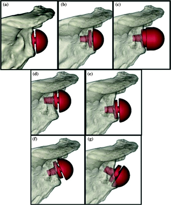
Placement and position of the glenosphere were found to be less adjustable from patient to patient [12]. In this study, the glenosphere was virtually implanted on CT scans of patients. The placement of the glenosphere was offset medial and lateral, translated superior and inferior, and tilted superiorly and inferiorly, for a total of 7 positions. For each of the glenosphere positions, the boney impingement-free range of motion was measured for 0°, 20°, 40°, and 60° of scaption. The study showed that there was inferior impingement of the humeral cup with the scapula at 0° scaption for all configurations except 10 mm of lateralization, 6 mm of inferior translation, and 30° of inferior tilt. These positions also had the greatest internal/external rotation range of motion, with the greatest arc found by inferiorly placing the implant on the face of the glenoid. While this study did not combine positional variations, it would be expected that placing the prosthesis distally and tilting it inferiorly would produce an even larger internal/external rotation arc. The implications that this glenosphere position has on fixation remain to be seen and are the subject of future studies (Fig. 8.4).


