Chapter 22 Biomechanics of the hip, knee, and ankle
When considering orthotic treatment of the lower limbs, an understanding of the biomechanical principles that underpin static and dynamic control of the joints and segments is an essential component of clinical reasoning. This understanding can facilitate the setting of biomechanical goals and the identification of interventions that likely will achieve these goals. Understanding the biomechanics of the lower limb is easier if the topic is divided into manageable portions. Rather than attempting to describe the requirements of control at all joints and segments in all three planes, this chapter focuses on fundamental biomechanical principles, illustrated using clinical examples, which the reader can apply to any problems encountered in his or her own clinical practice.
Basic biomechanical principles
Statics

Moments and levers

In this equation, the distance D (known as the lever arm) is defined as the perpendicular distance from the joint center to the line of action of the force (Fig. 22-1). Therefore, an orthosis that applies oblique, rather than perpendicular, forces will be less effective in generating the required moment because the lever arm will be smaller.
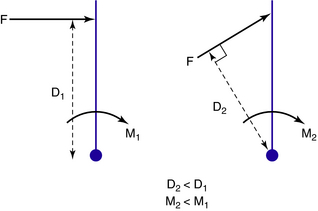
The creation of moments is the critical function of most lower limb orthoses. Increasing the lever arm is a clinically useful strategy because it enables the required moment to be generated while reducing the size of the applied force. Reducing the force reduces the pressure to which the tissue is subjected, with consequent benefits in terms of comfort and tissue viability. Pressure can also be reduced by increasing the area over which the force is applied. Increasing both the lever arm and the area over which force is applied maximizes function and comfort. In practice, of course, the lever arm is limited by the length of the anatomical segments involved or by other anatomical considerations such as tissue intolerance to pressure.
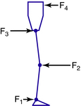
Equilibrium
In order to work successfully, an orthosis must apply a system of forces that have been set up to balance each other, creating a state of equilibrium. This equilibrium relates not only to the forces but also to the moments created by these forces. To control angular motion at a joint, the minimum number of forces required is three, the so-called three-point force system (Fig. 22-2). Two of the forces in this system must be applied on the “concave” side of the joint, and these two forces must be balanced by the third force on the opposite side, which should be located as close as possible to the center of joint rotation. A state of equilibrium is illustrated in Fig. 22-3. Mathematically this state is expressed as follows:
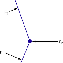
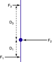
Fig. 22-3 The three-point force system is set up to be in equilibrium so that forces and moments balance.


In Figure 22-3 the three forces in the system are parallel to each other; however, this is not always the case. For example, the forces in the system that control ankle plantarflexion clearly are not parallel to each other, but they act in the same plane and still are in equilibrium (Fig. 22-4). This mechanical principle is known as a triangle of forces. From a practical point of view, in order to balance the other two forces and to “complete the triangle,” the force F2 applied on the dorsum of the foot cannot act in a horizontal direction but must act diagonally downward. To be effective, any ankle strap should be attached in the direction in which this force is required to act.
Shared overlapping force systems
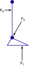
Because three is the minimum number of forces required to control rotation at a joint, one might reasonably assume that control of two joints requires forces to be applied at six places. However, if the two joints are adjacent to each other, some of these forces may be “shared.” This is seen when flexion at the knee and hip must be controlled simultaneously, for example, when using a standing frame, where two superimposed three-point force systems exist (Fig. 22-5). Forces F1, F2, and F3 control knee flexion, while forces F2, F3, and F4 control hip flexion. Thus, while each joint is indeed subject to a three-point force system, only four forces, strategically located, are sufficient to control adjacent joints.
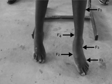
In the above example, the force systems act in the same plane, but this is not always the case. For example, in the valgus foot, the systems that control hindfoot eversion (coronal plane) and forefoot abduction (external rotation in the transverse plane) share a common force (F3) at the lateral calcaneus (Fig. 22-6).
Dynamics
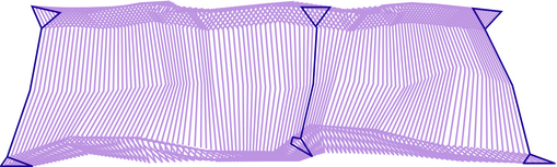
The descriptions of static biomechanics are relevant to almost all situations involving orthoses. However, the treatment of locomotor disorders also necessitates consideration of the dynamic aspects of gait, including the accelerations and decelerations of the limb segments, particularly at specific instances of the gait cycle (Fig. 22-7).
Ground reaction force and moments
Due to gravity, the weight of the body acts vertically downward on the ground. In accordance with Newton’s third law, an equal and opposite force must act upward from the ground on the foot. This is known as the ground reaction force (GRF). Obviously there is no GRF during swing phase. The GRF has a point of application on the foot, or magnitude, and a direction, or line of action (Fig. 22-7). In static situations these all remain constant, with the magnitude equal to body weight. However, in dynamic situations such as locomotion (as will be seen later) they typically vary in a repetitive fashion. When the line of action of the GRF lies at a distance from the center of rotation of a joint, it creates an “external moment.” As we know, the greater the perpendicular distance of the line of action of the GRF to the joint center (the “lever arm”), the greater the external moment will be. If the GRF is aligned close to the joint center, the external moment is smaller. If the GRF passes through the joint center, then no external moment is generated.
During a gait cycle the GRF alignment may pass from one side of the joint center to the other, “switching” moments from, for example, flexion to extension (Fig. 22-8). This implies transfer in neuromuscular demand. For example, the switch from an external plantarflexion moment to an external dorsiflexion moment at the ankle during midstance requires a switch from dorsiflexor activity to plantarflexor activity.
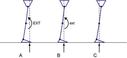
However, the external moment sometimes creates a desirable effect at a joint, reducing or even removing the need for muscle activity. For example, a paraplegic patient fitted with knee–ankle–foot orthoses (AFOs) can achieve hip stability in standing by contriving to align the GRF posterior to the hip joints. At the end of joint range, the internal flexion moment required to balance the external extension moment may be generated (passively) by structures such as the ligaments or joint capsule. A dynamic example can be seen in the late stance phase of gait, when posterior alignment of the GRF to the hip extends and stabilizes the joint without the need for hip extensor activity (Fig. 22-8). This mechanism contributes to the energy efficiency of gait.
The exact magnitude of the external and internal moments (which are mutually dependent) generated at the joints is influenced by the accelerations and inertial effects of the individual limb segments.39 For simplicity, the following discussion of gait ignores these influences. In clinical practice, consideration of the external moments resulting from GRF alignment and their modification by various forms of clinical intervention described later in this chapter can be a successful strategy.3,17,27,34,35
Application of biomechanical principles to normal and pathological gait
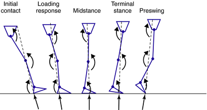
An appreciation of the biomechanical features of normal gait is an essential prerequisite to orthotic management of the lower limb. This chapter focuses on some important observations about normal gait biomechanics, which determine optimal prescription and design of lower limb orthoses. The normal gait of children and adults has been excellently described in depth.10,13,18,32,38 The reader must be clear about the names of each of the phases and subdivisions of the gait cycle and the movements and forces that occur in each of these subdivisions in order to fully understand the concepts that will be discussed.32
Normal gait has been defined as a highly controlled, coordinated, repetitive series of limb movements whose function is to advance the body safely from place to place with a minimum expenditure of energy.11 Five attributes of normal walking have been described: foot clearance in swing, adequate step length, prepositioning of the foot at initial contact, stability in stance, and conservation of energy.11 If we are to replicate these attributes with orthoses, we must understand how they are achieved in normal gait and the extent to which they are interrelated. For example, joint stability is fundamental to stance phase, but it also is a prerequisite for achieving adequate step length in the contralateral leg, which in turn facilitates prepositioning of the swing foot at initial contact.
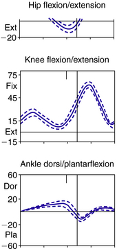
Most texts on normal gait and modern gait analysis focus on the kinematics of the joints, measured as angles between two adjacent segments. Typical graphs for hip, knee, ankle, and foot kinematics then can be produced (Fig. 22-9). However, understanding and giving equal consideration to the kinematics of the segments of the body is key to achieving optimal design of lower limb orthoses (Fig. 22-10). Movement of the segments can be measured relative to the vertical or the horizontal.1,13,39 Measurement of the segment relative to the vertical can be expressed as degrees of incline (leaning forward from the vertical) or recline (leaning backward from the vertical).
Observations of joint kinematics
Normal gait
Kinematic graphs (Fig. 22-9) show the minimum and maximum excursions at all three major joints of the lower limb and their timing in the gait cycle. In the sagittal plane, maximum ankle dorsiflexion occurs in terminal stance, and the ankle is still dorsiflexed when the contralateral leg reaches initial contact. Knee extension is greatest in stance at initial contact and again in terminal stance at 40% gait cycle. At some times in the gait cycle movements are fast, such as knee flexion during preswing and initial swing and ankle plantarflexion in preswing. At other times movements are slow, such as hip flexion in terminal swing and ankle dorsiflexion in terminal stance. At terminal stance the ankle becomes stiffened, which is vital for the production of stability in stance.32
< div class='tao-gold-member'>

Stay updated, free articles. Join our Telegram channel

Full access? Get Clinical Tree


