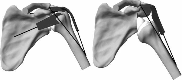
Fig. 10.1
The anatomical prosthesis (left) maintains the anatomical center of rotation of the humerus and the moment arm (M1) of the middle deltoid force (F). The reverse prosthesis (right) displaces the rotation center of the humerus medially and increases by ∆M the moment arm (M2) of the middle deltoid
However, the benefits of the reverse prosthesis are balanced by two important potential drawbacks: a reduced mobility and a lack of glenoid baseplate primary stability. The non-anatomical design of the prosthesis indeed induces mechanical impingements between the humeral component and the glenoid bone, and between the humerus and the scapula. These impingements were related to the observed glenoid notch. Although the baseplate stability was a problem of the initial design that has been solved since then, there is still a fear of unexpected high shear stress at the bone implant interface. The constrained nature of the reverse prosthesis together with the transverse joint forces might indeed cause critical tension and shear around the metallic baseplate.
There are thus still some open questions to improve the RSA prosthesis. The main problem remains the impingements and the associated reduced mobility, compared to TSA. Several design alternatives or modifications are proposed. The problem is complex, however, first not only because of the three-dimensional natural of the problem, but also because of the coupling between impingements and other potential issues of the RSA, such as glenoid baseplate stability, joint subluxation, and/or muscle elongation. There are indeed several other potential problems associated with the non-anatomical prosthesis design: change of muscle moment arms, elongation of the muscles, reaction force within the glenohumeral joint, glenohumeral contact pattern, instability, and wear of the polyethylene insert.
Therefore, a numerical musculoskeletal model of the shoulder was developed to answer these questions. Some general biomechanical questions were analyzed by comparison with the RSA with the TSA. In addition, we investigated more specific questions, associated with the improvement of the design of the RSA, such as the size and position of the glenosphere, or the humeral neck-shaft angle. We analyzed not only the mobility free of impingement, but also the forces in the muscles and in the joint, the stress, and strain within the prosthesis and bone. In the next section, the model will be briefly presented. Then, some general results are presented, to help understand the RSA biomechanics, as compared to TSA biomechanics. The following section is devoted to specific RSA improvements.
The Numerical Musculoskeletal Shoulder Model
We developed a numerical musculoskeletal model of the shoulder from a cadaveric shoulder without any sign of pathology [1–11]. The geometry of the scapula and humerus was geometrically reconstructed from CT scans of this shoulder. The anatomical and reversed Aequalis prostheses (Tornier, Edina, MN, USA) were inserted into this computer model.
To analyze the mobility and impingements of the RSA, passive movements were simulated with the numerical model. Two methods were used. First, the entire three-dimensional space free of impingement was evaluated, using three angular coordinates of the glenohumeral joint (elevation plane, elevation angle, and rotation angle). The position of the humerus was measured according to a reference coordinate system fixed to the scapula [12]. The humerus mobility was analyzed from this three-dimensional space. The conflicting structures were identified and associated with the impingement positions. A second methodology was developed to evaluate the requited angular compensation of the scapula to avoid glenohumeral impingement. This technique was applied to 4 activities of daily living [4].
To analyze the muscle and glenohumeral joint forces, a movement controlled by the muscles was simulated. The following muscles were included into the musculoskeletal model: middle deltoid, anterior deltoid, posterior deltoid, supraspinatus, subscapularis, and infraspinatus combined with teres minor. The model was first used to compare RSA with TSA. For the RSA, the rotator cuff muscles were deactivated (Fig. 10.2). An active and loaded movement of arm elevation in the scapular plane was simulated. The scapulohumeral rhythm was accounted for using experimental data [13]. The arm weight was assumed to be 5 % of the body weight of a 75-kg person. The arm abduction was simulated with or without an additional weight of 1 kg in the hand. During abduction, muscle forces were controlled by a feedback routine, to guarantee muscle activity ratios that were estimated from experimental data [14, 15].


Fig. 10.2
The numerical model of the shoulder, with an anatomical prosthesis (left) and a reverse prosthesis (right). For the reverse prosthesis, rotator cuff muscles were removed [10]
Biomechanics of RSA Compared to TSA
The numerical model was used to answer several biomechanical questions such as the change of the deltoid moment arms, the required muscle forces for a specific movement, the muscle elongation, the joint force, the joint stability (contact pressure), the effect of the scapulohumeral rhythm, the polyethylene wear, and the bone strain.
Moment Arms and Forces
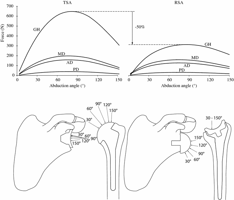
The comparison of the RSA to the TSA with the numerical model provided important elements for a better biomechanical understanding of the RSA. The main difference between the RSA and the TSA is the medial displacement of the rotation center of the humerus. This results in overall increase of the moment arms of the remaining deltoid muscle, between about 10 and 30 mm. As a consequence, the muscle moment arm increase reduced the muscle force required for a specific movement, or weighted equilibrium position. When the rotator cuff muscles are fully deficient, only the deltoid can balance for the arm weight during arm elevation. In this case, our numerical model predicted that the required deltoid force with RSA was approximately the same as it would be for TSA with a fully functional rotator cuff. The increase of the muscle moment arm actually balances for the missing motor function of the rotator cuff muscles. There is thus no change in the deltoid force, but a decrease of about 50 % of the force in the glenohumeral joint (Fig. 10.3). This information on the amplitude of the glenohumeral force was extended by its direction and application point on the articular surfaces. On the glenosphere of the RSA, the joint force has an important infero-superior contribution, while this force is mainly latero-medial for the TSA. In the humeral side, the joint force of the RSA remains located in the inferior part of the humeral cup, as soon as the elevation is initiated. In the resting position of the arm, our model predicted that the non-anatomical design of the RSA displaced the humerus inferiorly by 38 mm. The displacement of the humerus lengthened the middle, anterior, and posterior deltoid by, respectively, 34, 30, and 23 mm. If still functional, the subscapularis and infraspinatus were also elongated by 20 and 21 mm.


Fig. 10.3
Top glenohumeral (GH), middle deltoid (MD), anterior deltoid (AD), and posterior deltoid (PD) forces during abduction, for TSA (left) and RSA (right). Bottom orientation of GH force at 30°, 60°, 90°, 120°, and 140° of abduction [10]
Glenohumeral Contact Pattern and Subluxation
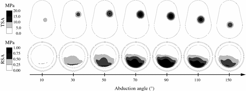
The evaluation of the contact pattern is important as it may predict the risk of subluxation. The glenohumeral contact pattern on the polyethylene component of the RSA is consistent with the predicted joint force. It remains located in the inferior side polyethylene component during the elevation of the arm (Fig. 10.4). For the TSA, the model predicts a typical inferior–superior–inferior cycle, which has been reported by other models, cadaveric or in vivo measurements [16–18]. The glenohumeral contact pressure for the RSA does not exceed 1.2 MPa, at 90° of abduction, while it reaches 19 MPa for the TSA. Overall, the articular contact pressure is approximately 20 times lower for the RSA than for the TSA. This drastic decrease of the contact pressure is explained by the decrease of the joint force and the increase of the articular contact area. The opposing articular surfaces of the RSA have indeed the same radius of curvature, while a radial mismatch of about 5 mm is usually recommended in the TSA.


Fig. 10.4
Scapulohumeral Rhythm
The scapulohumeral rhythm has been reported to be changed after the RSA [19, 20]. This could of course affect the predictions of the biomechanical models. An inversion of the scapulohumeral rhythm was simulated with the numerical model. The commonly accepted rhythm of 2:1 (glenohumeral to scapulothoracic) was replaced by 1:2. This means that two-thirds of the humerus elevation angle is obtained by the rotation of the scapula. According to the model’s predictions, there is nearly no effect on the glenohumeral force and contact pattern for the RSA. Conversely, for the scapulohumeral rhythm, inversion induces a higher (23 %) glenohumeral force and an eccentric postero-superior contact pattern for the TSA [21].
Polyethylene Wear
Since polyethylene wear is a known issue in TSA, its importance in RSA was evaluated. Practically, the amount of polyethylene wear caused by the abrasion of the metallic sphere of the RSA was simulated and compared to the prediction for TSA [9]. An experimental polyethylene wear law was implemented within the model [22]. Experimental measurements of the daily frequency of the abduction levels were simulated to reproduce one year of activities of daily living [23]. After one year of activities of daily living, the maximal depth of PE wear is not exceeding 0.13 mm with the RSA, while it is 0.2 mm with the TSA. However, since the wear area is higher in the RSA than in the TSA, the predicted volume of polyethylene wear is more than 5-fold higher in the RSA than in the TSA. The values predicted for the TSA are in agreement with other models, as well as with clinical reports. For the RSA, these predictions should be clinically confirmed. Only wear caused by surface abrasion was reproduced here, which is actually very limited (<50 mm3) compared to the destruction of the polyethylene associated with the scapular notch.
Impingements and Mobility
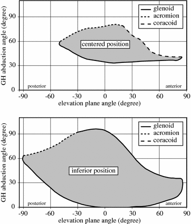
The impingement, and the so-called scapular notch, is the main issue of the non-anatomical design of the RSA. Initially, the baseplate of the glenoid sphere of the RSA was positioned in the middle of the glenoid. It was later assumed that impingements might be reduced by a displacement of the baseplate at the most inferior limit of the resected glenoid. Full mobility of the glenohumeral joint was evaluated, in the three axes of rotation, for the two positions of the baseplate: centered and inferior. For the centered baseplate, adduction induced impingements between the humeral prosthesis and the glenoid bone (inferior, anterior, or posterior) and between the greater tuberosity and the acromion or the scapular spine. Flexion induces impingements with the coracoid process. Internal or external rotation (15°) slightly decreases the impingements in flexion or extension, without modifying the impingements in abduction–adduction. For the inferior baseplate, impingements are less important. In abduction, the impingements with the coracoid are avoided, and the impingement with the inferior border of the glenoid is reduced. The range of flexion–extension in the horizontal plane is also increased, but not the range of elevation in the coronal plane. The inferior baseplate extends approximately threefold the volume of space reachable by the arm. The impingement map obtained with the numerical model confirms and extends cadaveric measurements [24]. Although the inferior baseplate reduces the risk of impingement, it remains a problem, not only with the inferior part of the glenoid, but also with the anterior and posterior glenoid, the coracoid process, the acromion, and the spine of the scapula. The inferior impingement has been associated with the inferior glenoid notch, but the superior impingement between the greater tuberosity and the acromion could explain the fractures of the acromion reported in the literature [25]. These results demonstrate that impingements caused by reversed constrained prostheses are clearly a three-dimensional problem, which can be efficiently analyzed by numerical modeling. This analysis could significantly improve the design and the surgical techniques of the RSA (see Fig. 10.5).


