Fig. 31.1
a short-neck scapula b long-neck scapula
Therefore, we can mention the existence of a real “critical zone” that we have deliberately chosen to resurface to neutralize this problem (Fig. 31.2).
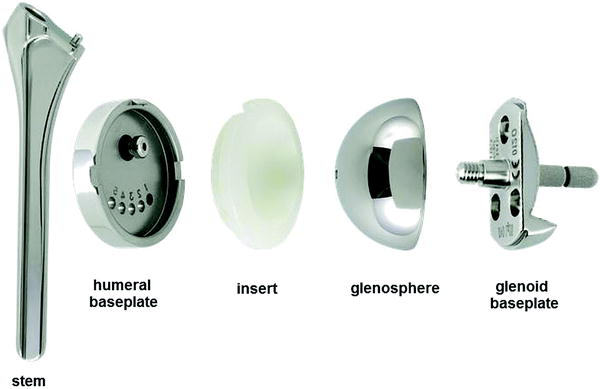

Fig. 31.2
The elements of the Duocentric prosthesis
The Prosthesis
To address this specific problem, we started developing the Duocentric® Reversed prosthesis (Aston Medical) in 2001. These efforts led to the first implantation of a third-generation prosthesis called the Duocentric® prosthesis in 2003, as a follow-on to the “Trumpet” and Delta® (DePuy). After a few more improvements, the Duocentric® Expert Reversed became available in 2007.
Materials
Polyethylene ultra-high molecular weight (UHMW) (ISO 5834-1 and ISO 5834-2) is used for the humeral insert. Stainless steel is used (ISO 5832-9) for the humeral stem, baseplate, glenosphere, assembly, and bony screws. Hydroxyapatite coating is for the stem and double coating of pure titanium and hydroxyapatite for the glenoid baseplate. To facilitate trials, various possible size combinations can be identified by a color code (Fig. 31.3).
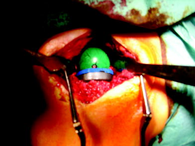

Fig. 31.3
The trial elements of the prosthesis with their color code
The Glenoid Component
This prosthesis provides an original solution to the notching problem—a spherical inferior overhang integrated onto the glenoid baseplate (Fig. 31.4), which places a protective resurfacing shield over this critical area in the scapular pillar at the start of adduction. This overhang also increases the primary stability of the implant by counteracting the shearing forces at the implant–glenoid interface. But, this modification requires a brief historical look back for context. With the first generation of reverse prosthesis, notching was minimal, rare, and non-progressive since its two-thirds sphere of 44-mm-diameter design automatically provided this resurfacing (coincidental prevention). This complication only truly appeared once a one-half sphere was used in the second generation, Delta-type prosthesis.
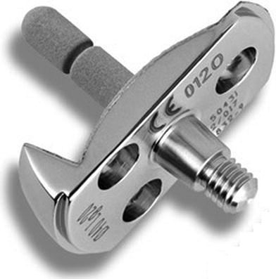

Fig. 31.4
The glenoid baseplate
The convex pattern of the baseplate, central peg, and the lower ledge has the advantage of providing additional primary stability before screw fixation. It is fixed with a breakaway peg and three screws (Fig. 31.4). The lower edge increases the bony contact surface. A convex-backed glenoid baseplate improves the contact surface at the bone implant interface as compared to a flat-backed design, so contributing to good bone ingrowth for long-term glenoid fixation. The glenoid baseplate has a porous dual-layer titanium-hydroxyapatite coating (Fig. 31.4); a biomechanical study demonstrated that a convex-backed glenoid leads to stress transmission in compression more than shear as compared to a flat-backed design [11].
The Humeral Component
Other than its unique inferior overhang, this prosthesis also has a low metaphysis volume, a cemented or cementless stem with a self-stabilizing cross-sectional shape, and a 145° neck-shaft angle which is a compromise between stability and mobility. These features have been devised to increase the active range of motion, limit the risks of dislocation and glenoid loosening, and to meet the primary objective of reducing the notching effect. The standard Duocentric® instrumentation also contributes to achieving these goals by making it easier to implant the glenoid baseplate in the lower part of the glenoid bone and by preparing the seat of the inferior overhang (Figs. 31.5 and 31.6).
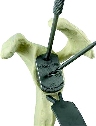
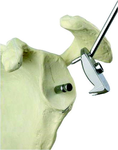

Fig. 31.5
The ancillary instrument with the lower retractor, for preparing the inferior overhang place

Fig. 31.6
The central pin
Put the forked retractor in an inferior position (Fig. 31.5). Determine the size of glenoid cavity, 36 or 40 mm Ø, using the gauge based on the bone coverage. The inferior edge of the selected gauge should come to the inferior edge of the glenoid; the inferior edge physically represents the cutting level of the scapula pillar, which is the superior part of the lower rim of the glenoid baseplate. It does not represent the low position of the glenoid baseplate itself. Then, we drill the central hole using the 3.5 mm Ø drill to a depth of at least 15 mm (Fig. 31.6).
Stay updated, free articles. Join our Telegram channel

Full access? Get Clinical Tree


