and Ajay Aggarwal3
(3)
Department of Orthopaedic Surgery, University of Missouri, Columbia, Missouri, USA
1.1 Fracture Implants
Take-Home Message
Modulus of elasticity for cortical bone is ~20 GPa, stainless steel ≈ 200 GPa, and titanium ≈ 100 GPa
Bending stiffness of plates ≈ thickness of the plate3
Bending stiffness of intramedullary nails ≈ radius4
Modulus of Elasticity
Stress = force/area
Strain = change in length/original length
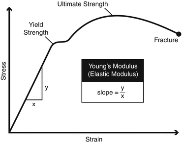
Modulus of elasticity (Young’s modulus) = stress/strain. Most solid material has a linear portion of its stress-strain curve (Fig. 1). This portion is the slope of the curve and the elastic modulus (E). Hooke’s law of elasticity indicates that no permanent deformation/damage occurs within the linear area of the curve.

Fig. 1
Stress–strain curve (© Copyright 2014 by The Curators of the University of Missouri, a public corporation, with permission)
Yield and Ultimate Strength
Once a material is loaded past the elastic portion of the stress-strain curve and there is permanent damage to the material (plastic deformation), it reaches its yield point.
If loading continues past the yield point, the material will eventually catastrophically fail and that is the ultimate strength.
Ductility: amount of plastic deformation tolerated before ultimate failure.
Brittle materials: high elastic modulus, low ductility = stiff but fail at yield point
Ductile materials: lower elastic modulus, larger area of plastic deformation before ultimate failure = flexible and deform prior to ultimate failure.
Fatigue Strength or Endurance Limit
Materials can withstand cyclic loading until microdamage accumulates causing rapid failure. The fatigue strength/endurance limit is the maximum stress the material can withstand without failure after 10–100 million cycles.
Plates
Extramedullary, usually load-bearing devices
Bending stiffness ≈ to plate thickness3
Ex: Increasing the thickness of a plate by 2 mm increases the bending stiffness eight times the original.
Intramedullary Nails
Intramedullary, usually load-sharing devices
Bending stiffness = π × radius4
Ex: Increasing the radius of an IM nail by 2 mm increases the bending stiffness by 16 times.
Common Fracture Implant Materials
Stainless steel: elastic modulus ~200 GPa, plates, and screws
Stiff and more brittle
Risk of rejection if patient has a nickel allergy
Titanium: elastic modulus ~100 GPa, intramedullary nails, and plates and screws
Flexible and more ductile.
Titanium resists corrosion.
Titanium forms passivation layer to inhibit bacterial colonization.
Used in nickel-allergic patients.
Risk of cold welding that makes implant removal difficult.
1.2 Arthroplasty
Take-Home Message
Highly cross–linked polyethylene liners have performed well in vivo. Wear is significantly lower compared to conventional polyethylene. Fracture of highly cross-linked polyethylene occurs and is multifactorial.
Metal–on–metal (MOM): Worldwide reduction in utilization of MOM is due to concerns about adverse local tissue reactions (ALTR) secondary to wear and/or corrosion of cobalt-chromium-based components. Elevated metal ions can cause pseudotumors and aseptic lymphocytic vasculitis-associated lesion (ALVAL).
Ceramic–on–ceramic: Is an attractive option for young and active patients. The most significant disadvantage is the potential for fracture and squeaking.
Polyethylene Processing
Polyethylene is a long-chain hydrocarbon. When exposed to radiation, carbon–carbon and carbon–hydrogen bonds can be broken. As a result, chain scission or free radical formation can occur. Oxygen can bind at a free radical site, leading to oxidation. Both chain scission and oxidation have negative consequence for wear and mechanical properties.
Cross-linking involves formation of carbon–carbon bonds between two adjacent polyethylene polymers. Irradiation is the first step and produces free radicals. Free radicals then react and cross-link the polymer chains. The amount of cross-linking is proportional to the radiation dose. Doses of 50–100 kGy (5–10 mrads) are typically used. Heating is the second step, and it reduces the free radicals and thus decreases the risk of oxidation.
Conventional Polyethylene
Radiation dose between 2.5 and 4.0 mrads.
Disadvantage: Higher linear and volumetric wear leading to increased incidence of osteolysis and loosening.
Highly Cross-Linked Polyethylene
Radiation dose between 5.0 and 10.0 mrads.
Advantage: Markedly decreased linear (<0.004–0.25 mm/year) and volumetric wear. Smaller wear particles decrease the risk of osteolysis and loosening.
Disadvantage: Decreased mechanical properties leading to reduced strength, fatigue resistance, and fracture toughness. Fracture of polyethylene has been associated with suboptimal positioning of components, implant design with sharp corners at the locking mechanism, and thin polyethylene.
Vitamin E Polyethylene
Vitamin E helps in stabilizing the free radicals without postradiation melting and maintains the mechanical properties of polyethylene. Vitamin E highly cross-linked polyethylene demonstrates oxidative resistance, good strength, and low wear.
Metal-on-Metal (MOM)
Stay updated, free articles. Join our Telegram channel

Full access? Get Clinical Tree


