Fig. 1.1
The femoral rollback can be simplified and described in a two-dimensional (2D) four-bar linkage system
Knee kinematics can be characterised by a coupled internal rotation and roll-gliding motion during flexion.
More recent studies have shown a significant difference between the knee kinematics of the medial and lateral compartment [3] (Fig. 1.2).
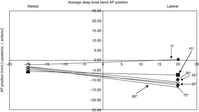
Fig. 1.2
Characteristic kinematics of knee flexion with a pivoting of the medial compartment and an interplay of rolling and gliding of the lateral compartment [3]
The medial femoral condyle predominantly rotates and demonstrates minor translation during flexion. In contrast, the lateral condyle rolls and glides posteriorly on the tibial plateau. The different kinematic behaviour in the medial and lateral compartments lead to coupled internal rotation of the tibia in relation to the femur during flexion.
The tibia performs a coupled internal rotation during knee flexion.
The condyles are almost spherical during the range of motion between 20° and 120° of knee flexion. The condylar axis passes through the lateral epicondyle at the attachment site of the lateral collateral ligament and through the medial condyle at a point approximately 13 mm more distally and posteriorly from the medial epicondyle (Fig. 1.3).
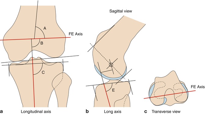
Fig. 1.3
Flexion and extension axis of the knee joint showing (a) the frontal view of the longitudinal axis of the tibia in red, in relation to the epicondylar axis of the femur, (b) the sagittal view of the same longitudinal axis in the tibia with the femoral rotation axis in relation to the femoral anterior and posterior geometry, and (c) a view of the femoral epicondylar axis in the transverse plane
Most activities of daily living (ADL), such as ascending or descending the stairs or rising from a chair, require a flexion of the knee between 0° and 120°. However, there are a number of common activities that require a greater flexion angle of up to 140°, such as kneeling, squatting or sitting cross-legged [4].
The flexion arc may be subdivided into three sections. The first section ranges from full extension (hyperextension) to approximately 20° of flexion, which is the load-bearing activity when walking [5]. The active arc ranges from 20° to approximately 120° and is under full muscular control. The swing phase of gait ranges from toe off (TO) to heel strike (HS), making up just under 40 % of the gait cycle. The flexion required to walk is up to 70°, in order to keep the toes clearly of the ground. Finally, the passive arc, which ranges up to an average maximum of 145° in Caucasians and 160° in Asians, is used mainly for squatting or kneeling and is limited by impingement of the soft tissues at the popliteal region in the calf. However, deep flexion is a very important aspect for religious and social reasons, especially in Asian culture.
Kinematic changes occur after TKR, due to the fact that either anterior or both cruciate ligaments are resected. With both preserved, the surfaces of the TKR replace the stabilising factors of the natural condylar surfaces and menisci. With only the posterior cruciate ligament (PCL) intact and the anterior cruciate ligament (ACL) resected, the TKR should restrain the tibia from abnormal anterior translation. With both cruciates resected, the restraint must additionally apply to tibial posterior translation [6]. The ACL primarily restrains anterior tibial translation but controls tibial internal rotation as well. In case of ACL deficiency, the neutral position of the tibia to the femur is translated more anteriorly and rotated internally when compared to its position in an intact knee. In vivo assessment of the kinematics in normal and ACL-deficient knees showed less anteroposterior translation in the lateral compartment but increased translation in the medial compartment in the ACL-deficient knees. Furthermore, axial femorotibial rotation is significantly decreased during deep flexion [7].
1.2 Design of the Components
Analysis of TKR design includes the constraints that the individual components incorporate and the flexion kinematics imposed by the shapes of the bearing surfaces, contact areas, wear, effects of variation of joint and muscle forces on the stability of the TKR and alignment characteristics. The fixation of the components to the bones must withstand these loads and last for many years. That is not straightforward, because the presence of fixation stems will alter the mechanical environment of the adjacent bone. This may lead to bone loss due to ‘stress shielding’ [8], which is a reduction in bone density caused by the removal of normal stress from the bone by the implant.
1.2.1 Femoral Component
For primary and revision surgery, numerous component designs have been developed, the posterior cruciate retaining, the posterior stabilised, the total stabilised and the rotating hinged knee (Fig. 1.4).
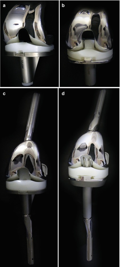
Fig. 1.4
TKR design variations, (a) showing a posterior cruciate retaining design (top left), (b) posterior stabilised design with the post-cam interface in the centre (top right), (c) condylar constraint stabilised with a box design offering no axial rotation (bottom left), and (d) rotating hinged knee with a fully constrained design (bottom right)
TKR component designs can be differentiated in posterior cruciate retaining, posterior stabilised, total stabilised and rotating hinged TKR.
In the cruciate-retaining design (CR), the PCL is preserved. With an insufficient or absent ACL, the tibia is put at risk of abnormal anterior translation. In order to counter that tendency, the tibial PE bearing surface retains a concavity, which stabilises the femoral condyles against excessive anteroposterior translation during flexion–extension. An unfortunate side effect is that the physiological rollback of the femur over the tibial plateau during knee flexion is inhibited by the upward slope of the posterior edge of the bearing surface. This deviation from normal kinematics leads to impingement of the posterior aspect of the femur against the rim of the tibial tray, which limits the range of knee flexion and can lead to paradoxical anterior translation of the femur on the tibial bearing surface. Fluoroscopy studies have revealed that most posterior stabilised configurations feature a paradoxical slide forward motion when knee flexion starts, instead of the intended mimicking of the natural knee rolling back on the tibia with increasing flexion [9–13]. Taking this into consideration Bellemans et al. [14] suggest that the posterior offset (distance which the femoral component protrudes posteriorly from the femur) should be increased, to delay this impingement and allow more knee flexion, offering an increase in posterior offset.
In the posterior stabilised (PS) design, both ligaments are resected. The function of the PCL is mimicked using a vertical post in the centre of the tibial component and a crossbar (CAM) in between the posterior condyles of the femoral component (Fig. 1.5).
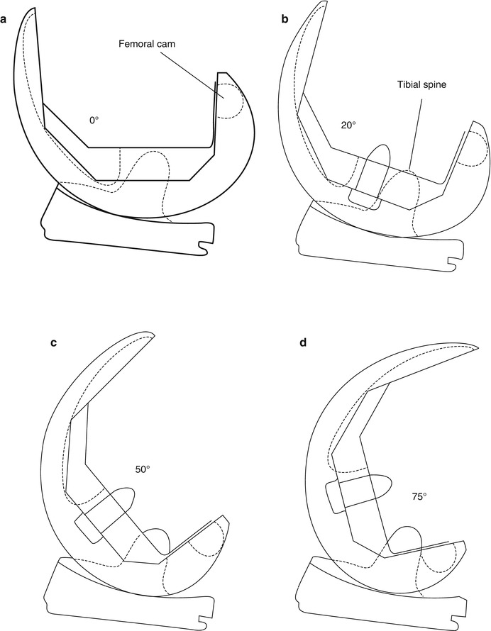
Fig. 1.5
In the posterior stabilised (PS) design, both ligaments are resected. The function of the PCL is mimicked using a vertical post in the centre of the tibial component and a crossbar (CAM) in between the posterior condyles of the femoral component. The components can interact freely in extension (a), similar to unconstrained TKRs. During flexion (b, c) the component geometries interact in accordance with the ligamentous and muscular constraints surrounding the knee. In deep knee flexion (d) the cam engages with the tibial post and prevents further anterior gliding of the femoral component in relation to the tibia
The post acts as a passive restraint to tibial anteroposterior motion, because the femoral component in this type of TKR has a central ‘box’, which must be inserted deeply into the centre of the distal femur to accommodate the tibial post. At the posterior outlet of the intercondylar notch, this type of femoral component has a cam acting against the posterior face of the tibial post. This mechanism forces the femur to roll/glide posteriorly during knee flexion, but it does not accommodate the remaining lack of ACL stabilising restraint. In addition, the fit of the post inside the femoral box reduces freedom of IE rotation. Clinical follow-up studies have shown that the PS design allows increased flexion in comparison to the CR design.
The total stabilised design is primarily used in knees presenting insufficient collateral ligament support, such as when either collateral ligaments are damaged, or in severe varus or valgus deformity with significant elongation of either one of the collateral ligaments (see Chap. 54). The knee stability is recouped by the central post of the PE inlay. Due to limited knee mobility in the sagittal plane, the bone–component interface is subject to increased stresses, which may cause early aseptic loosening.
To avoid such stress increases, the rotating hinged knee was developed in order to allow combined free rotation in both flexion and extension (see Chap. 55).
1.2.2 Tibial Component
The tibial component is affected by large cyclic loading during gait. This repetitive strain may lead to micromotion at the bone–implant interface. The peak forces during walking are 3–4 times body weight (BW) [15]. These forces can increase up to more than 4 times body weight when descending downstairs or 8 times BW when tripping [16].
Axial loading can reach up to 8 times body weight.
During flexion–extension of the knee, resulting joint forces in AP direction can lead to a rocking motion of the components. The resulting micromotion at the interface may subsequently cause loosening.
Increased fixation stability may be achieved using a larger-sized fixation stem. However, reverting to a larger-sized component should only occur when a regular size would be insufficiently supported by the prevalent posterior tibial bone stock. A long fixation stem may cause ‘stress shielding’, which triggers resorption of bone from the area below the proximal tray of the tibial component due to the load passing along the stem into the tip [17].
Offset stems are very common based on the centre of the diaphysis not coinciding with the centre of the metaphysis. The centre of the diaphysis lies approximately 4.1 mm more anteromedially at an average angle of 105° [18]. The usage of cement is a common point of discussion for revision TKR. Where the cement undoubtedly offers to fill gaps where bone stock is lost it also typically does not encounter any bone ingrowth. Moreover, using an increased volume to fill any gaps at the bone–implant interface, the additional temperature increase caused by the polymerisation process can harm the surrounding cells significantly.
1.2.3 Inlay
There are two types of inlay, the fixed and mobile bearing. The fixed-bearing inlay can be flat or dished design (Fig. 1.6.). The flat design does not restrict femoral motion and thus decreases the stress between the tibial component and underlying bone. However, high-load transmission occurs due to the small contact area between the inlay and femoral component. The dished design increases the contact area but reduces AP translation, which in turn increases the bone-implant interface stress of the tibial component. As mentioned earlier, a lack of femoral rollback may limit greater knee flexion. The use of mobile bearings has been proposed to overcome this limitation. The PE bearing has a range of freedom in moving in the AP direction and/or allowing for rotation of the tibial plateau, compensating for a limited femoral rollback. The intact collateral ligaments and muscles around the knee joint thereby have greater freedom to allow a more natural kinematic knee flexion. In addition, it has also been postulated to be more forgiving in terms of femoral rotational malpositioning. A comparison of the in vivo kinematic performance of fixed- and mobile-bearing TKRs has found that the mobile-bearing implants were closer to the kinematic behaviour of the intact knee [19], which could explain clinical differences in patient outcomes [20]. However, when implanting a TKR with a freely rotating PE inlay, Walker et al. [6] demonstrated experimentally that static friction would inhibit the inlay from rotating: friction was only overcome at a level of torque higher than that at which the body would normally prevent any further rotation through soft tissues and muscle action.
 Laboratory Analysis in the Assessment of Painful Total Knee Replacement
 Discussion to Chap. 52: Patellofemoral Pain After Cruciate Retaining Total Knee Replacement
 Joint Line Restoration in Revision Total Knee Replacement
 Discussion to Chap. 34: Persistent/Recurrent Pain After TKR Not Always TKR Related
 Use of Stems in Revision Total Knee Replacement
 Periprosthetic Fracture Treatment in Total Knee Replacement


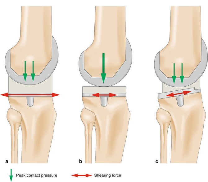
Fig. 1.6
Deep dished (a) and flat (b) inlay. The deep dished inlay shows larger contact area but more stress between the tibial plateau and the bone than the flat inlay. The contract stress is much higher with the flat inlay due to the small contact area. The mobile bearing inlay (c) allows an increase in contact area without increasing stress between the implant and bone
Related posts:
Laboratory Analysis in the Assessment of Painful Total Knee Replacement
Discussion to Chap. 52: Patellofemoral Pain After Cruciate Retaining Total Knee Replacement
Joint Line Restoration in Revision Total Knee Replacement
Discussion to Chap. 34: Persistent/Recurrent Pain After TKR Not Always TKR Related
Use of Stems in Revision Total Knee Replacement
Periprosthetic Fracture Treatment in Total Knee Replacement
Stay updated, free articles. Join our Telegram channel
Full access? Get Clinical Tree
