Analyzing the Nasium X-Ray
Kirk Eriksen
Roderic P. Rochester
Learning Objectives
After studying this chapter, the reader should be able to:
Draw an accurate Atlas plane line.
Construct a central skull line and measure the degree of Atlas laterality.
Measure the degree of head tilt found on the nasium film.
Determine the lateral misalignment between atlas and axis, represented as the Lower angle.
Measure the spatial orientation of the atlas vertebra.
Determine the geometry of the articulating surfaces in the upper cervical spine.
Measure the rotatory and lateral deviation of the axis odontoid relative to the atlas and skull.
Use Computer-aided digitization in the analysis of the upper cervical Subluxation.
The Orthospinology procedure is a method of correcting the occipito-atlanto-axial Subluxation complex, which is based on the pioneering research and teaching of the late Dr. John Francis Grostic. It is actually a series of steps in the total care of the patient and is therefore a chiropractic procedure and not simply a spinal adjusting technique. The procedure employs a method of X-ray analysis that quantifies the lateral and rotational misalignments between atlas and occiput, as well as atlas and axis. The analytical procedure examines the spatial orientation of the atlas, the geometry of the articulating surfaces, and the misalignment configuration to arrive at an effective correction vector. In addition to the radiographic protocol, the system contains steps for ensuring the precision of the X-ray analysis, adjusting methods, and postAdjustment re-evaluation procedures. This allows the doctor to assess the effectiveness of the Adjustment and fine-tune the correction to the individual patient. The Orthospinology X-ray analysis is the real core of the procedure and is the one area that has remained the most constant for more than 60 years.
This chapter reviews the steps that are essential for measuring upper cervical alignment in the frontal plane. These procedures include determining the acceptability of the image and the protocol for identifying structures for measurement purposes. Strict adherence to this process is necessary to compute the optimal Adjustment vector. The Nasium view provides information about the biomechanical component of the occipito-atlanto-axial Subluxation complex. This includes Atlas laterality, axis odontoid deviation, axis spinous process rotation, lower-angle deviation, the spatial orientation of the atlas in the frontal plane, and the geometry of the upper cervical Articulations.
Atlas Plane Line
The nasium X-ray is first assessed to determine if the film is acceptable for analysis. This process is covered in Chapters 3 and 8. Assessment includes verifying that the radiograph is properly exposed and developed, all structures are properly placed, the posterior arch of the atlas is acceptable, and Image rotation is no more than 1°. The first step in the nasium analysis is to locate the inferior attachments of the atlas posterior arch. Grostic found that these were the most reliable points to be used for determining the spatial orientation of the atlas. These important attachment points are found at the junction of the inferior aspect of the posterior arch and the lateral aspect of the atlas lateral masses (Fig. 5-1).
This is accomplished by following the posterior arch from the medial to lateral aspect. Do not confuse these points with the transverse process root attachments. The atlas posterior arch attachment points should then be carefully marked bilaterally.
This is accomplished by following the posterior arch from the medial to lateral aspect. Do not confuse these points with the transverse process root attachments. The atlas posterior arch attachment points should then be carefully marked bilaterally.
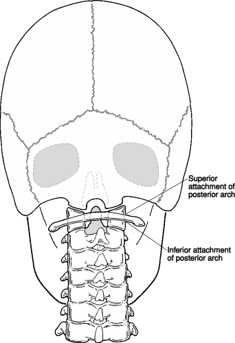 FIGURE 5-1 Atlas posterior arch points. |
It should be noted that every pencil mark that is made in the Orthospinology analysis should be made with a sharp X-ray pencil, and the point should be made as small as possible to improve the precision of the mensuration. Draw the Atlas plane line (APL) by connecting each posterior attachment point with a triangle or straight edge. This line should horizontally cross the entire film (Fig. 5-2). A pencil mark should then be made at the junction of the superior posterior arch and the atlas lateral mass on each side. A triangle should be lined up on these points, and a line should be drawn from each lateral mass outward to the edge of the film. This superior line represents a double check for the inferior line. These two lines will be parallel in most cases, unless the posterior arch is bilaterally asymmetrical or the points were selected improperly. Indeed, if the lines are not parallel, then check to make sure that the posterior arch points were correctly marked.
 FIGURE 5-2 Drawing inferior and superior Atlas plane lines. |
Central Skull Line and Atlas Laterality
A Central skull line (CSL) must be constructed by using a template or computer-aided digital analysis. The first step involves locating and marking the temporal-parietal sutures on each side of the cranium with a short diagonal line. The portion of the skull above these suture points will be used to determine the central axis of the skull. This distance is usually between 1 and 2 inches and is dependent on the shape of the head. The portion of the skull that tapers in at the top should not be used in the analysis. The lateral regions below the temporal-parietal suture marks and the vertex area of the skull are not considered to be reliable because of structural asymmetry (Fig. 5-3).
Place the Orthospinology analysis instrument (OAI) (Fig. 5-4) on the nasium X-ray so that matching arcs of the instrument closely fit on the surfaces of the parietal bones for a distance of 1 to 2 inches above the suture line. This is accomplished by first finding a set of like reference points and arcs on the OAI that are superimposed
on the film just above the temporal-parietal suture marks. These arcs need to be matched up equally on each side of the skull. Next, rotate the instrument until the other reference points, along the matched arcs, are equidistant to the skull bilaterally. When the doctor is satisfied that the template has accurately framed the lateral parietal bones, draw a preliminary line in the OAI center slot. This initial line should be drawn from the APL up about 1 inch; a second line is made in the upper slot about 2 inches long. If the width of the central slot is wider than a pencil point, always use the same side of each central slot to guide the marking pencil.
on the film just above the temporal-parietal suture marks. These arcs need to be matched up equally on each side of the skull. Next, rotate the instrument until the other reference points, along the matched arcs, are equidistant to the skull bilaterally. When the doctor is satisfied that the template has accurately framed the lateral parietal bones, draw a preliminary line in the OAI center slot. This initial line should be drawn from the APL up about 1 inch; a second line is made in the upper slot about 2 inches long. If the width of the central slot is wider than a pencil point, always use the same side of each central slot to guide the marking pencil.
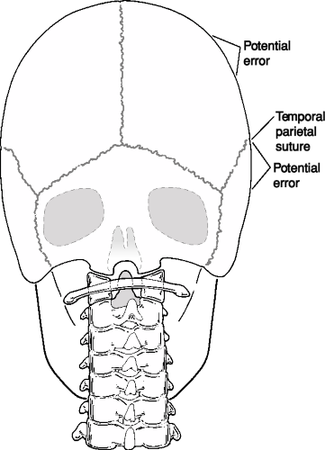 FIGURE 5-3 Appropriate and inappropriate regions of lateral skull to use in constructing central skull line. |
The CSL needs to be rechecked by moving the OAI up and down along these preliminary lines to make sure that a new set of reference points match with each side of the skull. Rotate the OAI by pivoting around the initial reference points until the best curve fit is achieved (Fig. 5-5). A final line will then be drawn from the APL up to the top of the film. Use a protractor to measure the Atlas laterality by lining up its horizontal axis with the APL at the intersection of the CSL (Fig. 5-6). Atlas laterality with respect to the skull is measured on the side of the acute angle and is quantified as the amount the angle varies from 90°. List the Atlas laterality in the upper quadrant of the film on the side of the acute angle with the prominent letters At L or At R and the number of degrees. Figure 5-6 shows an Atlas laterality of 3°.
Head Tilt
Measuring head tilt in the frontal plane is a valuable assessment in the management of patient care. The side and amount of head tilt provides information about the nature of the Subluxation and how the patient should be placed on the headpiece (see Chapter 12). It is also important to be able to quantify any changes in skull deviation from the pre- and post-X-rays. This will help to determine whether the Adjustment or patient placement is responsible for changes in the APL (see Chapters 8 and 20). The measurement can be accomplished by lining up the horizontal axis of the protractor with the top edge of the film at the intersection of the CSL (Fig. 5-7). The amount of head tilt is determined by the side of the obtuse angle and is quantified as the amount the angle is >90°. This measurement should be listed as R or L on the side of the head tilt at the top of the film by the CSL. Figure 5-7 shows 1° head tilt to the left.
Lower Angle
The lateral misalignment between the atlas and axis is measured by drawing a line from the center of the axis through the center of the seventh cervical vertebra. This measurement is known as the Lower angle. The first step in this analysis involves placing a mark on the lateral margins of the right and left zygapophyseal joints of C7. The ruler on the bottom of the OAI can be used to bisect the two points to find the center of the seventh cervical vertebra (Fig. 5-8). Mark the center with a pencil dot.
Next, place a dot on the superior/lateral margins of the body of C2 (Fig. 5-9). Bisect these two points to find the center of the axis body. This dot should be in the center of the odontoid at its base in 80% to 90% of the patients. If the axis center mark does not agree with the center of the dens, recheck the lateral points carefully by following the lateral edge of the atlas lateral masses downward to help locate the axis lateral borders. If the center of the base of the odontoid is still not the same as the center of mass of C2, then the doctor should suspect an abnormally developed axis odontoid. A special note is required in large letters—Abnormal Od Right or Left of Center. The degrees of deviation from the C2 body center of mass should then be noted. This should be listed in the upper quadrant opposite the side of Atlas laterality. It can be written as an abbreviation (e.g., ABN Od R3).
The next step involves marking a dot at the superior tip of the axis spinous process (Fig. 5-9). It may be necessary to look at the lateral cervical X-ray and compare the position of the axis spinous tip relative to the atlas Sagittal plane line (Fig. 5-10). Transpose the measurement
from the lateral view over to the nasium film, and this will enable the doctor to know where to look for the axis spinous compared with the APL. However, this measurement from the lateral view will be magnified if the X-ray is taken at a 42-inch focal film distance as opposed to 72 inch. Another method used to assist in locating the axis spinous process involves visually following the spinous processes from C7 to C2. They should follow a continuous pattern in most cases (Fig. 5-10).
from the lateral view over to the nasium film, and this will enable the doctor to know where to look for the axis spinous compared with the APL. However, this measurement from the lateral view will be magnified if the X-ray is taken at a 42-inch focal film distance as opposed to 72 inch. Another method used to assist in locating the axis spinous process involves visually following the spinous processes from C7 to C2. They should follow a continuous pattern in most cases (Fig. 5-10).
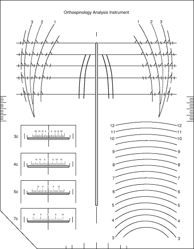 FIGURE 5-4 Orthospinology analysis instrument. |
Bisect the distance between the odontoid (assuming it is not atypical) and the spinous process points by placing a dot in the center (Fig. 5-9). The middle point represents the center of the spinal canal because the odontoid point represents the anterior aspect and the spinous process point represents the posterior aspect of the axis vertebra. Finally, construct a line through the C2 and C7 midpoints. This line should intersect with the APL (Fig. 5-11). Using a protractor, measure the angle formed by the lower-angle line and the APL (Fig. 5-12). List the measurement on the side of the acute angle in the lower quadrant with an R or L, then the number of degrees measured away from the 90° mark. Figure 5-12 shows a lower-angle deviation of 4° to the left.
Atlas Plane Line Measurement
Method One
The next step in the procedure is to determine how the APL compares with a horizontal plane on the nasium X-ray. There are two methods to accomplish this step, and
both are reliable. Most doctors use the first method because it is a little quicker; the second method requires the use of a calculator.
both are reliable. Most doctors use the first method because it is a little quicker; the second method requires the use of a calculator.
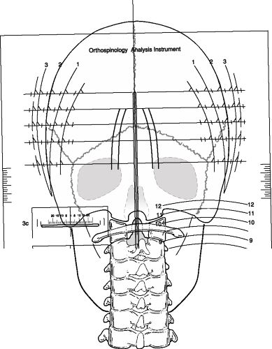 FIGURE 5-5 Using the Orthospinology analysis instrument to construct central skull line.
Related posts:Stay updated, free articles. Join our Telegram channel
Full access? Get Clinical Tree
 Get Clinical Tree app for offline access

|
