Analyzing the Lateral Cervical X-Ray
Kirk Eriksen
Learning Objectives
After studying this chapter, the reader should be able to:
Draw an accurate atlas Sagittal plane line and determine the appropriate angle for taking the nasium film.
Locate the atlas transverse process, and record it on the patient’s Listing card.
Determine the relationship of the axis spinous process relative to the S-line.
Assess the pathological integrity of the lateral and anteroposterior (AP) cervical X-rays.
Develop an appreciation for the clinical significance of the sagittal cervical curve.
The lateral cervical X-ray provides the doctor with potential pathological and biomechanical information that will aid in the care of the patient. This chapter will provide a brief overview of the steps involved with assessing the osseous integrity of the cervical spine. The lateral radiograph also provides information about the Sagittal plane of the atlas vertebra, which is measured so that this angle can be used to determine the Central ray for the nasium film. This slope is necessary to project the image of the atlas posterior arch so that the inferior attachment points are clearly visible on the nasium X-ray. These points are critical in the analysis of the nasium because they will be used to construct the Atlas plane line. The Lateral cervical view will also allow the doctor to find the atlas transverse process in its relationship to the Mastoid process and ramus of the mandible. This information is essential for determining the contact point for delivering the Adjustment. The biomechanics and clinical significance of the lateral cervical curve will also be reviewed in this chapter.
Atlas Sagittal Plane Lines
The lateral cervical film must be analyzed to determine the superiority or inferiority of the atlas in the Sagittal plane relative to the skull. These Atlas plane lines are divided into two categories: lines projecting above the hard palette are S (or superior), and lines below the hard palette are I (or inferior). An atlas Sagittal plane line projecting through the hard palette is considered an S0. However, the atlas presents in the superior plane in the vast majority of cases, so this line is generally referred to as an S-line. To determine the appropriate S-line for each case, the doctor must first determine if the X-ray was taken properly (see Chapter 3, Figs. 3-5 and 3-6). The structure of the cervical spine should be adequately visualized, and all seven cervical vertebrae need to be present (except with rare patients). The doctor should verify that the film does not have significant head tilt or rotation. An initial cursory evaluation of the film, from a pathological standpoint, should be conducted to screen for any unusual findings. The doctor will conduct a more thorough pathological evaluation later when he/she has ample time before initiating care.
The first step in constructing the S-line involves placing a small pencil dot at the inferior junction of the posterior arch and the lateral mass. A second dot is placed on the inferior margin of the posterior arch about 1/4 inch posterior to the initial point (Fig. 4-1). A line is then drawn with a straight edge through these two dots and extended anteriorly through the facial structures. This line should also extend posteriorly past the axis spinous process (Fig. 4-2). This will aid
the doctor in locating the C2 spinous process point on the nasium film (see Chapter 5 and Fig. 5-10). The facial structures through which this line passes should be compared with the S-line chart (Fig. 4-3). The S-line that most closely matches the patient’s configuration is marked on the X-ray. It should be noted that if the line is between two S-lines, then the S-line with the greater value should be used. However, a plus and minus system of notation can also be used (e.g., S2+ or S3–).
the doctor in locating the C2 spinous process point on the nasium film (see Chapter 5 and Fig. 5-10). The facial structures through which this line passes should be compared with the S-line chart (Fig. 4-3). The S-line that most closely matches the patient’s configuration is marked on the X-ray. It should be noted that if the line is between two S-lines, then the S-line with the greater value should be used. However, a plus and minus system of notation can also be used (e.g., S2+ or S3–).
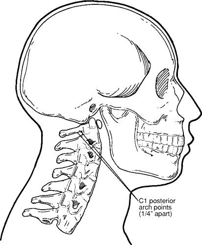 FIGURE 4-1 Marking points on the atlas posterior arch for constructing the S-line. |
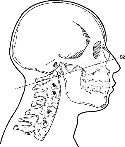 FIGURE 4-2 Drawing the S-line from the posterior cervical spine through the facial structures. |
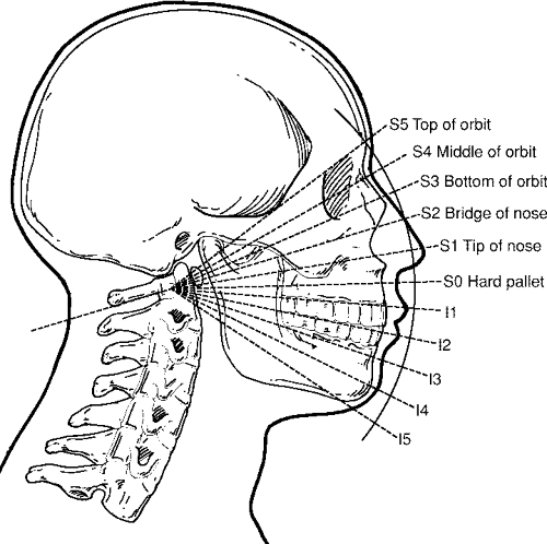 FIGURE 4-3 S-line chart. |
The lateral cervical film should be observed to determine if any teeth project along the pathway of the S-line. This is a common occurrence with young children, and wisdom teeth must be identified in adults. If this is the case, the S-line should be raised so that it will project over the teeth to avoid the atlas posterior arch attachment points from being obscured on the nasium X-ray. The doctor may be faced with a dilemma in the rare case of a patient presenting with an atlas Sagittal plane line that is lower than an I1. Most of these cases will cause the teeth to superimpose over the atlas vertebra and prevent an accurate analysis. The doctor must choose between two options. The nasium can be taken above an I1, although this could cause the atlas posterior arch to project a bit too high, depending on the patient’s true I-line. Another option is to setup the X-ray tube so that the Central ray projects through the patient’s mouth as it is opened for the view. Once again, these cases are extremely rare.
Locating the Atlas Transverse Process
The location of the atlas transverse process is also determined from the lateral cervical X-ray. It should be noted that due to magnification and the thickness of the connective tissue over the Mastoid process, the palpated location of the tip of the mastoid would not match its projection on the radiograph. As an option, the doctor can tape a piece of lead shot over the tip of the Mastoid process to view its projection on the Lateral cervical view. This will enable a more precise view of these anatomical structures to aid in the localization of the atlas transverse process. The atlas transverse process should be outlined on the radiograph as well as the Mastoid process (Fig. 4-4). The lead shot that was taped to the anterior/inferior corner of the patient’s earlobe (see Chapter 3, Fig. 3-2) will provide another landmark point on the lateral X-ray (Fig. 4-5). This will also be used as a reference point to help locate the patient’s atlas transverse process. This is a critical procedural step because the accuracy of this contact point is necessary in the successful delivery of an upper cervical Adjustment.
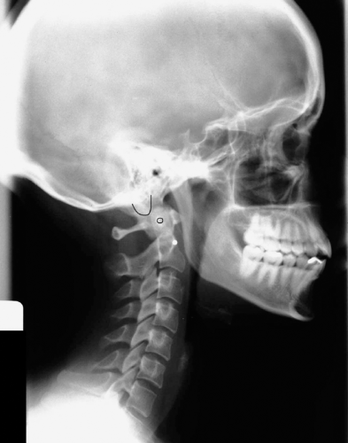 FIGURE 4-4 Outlining the atlas transverse process and the Mastoid process. |
Pathological Assessment
The lateral view is also used to evaluate the cervical spine for normal architecture, fractures, and arthritic changes, as well as intra- and extraosseous masses. The doctor must make an attempt to determine the safety and appropriateness of chiropractic care, along with assessing the misalignment components of the Subluxation. Dr. Christopher Kent1 provides a thorough checklist for assessing lateral cervical radiographs in Tables 4-1 and 4-2. Tables 4-3, 4-4, 4-5 and 4-6 provide a detailed checklist for a pathological assessment for the AP open-mouth and AP lower cervical views.
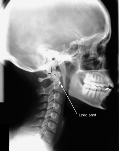 FIGURE 4-5 Lead shot on the anterior/inferior corner of patient’s earlobe as seen on X-ray. |
The incidence of significant pathological findings on spine X-rays has been reported to be rare, and as a result, various authors have reported on the overuse of radiography in chiropractic and medical practice.2,3,4,5,6,7 However, current research casts some doubt on this contention. In a study of 1,004 random patient files (between 1997 and 2001) from the outpatient clinic at the New Zealand College of Chiropractic, radiographic anomalies were found in 68% of the patients that had film taken.8 Absolute contraindications to Spinal manipulative therapy were found as follows: fracture (6.6%), malignant tumor (0.8%–3.1%), abdominal aortic aneurysm (0.8%), and atlantoaxial instability (0.6%).
TABLE 4-1 Checklist for the Lateral Cervical Radiograph | |||||||||||||||
|---|---|---|---|---|---|---|---|---|---|---|---|---|---|---|---|
|
TABLE 4-2 Conditions That Demonstrate Findings on the Lateral Cervical Radiograph | ||||||||||||||||||||||
|---|---|---|---|---|---|---|---|---|---|---|---|---|---|---|---|---|---|---|---|---|---|---|
|
TABLE 4-3 Checklist for the AP Open-Mouth Radiograph | ||||||
|---|---|---|---|---|---|---|
|
TABLE 4-4 Conditions That Demonstrate Findings on the AP Open-Mouth Radiograph | ||||||||||
|---|---|---|---|---|---|---|---|---|---|---|
|
TABLE 4-5 Checklist for the AP Lower Cervical Radiograph | ||||||||||
|---|---|---|---|---|---|---|---|---|---|---|
|
TABLE 4-6 Conditions That Demonstrate Findings on the AP Lower Cervical Radiograph | |||||||||||
|---|---|---|---|---|---|---|---|---|---|---|---|
|
Related posts:

Stay updated, free articles. Join our Telegram channel

Full access? Get Clinical Tree


