FIGURE 9-1. Diagram demonstrating insertion of a threaded polyethylene liner extractor. The extractor is threaded through a modular polyethylene liner to contact the underlying metal shell. Continued threading of the device provides a distraction force to the liner (top). Additional toggling of the extractor facilitates liner removal (bottom).

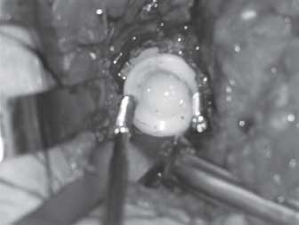
FIGURE 9-2. Intraoperative photograph demonstrating the use of 6.5-mm-diameter cancellous screws to extract a modular polyethylene liner from the metal acetabular shell.
As a last resort, the acetabular liner may be removed by sectioning the polyethylene liner with a high-speed burr and removing it in multiple sections. Disadvantages of this technique include the generation of significant polyethylene debris as well as the potential for damaging the locking mechanism or surface finish of the underlying metal shell. Surrounding the periphery of the acetabulum with moistened sponges within the wound prior to sectioning the liner can limit seeding of the wound with particulate polyethylene debris.
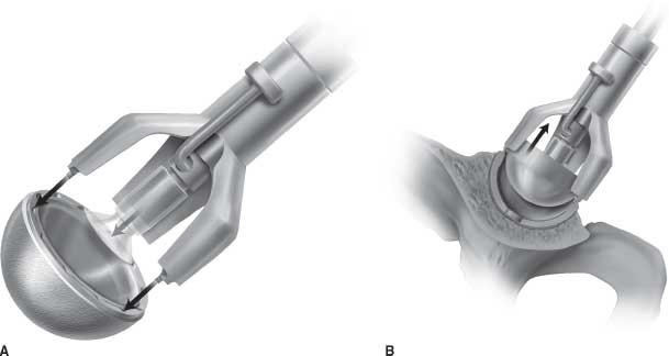
Metal Liner Exchange. With increasing use of hard-on-hard bearing surfaces, the surgeon must be aware of techniques for removal of modular metal and ceramic liners as traditional liner removal techniques described above for polyethylene liners are not applicable. Since the modular fixation mechanism of metal liners usually involves use of a smooth taper lock (no polyethylene ridge interdigitations or locking rings), the techniques recommended for removal of a metal liner from a well-fixed cup involve disrupting the smooth taper using a vibratory stimulus. Impacting the rim of the acetabular component with a rigid, metallic punch may disrupt the taper lock of a metallic liner. Component-specific extraction devices are also available and are typically provided by implant manufacturers. The majority of these extractors are applied to the peripheral rim of the acetabular component and the surgeon applies an impac-tion force resulting in a peripheral vibratory force that will disrupt the taper lock of the metal liner and allow liner removal (Fig. 9-3A,B).
FIGURE 9-3. Diagram demonstrating use of an extraction device utilized for removal of hard bearings. The device contacts the peripheral rim of the metal acetabular shell (A). An impaction force is then applied, resulting in a peripheral vibratory force that disrupts the taper lock of the metal bearing (B).
Ceramic Liner Exchange. Exchange of ceramic acetabular liners share many of the same techniques utilized in removal of modular polyethylene or metal liners. In designs in which the ceramic insert is embedded within a modular polyethylene liner, techniques previously described for removal of modular polyethylene liners can be utilized. The majority of currently available modular ceramic liners, however, are fixed directly to the metal acetabular component (without an intervening layer of polyethylene) using a taper lock mechanism and are extracted using similar techniques described for modular metal liner removal. However, if the ceramic liner is fractured, this may preclude the effective use of commercially available extractors. The presence of a ceramic crack may allow vibratory stimuli to dissipate via the fracture interfaces, preventing disruption of the taper lock of the component to the metal shell. In this circumstance, direct impact on the liner or acetabular component rim with a metal punch will hopefully provide enough vibratory force to dislodge the remaining ceramic fragments to permit piecemeal removal.
Once the liner has been removed, the acetabular shell must be thoroughly evaluated for conditions that may preclude liner exchange. If the locking mechanism is damaged or if significant burnishing of the shell has occurred from wear of the femoral head, the shell may require revision despite being well fixed and appropriately oriented. Additional indications for complete component removal include designs in which the locking mechanism is intact, but of poor design, or if a new appropriate liner is not available due to shell geometry or insufficient polyethylene thickness. One alternative to shell revision in those cases is cementation of an alternative liner into the existing shell. Lastly, if the shell is well fixed but mildly malpositioned, consideration may be given to insertion of an extended lipped liner or adjustment of femoral component anteversion (if femoral component is also being revised) to obtain stability without shell revision.
Complete Component Removal The most common acetabular components utilized currently are modular, hemispherical, press-fit metallic acetabular shells with polyethylene, metal, or ceramic bearing liners locked into the metal shell. Cemented acetabular component designs include either nonmodular, metal-backed components or all polyethylene acetabular components. Acetabular component design variances present differing challenges for component removal and will determine the appropriate method for component removal. Press-fit acetabular components can have fixation augments including screws, fins, or spikes interrupting the hemispherical contour of the cup. These irregularities will impact instrumentation options and considerations if removal instruments designed to follow the contour of the acetabular component are used.
The primary goal in component removal is minimization of bone destruction and preserving as much host bone as possible for fixation of the revision component. The width of the fixation-dividing instruments, how well they contour to the geometry of the acetabular component, and the thoroughness of the disruption of the prosthesis-cement or bone-prosthesis interface are all variables that will impact the degree of host bone destruction sustained during the process of component removal.
Multiple different techniques have been described for acetabular component removal. Some of these techniques are common to both cemented and press-fit components, while others are specific to one or the other.
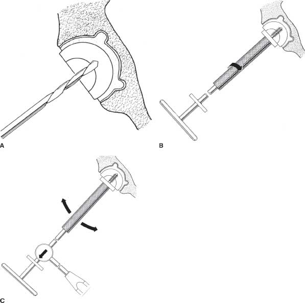
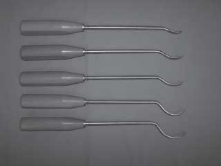
Cemented Acetabular Component Removal. A key principle in removal of cemented acetabular components is to initially disrupt the prosthesis-cement interface, which permits removal of the component. The cement is then secondarily removed under direct vision. Adoption of this principle prevents unnecessary bone removal, which often results if the cement-bone interface is initially blindly disrupted. The most commonly used methods for cemented polyethylene acetabu-lar component removal involve utilization of curved acetabu-lar osteotomes that have a similar contour (hemispherical) as the implanted acetabular component (Fig. 9-4) or the use of a threaded acetabular component extractor (Fig. 9-5A–C). Using this tool, an initial pilot hole is drilled into the center of the polyethylene component. The extractor is then threaded into the pilot hole and a separate sleeve is then threaded down the shaft of the extractor and tightened against the rim of the component. The entire assembly is then toggled as a unit, distributing the levering stress against the entire component. The component with attached cement may then come free as a unit, or the prosthesis-cement interface may be disrupted leaving all or part of the cement bed in place. Remaining cement is then removed under direct vision.3,4,6,7
FIGURE 9-4. Photograph of hand-guided curved acetabular osteotomes utilized to disrupt the fixation interface of well-fixed acetabular components.

FIGURE 9-5. Diagrams demonstrating use of a threaded extractor for removal of cemented polyethylene acetabular components. A drill hole is drilled into the center of the acetabular component (A). The extractor is then threaded into the drilled hole until the metal plate is flush with the rim of the acetabular component (B). The extractor is then toggled to disrupt the fixation interface and remove the component (C).
Another described technique involves using acetabular reamers to progressively thin the cemented polyethylene component. After the component is appropriately thinned, the underlying cement can be visualized through the residual polyethylene and the polyethylene and cement can be “easily removed using hand tools.”8
Sabboubeh and Khatib9 have described a technique using multiple 2.5-mm drill holes placed into the cemented polyethylene component (especially into the component rim) and subsequently introducing and removing 4.5-mm fully threaded cortical screws into each hole. This progressively disrupts the prosthesis-cement interface. The process is repeated until the component begins to lift out. They note that with advancement of the screws, the cement mantle will often crack, facilitating extraction, and sometimes results in removal of the entire cement mantle with the component. They report successful use of this technique in 20 cases without complication.9
Stay updated, free articles. Join our Telegram channel

Full access? Get Clinical Tree


