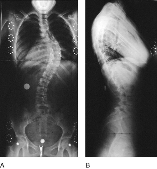
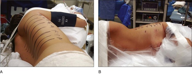
• Scoliosis greater than 70–80° • Thoracic lordosis greater than 10–20° • Thoracic hyperkyphosis greater than 90° Pitfalls • Figure 1 shows standing PA (Fig. 1A) and lateral scoliosis (Fig. 1B) radiographs of a 15-year-old patient with Lenke 1A adolescent idiopathic scoliosis. • The instrumentation end vertebrae can also be planned using these radiographs. • An axillary roll is placed under the left axilla and both shoulders and elbows are flexed 90°. • A pillow is placed between the elbows and one large “jelly” roll is placed behind the patient’s shoulders and another in front to help hold the position. • Four-inch cloth or silk tape is placed over the right shoulder to maintain the lateral position. • The C-arm is brought in and placed into the lateral position (PA of the thorax). A line is drawn down the center of the spine over the levels to be fused. The C-arm is rotated to the anteroposterior (AP) position and the center of each vertebral body is marked with a straight line parallel to the end plate from the posterior to the anterior thorax. The intersection of these lines and the line along the posterior axillary line is the location of the posterior portals, which will be primarily used for screw placement (Fig. 6A).
Thoracoscopic Release and Instrumentation for Scoliosis
Indications
 Thoracoscopic anterior release (diskectomy)
 Thoracoscopic instrumentation for adolescent idiopathic scoliosis
Examination/Imaging
 A complete neurologic examination of the trunk and lower extremities, including abdominal reflexes, needs to be performed.
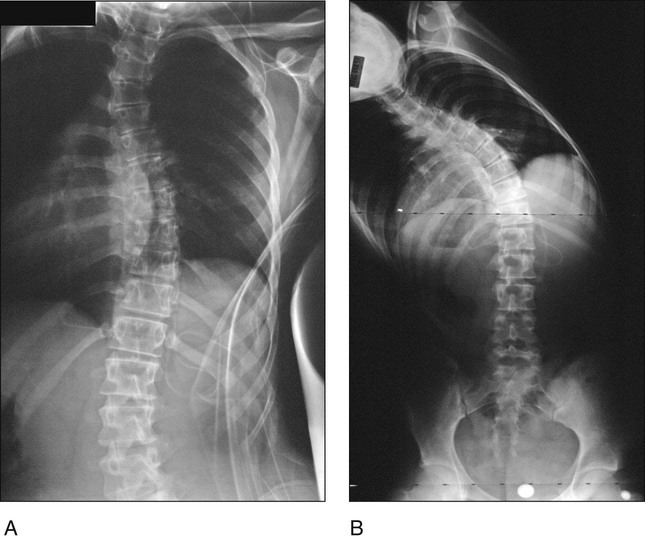
 Left and right bending films are obtained to determine the flexibility of the compensatory upper thoracic and lumbar curves as well as the flexibility of the main thoracic curve. Figure 2 shows left (Fig. 2A) and right (Fig. 2B) bending films of the same patient as in Figure 1.
Surgical Anatomy
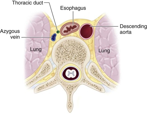
 Figure 3 is an anatomic sketch of the right hemithorax demonstrating the major structures.
 The lung must be deflated prior to exposure and completely reinflated at the time of closure.
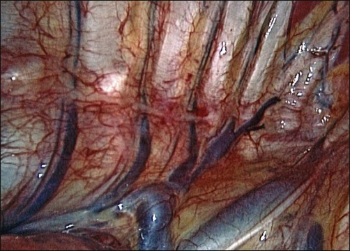
 The azygos vein is located anterior and slightly to the right of the vertebral bodies (Fig. 4). This large and friable vein is the most posterior longitudinal vessel in the right hemithorax. It receives intercostal vessels cepahalad to the T6 level (sometimes lower).
 The esophagus runs anterior to the vertebral column between the azygos vein and descending aorta.
 The sympathetic chain runs on both sides just anterior to the costovertebral joints.
Positioning
 The lateral decubitus position is described here because it facilitates retraction of the lung and great vessels and is the preferred position of the authors.
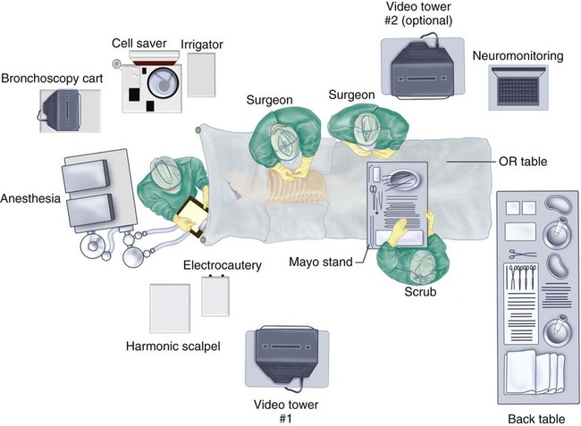
 The operating room table is placed in the center of the room parallel to its long axis. Monitors and other equipment are positioned as shown in Figure 5.
 Double-lumen endotracheal tube placement is performed in the supine position.
 For most situations, the patient is placed on the left side.
Portals/Exposures
Related posts:
 4: Open Reduction and Internal Fixation of Displaced Medial Epicondyle Fracture Using a Screw and Washer
29: Epiphysiodesis of the Distal Femur/Proximal Tibia-Fibula
32: Patellar Instability: Lateral Release and Medial Plication
31: Discoid Lateral Meniscus
39: Open Reduction and Internal Fixation of Tibial Tubercle Fractures
59: Posterior Instrumented Reduction and Fusion for Spondylolisthesis
4: Open Reduction and Internal Fixation of Displaced Medial Epicondyle Fracture Using a Screw and Washer
29: Epiphysiodesis of the Distal Femur/Proximal Tibia-Fibula
32: Patellar Instability: Lateral Release and Medial Plication
31: Discoid Lateral Meniscus
39: Open Reduction and Internal Fixation of Tibial Tubercle Fractures
59: Posterior Instrumented Reduction and Fusion for Spondylolisthesis
![]()
Stay updated, free articles. Join our Telegram channel

Full access? Get Clinical Tree


60: Thoracoscopic Release and Instrumentation for Scoliosis


