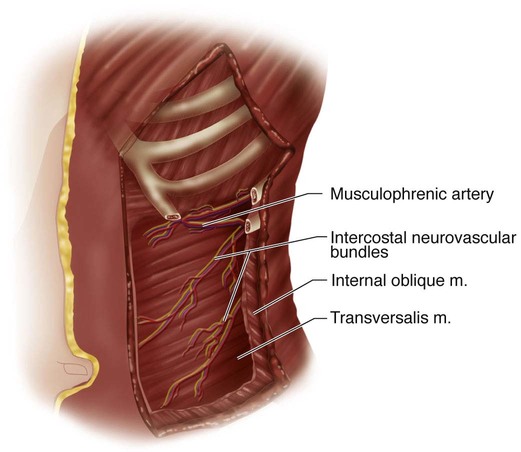
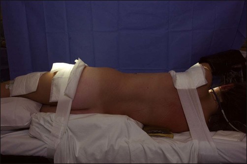
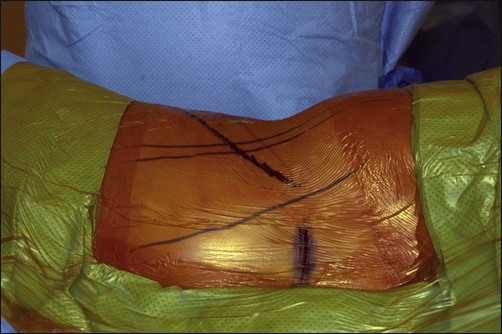
• The standard technique is to include the entire Cobb measurement. • Hall et al. (1997) described a technique for short-segment selective instrumentation. In their initial discussion, structural curvatures greater than 60° and thoracic curvatures that did not correct to 20° or less on the corrective radiographs were excluded. The criteria are based on both the standing posteroanterior (PA) and the supine anteroposterior (AP) bend radiographs. • The end instrumented vertebrae are often short of the Cobb terminals. In order to avoid imbalance, the deformity must be overcorrected by about 10°. This will frequently create an adjacent wedged disk space. • Either single-rod or dual-rod instrumentation may be used. In the patient in Figure 5A–D, the dual-rod system required no structural graft to maintain the sagittal alignment. We have not been able to obtain the same amount of coronal plane correction (overcorrection) with the present dual-rod systems. Controversies • Comparable results may be obtained with posterior pedicle screw constructs. In the patient in (Fig. 6A–D, the excellent correction required a five-segment construct. A similar result might have been obtained with a posterior pedicle screw constuct. • The relative benefit of sparing a motion segment at the expense of subjacent disk wedging is not known; there is uncertaintly about the benefit of the short-segment overcorrection technique versus the Cobb method. • Once they leave the ribs and costal cartilage, the intercostal neurovascular bundles pass obliquely across the abdominal wall in the interval between the internal oblique and transversalis muscles. The 10th bundle is directed to the level of the umbilicus, the 9th several centimeters above, the 11th between the umbilicus and pubis, and the 12th toward the inguinal area. • The musculophrenic branch of the internal mammary artery and its vein lie behind the costal arch between ribs 7–10 and anastomose with the intercostal vessels. It must be cauterized or ligated when the arch is divided. • Intercostal nerves 7–12 innervate the rectus muscle, penetrating it at its lateral border. Incisions along this semilunar line will denervate the muscle. • The flat radiolucent table shown in Figure 9 permits biplanar imaging. The patient is placed in the lateral decubitus position with bolsters holding the pelvis. The upper torso is taped. A roll is positioned several fingerbreadths below the axilla. • A conventional table permits better support via kidney rests and may first be flexed to facilitate the approach and then lowered to allow the spine to fall into a corrected position prior to instrumentation manipulation. • Entry level selection: A horizontal line is drawn from the curve apex (see dashed line in Fig. 1A). The rib on the convexity of the deformity that is intersected at the lateral-most portion of the standing PA radiograph is selected. In general, the 9th rib is used when exposure of the T11-12 level is required, and the 10th rib for the T12-L1 level.
Anterior Spinal Instrumentation and Fusion for Lumbar and Thoracolumbar Idiopathic Scoliosis
Indications
 Structural idiopathic lumbar or thoracolumbar scoliosis (TL/L) (Lenke 5) that has failed conservative treatment and/or has progressed to a degree associated with progression in adulthood.
 Selective treatment of TL/L scoliosis with associated thoracic curvatures.
 Standing PA radiograph: Select the apex. If this is a disk space, include the two cephalad and caudal vertebral bodies (four bodies, three disks). If a vertebral body, include one cephalad and one caudal segment (three vertebrae and two disks).
 Supine AP active bend: Include those interspaces that do not “reverse.”
 When levels between the two views differ, choose the longer of the constructs.
 This technique will often save one or even two motion segments.
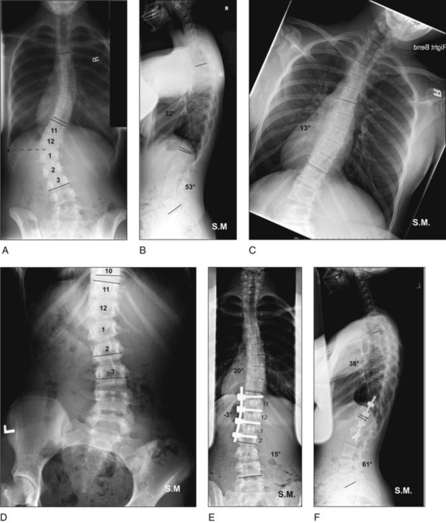
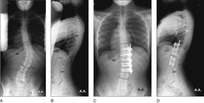
 An example of the short-segment technique is shown in Figure 1. The end vertebrae are T11 and L3. On the standing PA view (Fig. 1A), the apex is the T12-L1 disk. The levels are two above and two below: T11-L2. On the supine bend view, the thoracic curvature is flexible (Fig. 1C). The T10-11 and L2-3 disks reverse, and can be excluded (Fig. 1D). Here the method spares two motion segments. The curvature has been reversed, and there is spontaneous improvement of the thoracic deformity and excellent balance (Fig. 1E). Normal sagittal alignment is maintained (Fig. 1F).
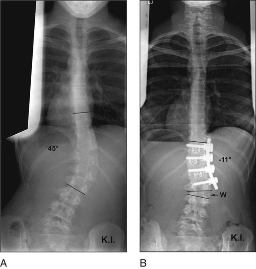
 In Figure 2A and 2B, use of the short-segment technique with the overcorrection required to balance the spine produced subjacent disk wedging.
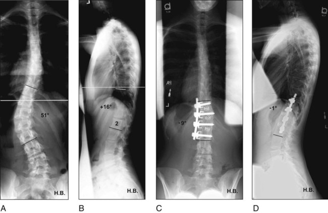
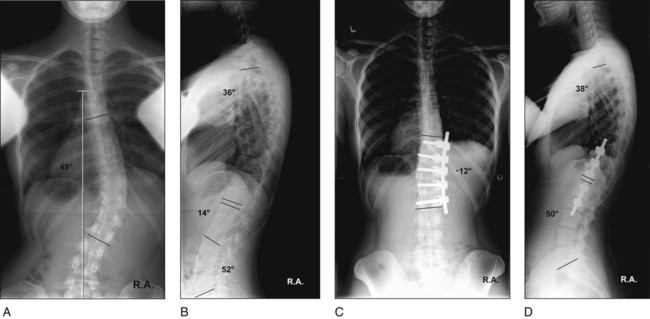
 In Figure 3A–D, the lowest end vertebra (LEV) and lowest instrumented vertebra (LIV) coincide. There is no subjacent disk wedging. Note that the preoperative thoracolumbar kyphosis has been corrected by a single rod with structural interbody graft.
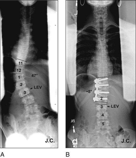
 In Figure 4A and 4B, the LIV is clearly short of the LEV, but there is only mild subjacent disk wedging.
Surgical Anatomy
 Figure 7 shows the anatomic considerations for the chest and abdominal wall.
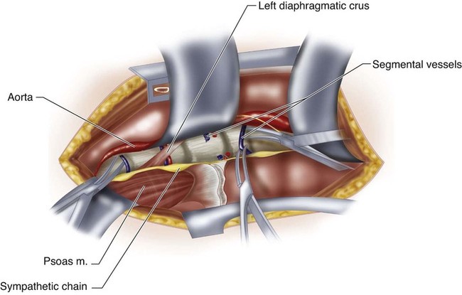
 In this left-sided approach the aorta will lie anterior to the vertebral column (Fig. 8). The left diaphragmatic crus inserts on the first and second lumbar vertebral body and may shield the segmental vessels. The sympathetic chain lies over the vertebral column just anterior to the psoas.
Positioning
 Proper positioning facilitates the exposure and can aid in the deformity correction.
 Either a conventional or flat radiolucent table may be used.
Portals/Exposures
 Rib resection permits a reliable chest entry and provides autogenous bone graft. The appropriate rib should be choosen based on the levels to be exposed.
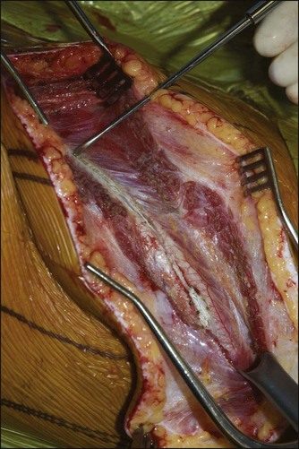
 An incision is made directly over the midpoint of the appropriate rib, extending proximally to the midaxillary line and distally as needed. The anterior border of the latissimus dorsi is developed and the dissection is taken beneath this structure (Fig. 10). In general, the incision will extend to the level of the umbilicus for exposures to the third lumbar vertebra.
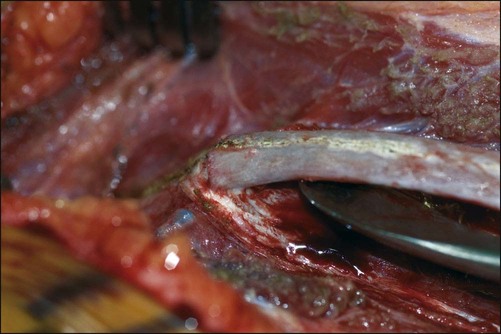
 The rib periosteum is incised and the rib exposed in a subperiosteal manner (Fig. 11). The muscle fiber direction makes it easier to dissect posterior to anterior over the superior border, and anterior to posterior over the inferior border, where care is taken to avoid the neurovascular bundle.
 The anterior rib is separated at its costal cartilage junction and then resected posteriorly while avoiding injury to the neurovascular bundle (Fig. 12).
Related posts:
 4: Open Reduction and Internal Fixation of Displaced Medial Epicondyle Fracture Using a Screw and Washer
29: Epiphysiodesis of the Distal Femur/Proximal Tibia-Fibula
32: Patellar Instability: Lateral Release and Medial Plication
31: Discoid Lateral Meniscus
39: Open Reduction and Internal Fixation of Tibial Tubercle Fractures
59: Posterior Instrumented Reduction and Fusion for Spondylolisthesis
4: Open Reduction and Internal Fixation of Displaced Medial Epicondyle Fracture Using a Screw and Washer
29: Epiphysiodesis of the Distal Femur/Proximal Tibia-Fibula
32: Patellar Instability: Lateral Release and Medial Plication
31: Discoid Lateral Meniscus
39: Open Reduction and Internal Fixation of Tibial Tubercle Fractures
59: Posterior Instrumented Reduction and Fusion for Spondylolisthesis
![]()
Stay updated, free articles. Join our Telegram channel

Full access? Get Clinical Tree


58: Anterior Spinal Instrumentation and Fusion for Lumbar and Thoracolumbar Idiopathic Scoliosis


