AP view
Lateral view
Skyline view
Implant size, positioning, and alignment (coronal)
++
Implant size, positioning, and alignment (sagittal)
+++
Implant size, positioning, and alignment (patella)
++
++
Joint line
++
++
Patella tracking
++
Patella height
+
+++
Loosening – femoral component
+
Loosening – tibial component
++
Anterior and posterior offset
+++
PE wear
+++
++
First-line radiographic evaluation of painful total knee replacement should always consist of weight-bearing anteroposterior, lateral, and patella skyline radiographs.
28.1 Anteroposterior Radiographs
Anteroposterior radiographs should be scrutinized for gross limb alignment, component sizing, and positioning. Implant loosening in a later stage as well as failure of the TKR might also be identified (Fig. 28.1). In addition, radiographs give information on periprosthetic radiolucencies representing osteolyses, fractures, excessive polyethylene wear, or heterotopic ossifications (Fig. 28.2).
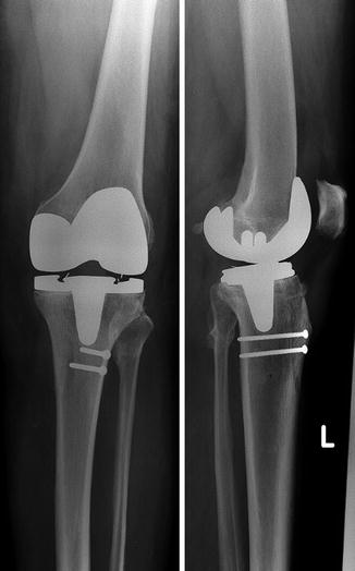
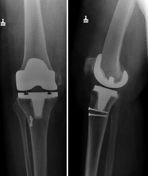

Fig. 28.1
Aseptic loosening of tibial TKR shown by radiolucent line below the tibial component

Fig. 28.2
Avulsion of the medial epicondyle as insertion of medial collateral ligament in a patient after meniscal-bearing cruciate retaining TKR
Anteroposterior radiographs give information on a variety of pathologies such as gross limb alignment, component over- or undersizing, frank malpositioning, loosening, fractures, excessive polyethylene wear, or heterotopic ossifications.
In early failure of TKR, unambiguous component malpositioning may be one of the most important pathologies to be detected on conventional radiographs. Component alignment in the coronal plane has been considered to be the most important factor in determining long-term survival of TKR [1]. Although we should be aware that the optimal method of TKR component position is by 3D CT, component position analysis on radiographs should receive special attention, as it is more commonly available [2]. In the coronal plane, the position of the tibial and femoral TKR components is evaluated in relation to the anatomical shaft axes of femur and tibia, respectively. It is usually depicted as lateral distal femoral angle (LDFA) and medial proximal tibial angle (MPTA) (Fig. 28.3a, b). In general, the femoral component is placed in 6° of valgus, whereas on the tibial side a perpendicular position is pursued. However, standard reference values and variability of these angles are under ongoing discussions. The position is dependent on the specific implant and preexisting individual patient’s anatomy [3–6]. For a proper analysis of a painful TKR, meticulous evaluation of the preoperative radiographs is also essential (Fig. 28.4).
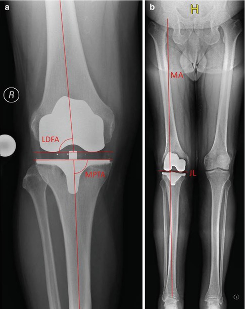
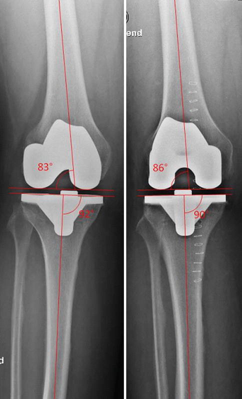

Fig. 28.3
Alignment in the coronal plane can be evaluated on (a) AP view or (b) long-leg standing view. The lateral distal femoral angle (LDFA) should be close to 84° correlating to a physiological valgus of 6°. The medial proximal tibia angle (MDTA) is aimed at 90°. The mechanical axis (MA) is the connection between hip and ankle centers. With proper restoration of the axis it should also run through the center of the knee joint

Fig. 28.4
Same patient and same TKR. Measurement of anatomical knee axis is dependent on the projection of radiograph
Although we should be aware that the optimal method of TKR component position analysis is 3D CT, component position analysis on radiographs should receive special attention, as it is more commonly available.
The rotational position of the femoral and tibial TKR components can be best assessed on 3D reconstructed CT images. Kanekasu et al. [7] proposed a method to determine femoral component rotation on an axial view of the distal femur. This radiograph is taken in 90° of flexion. The angle measured between the transepicondylar axis and the posterior condylar axis showed an acceptable correlation with the rotational position analyzed on CT scans. However, tibial rotation cannot be assessed on these radiographs.
The assessment of the joint line height helps to understand the kinematics of the knee. The joint line can be approximated on the basis of the fibular head, the femoral epicondyles, or the superior pole of the patella in relation to the superior aspect of the trochlear groove. Again, available preoperative radiographs or radiographs of the native contralateral knee help to determine the anatomical location of the joint line [8] (Fig. 28.5).
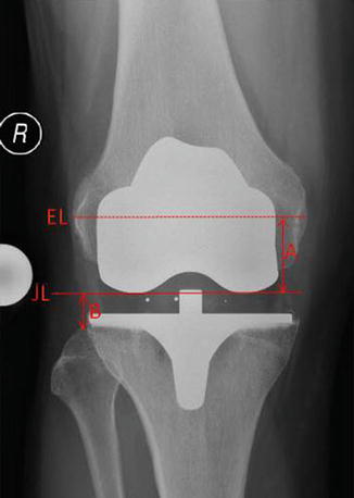

Fig. 28.5
Determination of joint line height: A in relation to the epicondylar line of the femur and B in relation to the fibular head
The joint line height can be approximated on the basis of the fibular head, the femoral epicondyles, or the superior pole of the patella in relation to the superior aspect of the trochlear groove.
Sizing and positioning of the TKR components in the mediolateral dimension can be assessed more easily for the tibial component than for the femoral one. A medial overhang of the tibial component is usually more acceptable than on the lateral side. On the other hand, if the implant size is too small or the TKR component is not supported by cortical bone, it might be prone to subsidence (Fig. 28.6). This risk is multiplied if a medially undersized tibial TKR component is accompanied by varus malalignment.
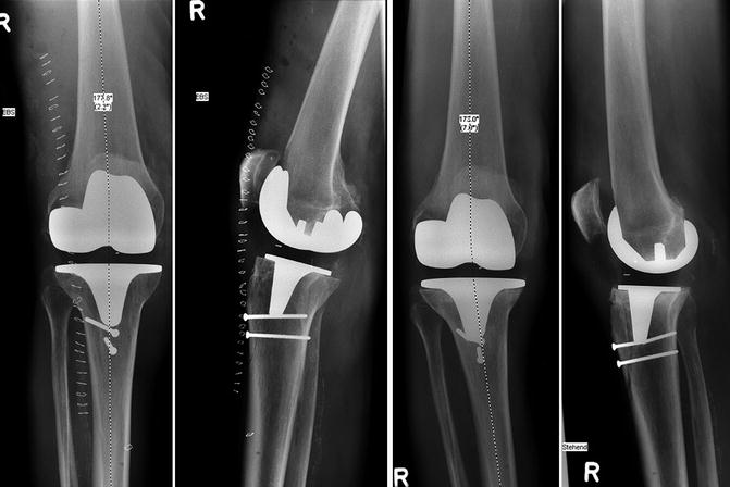

Fig. 28.6
Subsidence of the tibial TKR component into varus position in a patient who underwent a cruciate retaining TKR
Mediolateral over- and undersizing of TKR components can be assessed on anterior-posterior radiographs.
Focal periprosthetic osteolysis is usually attributed to polyethylene wear particles but can also be found in cases of infection. The most prominent signs are radiolucent lines. Osteolytic lesions usually develop adjacent to the cement-bone interface in cemented components or implant-bone interface in cementless fixation. Depending on their size and progression, they destabilize the implant and may result in considerable loss of periprosthetic bone.
The presence, localization, and extent of periprosthetic bone loss guide the strategy for revision surgery and therefore have to be carefully evaluated. The most widely accepted classification of periprosthetic bone loss is that of the Anderson Orthopaedic Research Institute (AORI), where bone loss is categorized in three groups for femur and tibia, respectively [9] (Fig. 28.7):
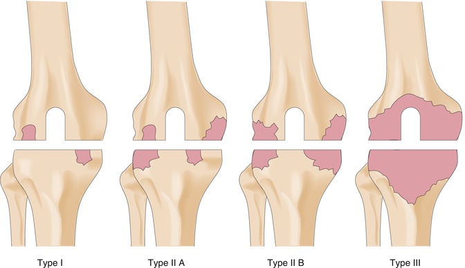

Fig. 28.7
Classification of femoral and tibial bone after TKR according to Anderson Orthopaedic Research Institute (AORI)
Type 1 defect (intact metaphyseal bone): Minor bone defects not compromising the stability of a revision TKR component.
Type 2 defect (damaged metaphyseal bone): Loss of cancellous bone in the metaphyseal segment, requiring an area of cement fill, augments, or bone graft with the revision surgery to restore a reasonable joint line level. Type 2 bone defects can occur in one femoral condyle or tibial plateau (2A) or in both (2B).
Type 3 defect (deficient metaphyseal segment): Bone loss that comprises a major portion of femoral condyles or tibial plateau. These defects are occasionally associated with collateral or patellar ligament detachment and usually require long-stemmed revision implants plus bone grafting or a custom or hinged component for the revision surgery.
Gross instability can also be seen on weight-bearing radiographs. However, for more subtle cases, please see Chap. 32.
28.2 Long-Leg Standing View
For adequate evaluation of the mechanical alignment, a long-leg view is recommended. It has been shown that femoral and tibial TKR component positioning in the coronal plane can be analyzed on a knee-only radiograph with comparable accuracy as on long-leg views, but evaluation of the mechanical axis is limited to a long-leg radiograph [10] (Fig. 28.5).
Stay updated, free articles. Join our Telegram channel

Full access? Get Clinical Tree


