Fig. 39.1
The Verso®—stemless metaphyseal reverse prosthesis
Cementless Fixation
The triple-tapered 3 thin fins of the humeral shell component combined with bone impaction technique provides immediate press fit fixation to the humeral metaphysis with further biological fixation to the porous titanium and hydroxyapatite coating (Fig. 39.2).
Fig. 39.2
Metaphyseal fixation with three fin implant and bone graft impaction
The glenoid baseplate has a tapered central titanium screw fixation with hydroxyapatite coating. The baseplate has 6 screw holes and enables the use of 2 anti-rotation screws superiorly and inferiorly. In case of fracture or deficient glenoid bone, these can be used for osteosynthesis as well (Fig. 39.3).
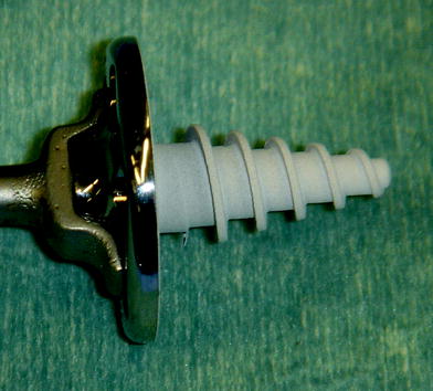
Fig. 39.3
The Verso® central tapered screw glenoid baseplate
This glenoid baseplate structure proved to provide the best fixation in a study comparing 6 different reverse shoulder designs at the Imperial College London [1].
Avoiding Glenoid Notching
Asymmetric polyethylene wear has been observed on most retrieved humeral Delta cups [2] (Fig. 39.4a) due to impingement of the humeral cup on the scapular neck. This is a cause for concern, especially if the notch is more extensive than what can be explained by impingement alone. The latter may be the initiating factor, with further osteolysis being triggered by polyethylene particles [2]. Favard et al. [3] have noted a negative effect of radiographic scapular notching on the clinical outcome: if the notch is large (extending beyond the inferior screw), the Constant score was significantly lower and the risk for loosening was high in their series.
Fig. 39.4
a Retrieved eroded humeral liner of Grammont-type prosthesis (Delta 3) at revision surgery. b The Verso® 10° angled dialable liner
It seems that medialising the center of rotation to the level of the glenoid surface and orienting the humeral cup almost horizontally have been biomechanical solutions found by Grammont to avoid excessive forces on the glenoid component and improve the power of the deltoid. However, the consequence is scapular notching and polyethylene wear.
To minimize these serious problem of glenoid notching, the Verso shoulder was designed with 3-mm lateral offset of the center of rotation outside the scapula without increasing the risk of glenoid loosening. The humeral shell is oriented with an inclination of 155°, but with the 10° angled rim dialable humeral liner, it results in 145° with a low medial edge and system that allows optimal position of the UHMWPE liner in each patient to achieve best stability and minimizing glenoid notching. By keeping the same depth of the socket and just removing the edges of the liner, the impingement of the liner with the scapula inferiorly, and in rotations, is reduced without increasing the risk of prosthetic instability.
The shape of the Verso UHMWPE liner (Fig. 39.4b) resembles the retrieved worn out humeral Delta liner cups during revision surgery (Fig. 39.4a) [2].
The system is instrumented to aim so that the bottom edge of the glenoid head is slightly lower than the bottom edge of the glenoid bone and it is angled inferiorly at 10°–15°, thus reducing further the risk of glenoid notching.
Improved Rotational Movements
Unlike anatomic shoulders where the humeral head spins around the center of rotation within the humeral head, in reverse shoulder the humerus hinges around the center of rotation in the center of the glenoid sphere [4].
With the Verso, rotational movements have been improved substantially compared with the stemmed Grammont type of prostheses with insertion of the humeral shell in 30° of retroversion and the use of the dialable 10° angle UHMWPE liners (Fig. 39.5a–d). Removing the redundant edges of the liner obliquely reduces the impingement of the liner with the scapula in rotations without increasing the risk of prosthetic instability (Fig. 39.6).
Fig. 39.5
a–d ROM after Verso TSA: a Postop elevation. b Postop ER. c Postop IR. d Postop X rays
Fig. 39.6
Anatomic versus reverse TSA—hinging versus spinning
Versatility and Adaptability
The definitive UHMWPE liner can be dialed into the best position and the humeral version adjusted even after the definitive humeral metal implant has been implanted (Fig. 39.7).
Fig. 39.7
The Verso® definitive UHMWPE humeral liner can be dialed into the best position and adjust the humeral version even after the definitive humeral metal implant has been implanted
This simple, yet sophisticated and versatile feature, allowing minor adjustments of the prosthesis even after implantation of the metal components is unique to the Verso prosthesis.
All the different sizes of liners fit all the humeral shells.
Implants for Acute Fractures, Revisions and Backup Options
Implants for acute fractures, revisions and backup options were designed as well. There is a stemmed Verso implant with low-profile shape proximally. The low profile of the proximal stemmed Verso prosthesis is ideal for fixation of the tuberosities to the titanium porous and hydroxyapatite-coated proximal implant. The stemmed humeral shell prosthesis is designed to be implanted cementless (Fig. 39.8). However, in cases of fractures, where the proximal immediate fixation is compromised, a small amount of cement can be used distally on the smooth grooved part of the stem to provide immediate rotational stability. The stemmed Verso can be used in cases of revision from stemmed shoulder replacement, anatomic or reverse.
Fig. 39.8
Stemmed implant with low-profile shape proximally for cases of fractures, nonunions and revisions, ideal for fixation of the tuberosities to the titanium- and hydroxyapatite-coated proximal implant
A salvage kit was designed for cases where the glenoid has been fractured or severely deficient and the glenoid sphere cannot be implanted. This salvage kit comprises of a “mega-head” which is 2/3rds of a sphere that can be fitted on the humeral shell as “mega hemiarthroplasty.” This lateralises the center of rotation and tensions the deltoid muscle, and therefore, hopefully, improves its function.
All options remain open for future surgery if deemed necessary as bone stock is preserved. All the liners, glenoid heads, baseplates and humeral shells are modular and interchangeable.
Simple prosthesis and surgical technique—“Simplicity is the ultimate sophistication” (Leonardo da Vinci)
We have tried to keep the prosthesis and the surgical technique as simple as possible, yet very versatile and adaptable. The simpler the procedure, the fewer places for errors.
Hasan and Matsen [6] found that most shoulder replacements in USA are performed by surgeons (75 % of the surgeons) performing only one or two shoulder replacements a year. These findings suggest the need for simple systems and surgical techniques and robust educational programs to minimize the potential adverse effects of low surgeon volume for the patients undergoing these procedures.
The Verso system has only two instrument boxes (with one tray layer of trials). The surgical technique kept simple and intuitive, yet with maximal adaptability.
Surgical Technique
Radiographic preoperative planning and templating are recommended for assessing implant sizes.
Surgical Approach
The procedure can be performed using the anterosuperior (Neviaser–Mackenzie) approach [7] or the deltopectoral approach. The author prefers the anterosuperior (Neviaser–Mackenzie) approach.
Humeral Preparation
Insertion of a humeral intramedullary guide is performed with the entry point anterior–superior to the greater tuberosity and posterior of the bicipital groove. The humeral resection guide is placed over the intramedullary guide, seated onto the humeral head and secured using the thumb screw.
The version alignment rod is attached to the intramedullary guide and aligned with the forearm to provide 30° of retroversion. A standard oscillating saw blade is placed in the slot of the humeral resection guide, and the first part of the resection is made. The cutting jig, along with the intramedullary guide and version alignment rod, is removed, and the resection of the humeral head is completed. About 20 mm of the humeral head should be removed (Fig. 39.9). If needed, according to the surgeon preplanning or intraoperative decision, an additional 5 mm of the humeral head can be resected by placing the oscillating saw against the inferior aspect of the resection guide.
Fig. 39.9
Humeral cut
The proximal humerus is now prepared to receive the humeral shell punch. The largest size of humeral punch which sits within the cortical bone should be selected. This can be determined by templating preoperatively or by intraoperative assessment. The humeral punch is directed into the hole previously made with the intramedullary guide and is positioned centrally within the cancellous bone (Fig. 39.10). The humeral punch is impacted using the humeral inserter/extractor until the fins and spherical underside of the punch are within the bone. If the punch will not seat fully, at that stage the pressure of the forked retractor during the glenoid preparation will aid its fixation into the humerus. The spherical undersurface of the humeral component is the same for all sizes. The humeral inserter/extractor is detached, leaving the punch in situ with the black cover on top as a protector during the glenoid preparation.
Fig. 39.10
Humeral punch
Glenoid Preparation
While the glenoid is being prepared, the proximal humerus is depressed. Initially, a bone spike is used to push the humerus down and assist in performing a thorough release of the capsule and labrum around the glenoid. The forked retractor is then introduced and used to push the humerus down allowing good “en face” access to the glenoid. The constant pressure of the forked retractor on the humeral shell while preparing the glenoid further impacts the cancellous bone of the proximal humerus under the shell and creates good bone impaction with gentle continuous pressure (Fig. 39.11). The instruments for glenoid preparation are laid out in the tray in their natural sequence of use from left to right.
Fig. 39.11
Lateral view—humeral shell impaction with the forked retractor while working on glenoid preparation
Drilling Central Drill Hole
Freehand drilling or using aiming guide:
Using the diathermy probe, a circle is drawn in the lower part of the glenoid. A horizontal and vertical line that crosses the center of the circle is drawn. The drill bit should be aimed at the center of the circle (the crossing of the two lines) aimed cephalad 10°–15°. It is good practice to introduce a bone spike anterior to the glenoid before drilling to assess the glenoid neck direction. Both cortices of the glenoid should be penetrated (Fig. 39.12). Using the aiming guide, position the alignment with the inferior border of the glenoid. Introduce a 2-mm guidewire through the central hole of the guide and into the glenoid. The direction of the guidewire should be cephalad 10°–15°. Once the surgeon is happy with the position of the guidewire, drill over the guidewire with a 5-mm cannulated drill bit to create the central drill hole (Fig. 39.13).
 Intact Rotator Cuff
Origins of Reverse Shoulder Arthroplasty and Common Misconceptions
1 History of Reverse Shoulder Arthroplasty
6 Preoperative Work-up and Surgical Approaches for Reverse Shoulder Arthroplasty
23 Debate: Patient-Specific Instrumentation Is Necessary versus It Is Not Necessary in All Cases
28 The Use of Convertible Glenoid Component Makes Revision to Reverse Total Shoulder Arthroplasty Easier
Intact Rotator Cuff
Origins of Reverse Shoulder Arthroplasty and Common Misconceptions
1 History of Reverse Shoulder Arthroplasty
6 Preoperative Work-up and Surgical Approaches for Reverse Shoulder Arthroplasty
23 Debate: Patient-Specific Instrumentation Is Necessary versus It Is Not Necessary in All Cases
28 The Use of Convertible Glenoid Component Makes Revision to Reverse Total Shoulder Arthroplasty Easier


Related posts:
Intact Rotator Cuff
Origins of Reverse Shoulder Arthroplasty and Common Misconceptions
1 History of Reverse Shoulder Arthroplasty
6 Preoperative Work-up and Surgical Approaches for Reverse Shoulder Arthroplasty
23 Debate: Patient-Specific Instrumentation Is Necessary versus It Is Not Necessary in All Cases
28 The Use of Convertible Glenoid Component Makes Revision to Reverse Total Shoulder Arthroplasty Easier
Stay updated, free articles. Join our Telegram channel
Full access? Get Clinical Tree
