Transfemoral Prostheses
Richard Psonak
Learning Objectives
On completion of this chapter, the reader will be able to do the following:
Advances in technology
Advances in technology, materials, and prosthetic components have had a considerable positive impact on the quality of life of individuals with transfemoral amputation. In the past, ambulation wearing a transfemoral prosthesis was labored and often painful. Only the most physically fit individuals attempted to run with their prostheses. Now socket designs better approximate anatomy of the lower limb, suspension systems enhance and maintain intimate residual limb contact within the socket, and dynamic prosthetic feet and knee components offer improved, energy-efficient function. The result has been a significant improvement in quality of gait, allowing more people with transfemoral amputation to walk comfortably and naturally with their prostheses. In addition, athletes with amputations can run in a natural “step-over-step” pattern with a higher degree of stability and comfort than previously possible.
This chapter presents information about current socket designs, suspension systems, and prosthetic knee components available for individuals with transfemoral amputation. It also provides the reader with a strategy to assess fit and alignment of a transfemoral prosthesis as well as explaining the major user-errors and prosthetic-related reasons for commonly observed gait deviations.
Prosthetic management after knee disarticulation or transfemoral amputation
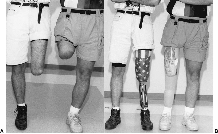
An amputation proximal to the anatomical knee joint is referred to as a transfemoral (above knee) amputation. An amputation through the center of the anatomical knee joint is known as a knee disarticulation (Figure 24-1). Individuals with knee disarticulation present with prosthetic challenges and functional advantages when compared with those with transfemoral amputation. The disarticulation residual limb tends to be long and distally bulbous, a result of the preservation of the femur and its condyles. Prosthetically, this creates a challenge in donning the prosthesis and cosmetically finishing a knee component. The bulbous distal end does, however, enhance prosthetic suspension. The normal adduction angle of the lower extremity is more likely to be preserved, and the long lever arm of the femur facilitates control of the prosthetic knee. Also, as the proximal component of a weight-bearing joint, the distal femur tolerates end-bearing pressures within the socket.
In contrast, the transfemoral residual limb varies in length, depending on how much of the femur has been retained. The shape of the residual limb is likely to be a tapered cylinder so that donning a prosthesis is less difficult. Suspension can be challenging, however, as a result of this cylindrical shape of the residual limb. The fleshiness of the transfemoral residual limb presents an opportunity for suction suspension. As the length of the residual limb decreases, socket suspension and control of the prosthetic knee (especially stance stability) become more problematic.
The successful prosthetic management of individuals who have suffered an amputation above the knee involves providing a prosthesis that is comfortable in containing the residual limb, stable during the stance phase of gait, smooth in transition to the swing phase of gait, and acceptable in appearance.1 In choosing components for an individual’s transfemoral or knee disarticulation prosthesis, the prosthetic team must consider the interrelationships among the component’s weight, function, cosmesis, comfort, and cost. Often the most functional or technologically sophisticated components are also the heaviest, most expensive, most likely to need maintenance, and least cosmetic. Because of the great variation in physical characteristics, health, and preferred activities of individuals with transfemoral amputation, no single material, component, or transfemoral design is appropriate for all persons with amputation. The preferences and needs of each individual must be considered carefully, in the context of weight, function, cosmesis, comfort, and cost, for the optimal prosthetic outcome.
Energy expenditure
An individual with a transfemoral amputation faces considerable energy expenditure when ambulating with a prosthesis (Box 24-1). The energy cost of gait increases significantly as the length of the residual limb decreases.2–6 Fisher and Gullickson report the energy cost of walking for healthy individuals (mean gait speed: 83 m/min) as 0.063 kcal/min/kg (oxygen consumption/physical effort) and 0.000764 kcal/m/kg body weight (oxygen cost/energy required to ambulate).6 Individuals with transtibial amputation walk 36% more slowly, expending 2% more kilocalories per minute and 41% more kilocalories per meter to cover a similar distance. For individuals with transfemoral amputation, gait speed is 43% slower, whereas energy cost is reflected as 5% less kilocalories per minute and 89% more kilocalories per meter. In other words, the individual ambulating on a transfemoral prosthesis walks more slowly to avoid an increase in energy consumption per minute and is dramatically less efficient in terms of energy expended over distance (per meter). This increase in energy cost is manifested as a higher rate of oxygen consumption, elevated heart rate, and notable reduction in comfortable (self-selected) walking speed.2,5,6
Because of this high energy cost, many older individuals with high-level transfemoral amputations may be limited in their ability to become functional community ambulators. Individuals who wear a prosthesis and have been diagnosed with vascular disease are often relegated to walking slowly, on flat terrain, with the assistance of a walker or cane.5,6 Elderly individuals with bilateral transfemoral amputations rarely become community ambulators with prostheses, instead choosing a wheelchair for long-distance mobility.
Transfemoral socket designs
Prior to the 1950s, prosthetists typically carved a “plug fit” socket from a block of wood, which, depending on the skill of the craftsman, was often uncomfortable and cumbersome while walking and sitting. The plug socket was crafted to contain the remnant thigh muscles, support body weight at the groin level (below the ischium), and was often open ended to eliminate distal limb contact.
Quadrilateral Socket
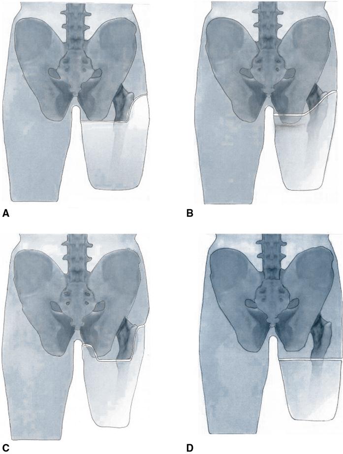
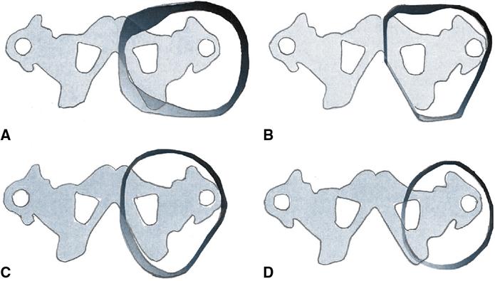
The traditional quadrilateral (quad) socket, developed at the University of California at Berkeley in the 1950s, offered a notable improvement in fit, total contact, function, and remained the socket design of choice until the mid-1980s. The quad socket, as its name implies, has four distinct walls fashioned to contain the thigh musculature. The quad socket was designed to be a complete above-the-knee prosthetic system that interfaces with the individual who wears the prosthesis. The socket’s primary functions are to provide for weight-bearing during the stance phase of gait and to allow the hip and thigh muscles to function at maximum potential during the stance phase of gait (Figure 24-2, A).1,7,8 A flat posterior shelf, the ischial seat, is the primary weight-bearing surface for the ischium and gluteal muscles. The anterior wall contours create a posterior-directed force at the anatomical Scarpa’s triangle, which is intended to stabilize the ischium on its prosthetic seat. As a result, the socket is narrower in its anterior–posterior dimension than its medial–lateral dimension (Figure 24-3, A).
Evolution of Ischial Containment Sockets
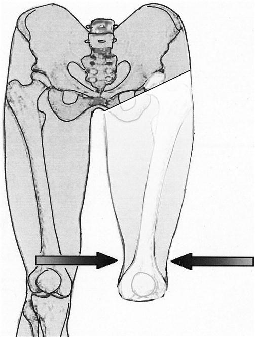
The next stage of socket designs evolved in 1970s after prosthetist Ivan Long took part in a project that evaluated radiographically the femoral alignment of the transfemoral limb within a quad socket.9 Long observed that many individuals who wear a quadrilateral socket walk with an extremely wide base and demonstrated a Trendelenburg or gluteus medius limp, causing the individual to lean to the amputated side. He also noted that in most cases the transected femur was aligned in abduction as opposed to the normal adduction angle of the sound side femur (Figure 24-4). The abnormal abduction angle of the femur was believed to be in part the result of the quad socket’s unnaturally wide medial–lateral dimension and narrow anteroposterior dimension. The wide medial–lateral dimension of the quad socket allows the socket to displace laterally during midstance, thus increasing pressure to the perineal tissues and decreasing the efficiency of the gluteus medius muscle.9,10
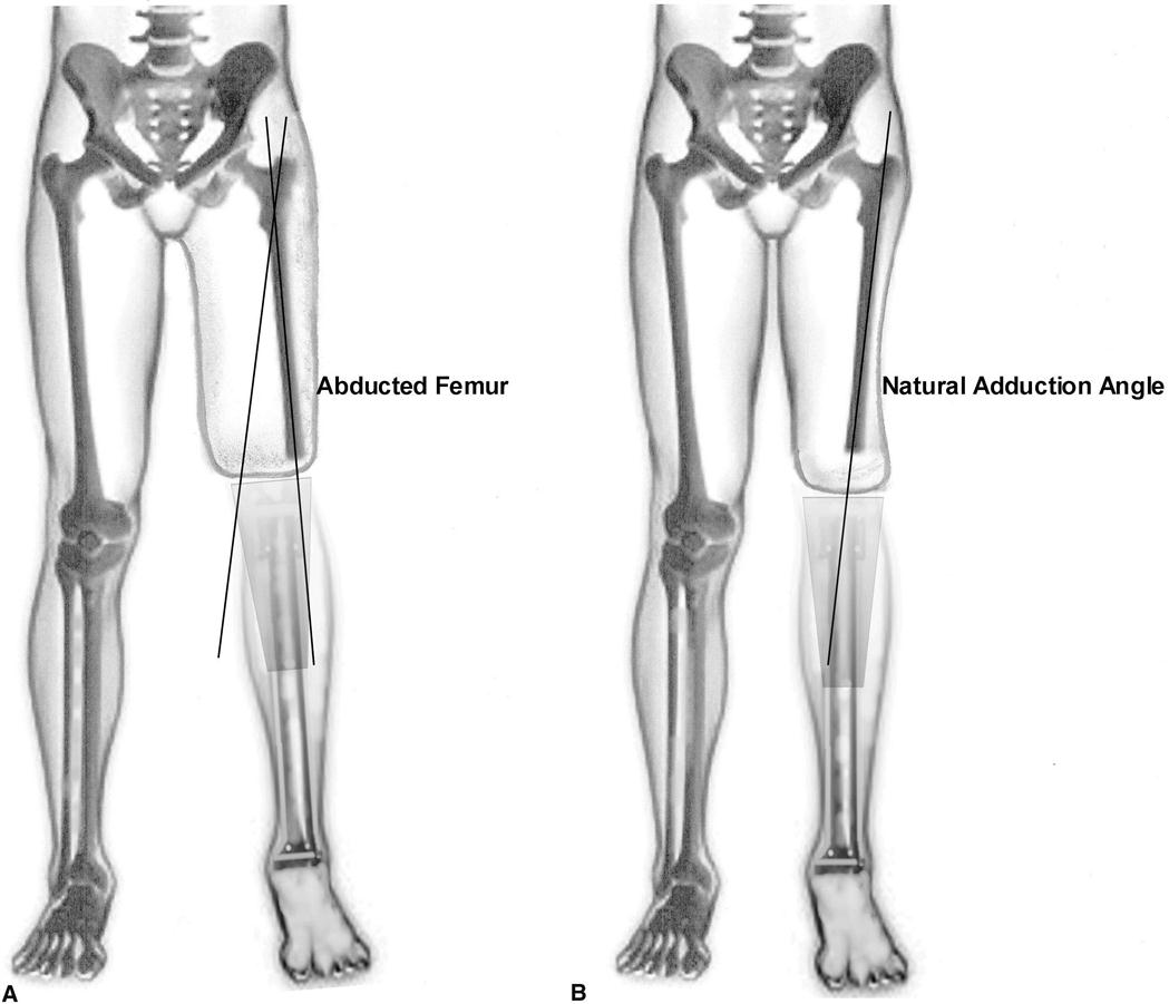
Long’s socket design was part of a frontal plane alignment procedure that became known as “Long’s Line.”9,10 Long believed that by aligning the distal femur over the center of the knee and through the center of the foot, the wearer of the prosthesis could bring their residual limb into a normal anatomical position and walk more naturally. Long narrowed the medial–lateral dimension of his socket design and increased anteroposterior dimension in an attempt to support the femur and to prevent lateral shifting of the socket during weight bearing. According to Long,9,11 an additional advantage of his design is that the wider anteroposterior dimension enhances muscle function by providing more room to accommodate muscle contraction than possible in the crowded anteroposterior dimension of the quad socket.
In the 1980s prosthetist John Sabolich expanded upon Long’s concept and developed his contoured anterior trochanteric-controlled alignment method (CAT-CAM) socket (see Figure 24-2, B).11–13 His design attempted to both maintain the femur in an adducted position and control socket rotation by containing the ischial tuberosity within the contours of the socket. Since the CAT-CAM design, a series of sockets have been developed that have become known as ischial containment or ischial-ramal containment (IRC) sockets, depending on what anatomy is contained within the socket.12,13 When comparing the IRC socket with the quad socket, the most obvious difference is the narrow medial–lateral dimension that is highly contoured around the ischial–ramal complex (see Figure 24-3, B).12
Socket Configuration Influence on Femur Position
The degree to which the prosthetic socket design can influence the position of the transected femur has been hotly disputed. Orthopedic surgeon Frank Gottschalk developed a myodesis surgical technique to ensure proper femoral adduction in a transfemoral residual limb.14 In the journal article, “Does socket configuration influence the position of the femur in above-knee amputation?,” Gottschalk and colleagues concluded that the prosthetic socket cannot provide enough lateral pressure to change the position of the femur.15 The authors indicated that proper anatomical adduction is achieved only through specific surgical techniques. Most practitioners would agree with Gottschalk when he suggests that “successful prosthetic fitting starts at the time of surgery.”14,15 However, there is also a consensus that indicates that an intimately contoured socket in optimal alignment enhances an individual’s gait, decreases energy expenditure, increases socket comfort, and improves overall function.16 Clearly more research is required to understand the relationship between alignment, socket design, and femoral adduction.
Marlo Anatomical Socket
In the late 1990s, Marlo Ortiz, an engineer-prosthetist from Mexico, developed a socket configuration that focuses on providing skeletal support along the medial ischial–ramal complex (IRC) (see Figure 24-3, C).17 The socket design became known as the MAS socket (Marlo Anatomical Socket). The MAS socket attempts to encapsulate the ischial tuberosity, as well as portions of the ramus, with a distinguishable containment buttress that is designed to maximize socket stabilization (see Figure 24-2, C). The socket features a low posterior trim line that is said to facilitate the containment of the ischial–ramal complex without interference from the gluteus maximus trim lines. The low gluteal trim lines also allow the prosthetic user to sit directly on the gluteus maximus instead of the posterior socket. External rotation at the hip is virtually unrestricted, minimizing the need for a transverse rotation unit (see Figure 24-18) proximal to the prosthetic knee joint.
Elevated Vacuum Sockets
The latest rendition of transfemoral socket designs has developed as a result of the ever expanding interest in elevated vacuum suspension, also referred to as subatmospheric suspension (see Figure 24-3, D).18 This socket design is characterized by lower trim lines (subischial) in comparison to other transfemoral socket designs, resulting in substantially increased patient comfort and range of motion (see Figure 24-2, D). The proximal socket brim has been lowered as much as two-four inches below the ischial tuberosity level on transfemoral residual limbs greater than midlength.19 By utilizing elevated negative pressure around the distal two-thirds of the residual limb, the socket no longer requires compression of the proximal residual limb anatomy to provide weight bearing and stabilization. As a result of less proximal compression, there is no longer a need for prominent flares, reliefs, and channels, thus allowing lower trim lines of the socket. The proximal roll on liner contains the soft tissue of the adductor muscles. Some have referred to this style of socket as brimless.19
Radcliffe7 suggests that, regardless of socket design, the primary goals of the transfemoral prosthesis are to achieve comfort in weight bearing, to provide a narrow base of support in standing and walking, and to accomplish as close to normal swing phase function as possible. Mak and colleagues indicate that, “For all prosthetic socket designs, the optimal load distribution should be proportional to the ability of the body to sustain such stresses.” The authors go on to summarize that, “The basic principles for socket design vary from either distributing most of the load over specific load-bearing areas or more uniformly distributing the load over the entire limb.”20
Rigid and flexible socket materials
Most transfemoral sockets are fabricated from various thermoplastic or thermosetting resin materials. A rigid socket consists of a resin-laminated or thermoformed plastic socket that is intended to have an intimate, total contact fit over the entire surface of the residual limb. The rigid socket is durable, easy to clean, and often less bulky and less expensive to produce than flexible sockets. The disadvantage, is that it more difficult to adjust the fit of a rigid socket, especially for individuals with “bony” or sensitive residual limbs.
The flexible socket is vacuum formed using any number of flexible thermoplastic materials.21,22 It is encased in a rigid frame, which provides support during weight bearing and helps to maintain socket shape. The flexible socket accommodates to change in muscle shape during contraction and can be easily modified after initial fabrication to provide relief for bony prominences. Flexible sockets may also be more comfortable to wear, especially in sitting, because there are no hard edges at the brim to impinge on the groin. Flexible sockets are especially useful if suction suspension is desired. They are, however, somewhat less durable, more bulky to wear (requiring a socket and a frame), and more expensive to produce than rigid sockets.
Transfemoral suspension systems
Keeping the prosthesis on in its optimal functional position is more challenging for individuals with transfemoral amputation than with transtibial amputation. The transfemoral residual limb is fleshy and cylindrical, lacking the bony prominences that aid in suspending the transtibial prosthesis. The weight of the transfemoral prosthesis with the addition of its knee unit creates an additional challenge for adequate suspension. Depending on the nature of the prosthetic wearer’s normal activities, a single system or a combination of several systems may be chosen.
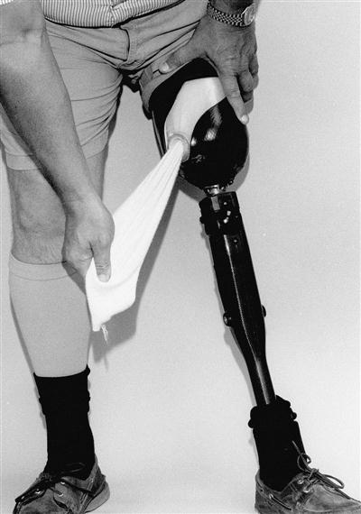
Traditional Pull-in Suction Suspension
Traditional pull-in suction suspension uses negative air pressure, skin-to-socket contact, and muscle tension to hold the socket onto the limb (Figure 24-5).23 A suction prosthesis can be donned in several ways. One option uses donning sock (cotton stockinette or similar material), donning sleeve (parachute nylon or similar material), or elastic bandage to pull the residual limb down into the socket. Once the limb is well seated in the socket, the sock, sleeve, or elastic wrap is pulled through the valve housing at the distal socket, and the air expulsion valve is then screwed into place. This process requires considerable agility and balance on the part of the wearer. A second option is to add a lubricant to the skin to facilitate the residual limb sliding into the socket. The air-expulsion valve is then “burped,” by pushing or pulling the valve button, to release any trapped air.
The intimate fit required for suction suspension has several additional benefits. The wearer often reports enhanced prosthetic control and a better proprioceptive sense of the prosthesis during walking. Because an intimate fit is essential, suction suspension is inappropriate for patients with recent amputation who will continue to lose limb volume or for those with a history of fluctuating edema or unstable weight. The high shearing forces associated with donning a suction socket also may preclude its use for patients with fragile or sensitive skin, painful trigger points, significant scarring, or adhesions.
Roll-on Suspension Liners
Growing in popularity as a suspension system is the use of roll-on liners. These liners are available as an alternative to the standard suction suspension system. Roll-on liners are manufactured from various materials, including silicone, urethane, and elastomer. They are produced by several manufacturers in a variety of sizes, thicknesses, and tapers.24 Worn against the skin, roll-on liners are donned by first being turned inside-out, then rolled directly over the residual limb. The roll-on suspension liner creates a negative atmospheric pressure and somewhat adhesive bond to the skin. The liner can be used for suspension in several different ways: in a shuttle lock system, as part of a lanyard system, as a cushion liner used with an air expulsion valve, or as a vital part of an elevated vacuum socket.
Shuttle Lock Systems
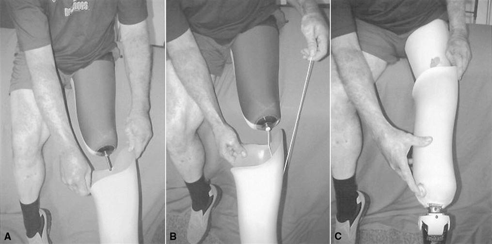
This liner is commonly called a locking liner. It is similar to the cushion liner except for a distal stabilizing matrix incorporated into the liner to prevent elongation. This liner also has an external distal cap, the center of which a serrated pin screws into and sticks out approximately 11/2 inches. The pin engages into the shuttle lock, inside the bottom of the socket, when the individual stands and pushes his or her limb down into the socket. To remove the prosthesis, the individual depresses a release button on the medial aspect of the socket that disengages the serrated pin (Figure 24-6, A).
Lanyard System
This system uses the locking liner, but instead of a locking pin screwed into the liner’s distal cap, a lanyard (strap or cord) is attached to the cap. This is routed through the distal socket to pull the residual limb into the socket (see Figure 24-6, B). The lanyard is then attached to the external lateral aspect of the socket using Velcro. Many designs maintain suspension and rotational control by providing suspension distally and stability laterally through an additional loop attached to the liner proximally (Figure 24-7). Some systems utilize a ratcheted strap much like a ski boot binding as a lateral suspension strap.
Cushion Liner with Air Expulsion Valve
This type of liner is generally referred to as a cushion liner. After the liner is donned on the residual limb, it is pushed into the socket, creating a negative pressure environment by expelling air through the expulsion valve (see Figure 24-6, C). This process is similar to the traditional skin suction socket method mentioned previously.
Elevated Vacuum
Elevated vacuum is different than suction suspension. Both methods use a difference in atmospheric pressure to suspend and secure the socket to the residual limb. Suction suspension requires a passive expulsion valve to allow air to exit from the socket, but only creates a negative pressure differential when the prosthetic limb is unweighted as when moving into swing phase. With vacuum suspension the residual limb is continuously under vacuum. A vacuum pump creates negative pressure to remove air from a sealed environment between the total surface bearing socket and a wicked-liner (see Figure 24-6, D). The vacuum created by a vacuum pump’s removal of air holds the intimately fitting liner firmly to the walls of the socket.25 This system does not depend on the limb position. An elevated vacuum of approximately 15 inches Hg between the limb liner and the socket controls volume fluctuations in the socket.26,27
Pistoning between the limb, liner, and socket is virtually eliminated within an elevated vacuum system. Individuals using vacuum-suspended prostheses report having greater proprioception and a sense that the prosthesis feels lighter when using vacuum suspension in comparison to other types of suspension.25 It has also been suggested that an elevated vacuum system maintains the volume of the limb in the socket by improving circulation within the limb, and may help to heal wounds and improve limb health.28
The major advantage of roll-on suspension is a significant reduction in the amount of friction and shear on the residual limb.29 The donning procedure is simple, and can be accomplished while seated. This suspension system has been useful for individuals with short residual limbs and those who have experienced discomfort using the traditional pull-in suction method. The disadvantages of this system include its expense and durability. Roll-on liners become worn or torn, and must be replaced two to three times a year depending on the wearer’s activity level. These types of liners may also increase skin temperature and perspiration. Some wearers have experienced rashes or other types of skin irritation as a result. Wearers who choose this type of suspension must clean the liners daily to prevent the buildup of perspiration and bacteria.30,31
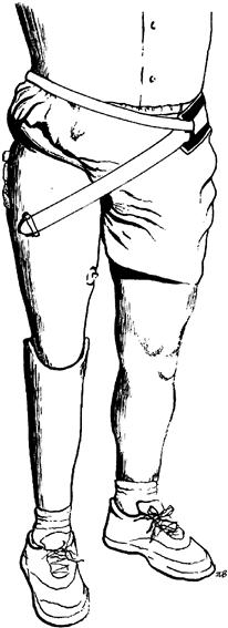
Silesian Belt Suspension
A Silesian belt is usually made from leather or lightweight webbing (Figure 24-8). It is attached to the lateral aspect of the socket, encircles the pelvis, and then runs through a loop or buckle on the anterior of the socket. The Silesian belt is most often used as an auxiliary (backup) for traditional suction suspension systems. The problem with choosing the Silesian belt as the sole means of suspension lies in its inability to control residual limb rotation within the socket. For individuals with long residual limbs who are not expected to be vigorous ambulators, the Silesian belt may provide adequate suspension.
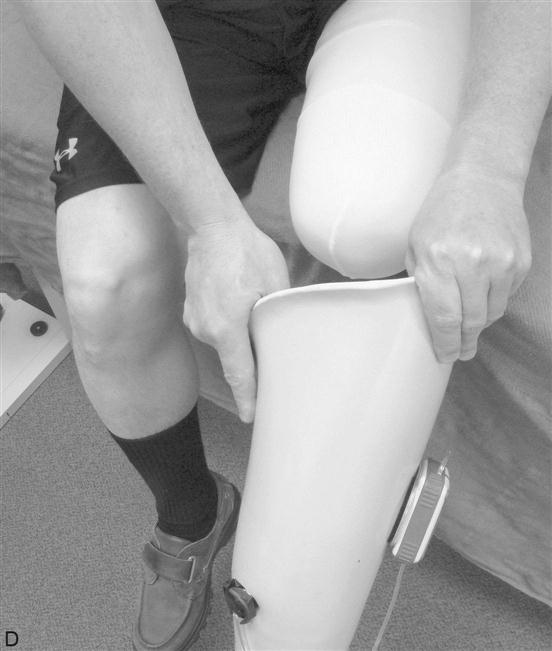
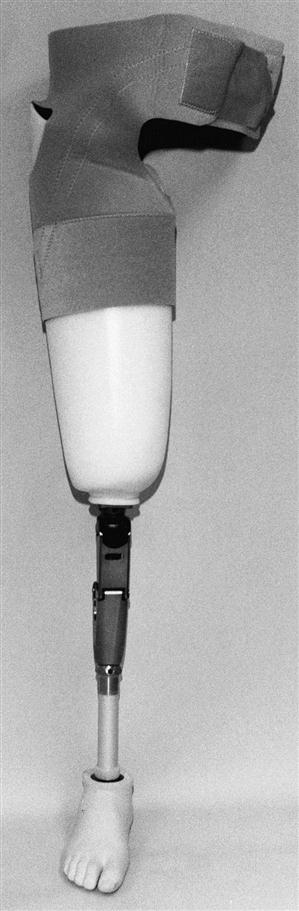
Total Elastic Suspension Belt
The total elastic suspension (TES) belt is typically made of an elastic neoprene material. The distal sleeve of the TES belt fits snugly around the proximal half of the thigh section of the transfemoral prosthesis. The neoprene belt encircles the waist and attaches in front with Velcro (Figure 24-9). The TES belt is easy to don, comfortable to wear and is an excellent auxiliary suspension system. This system is generally not recommended as a sole source of suspension for prosthetic users who are active ambulators, because like the Silesian belt, the TES belt cannot control residual limb rotation adequately within the socket. The major disadvantages of the TES system include its limited durability, especially for active ambulators, and its tendency to retain heat. It is often chosen for individuals with recent amputation whose residual limb has not yet matured to a stable size, for older patients who are unable to use the pull-in suction or roll-on liners because of upper-extremity weakness or pain, and for those with easily irritated skin or adhesions who cannot tolerate suction. It may also be used as a backup or secondary suspension system for individuals who use suction suspension when playing sports or engaging in high-activity leisure activities.
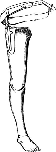
Pelvic Belt and Hip Joint
For some patients, a pelvic belt and hip joint are used as a means of suspension (Figure 24-10). Generally, the pelvic belt is made of leather and attached to the prosthesis by means of a metal hip joint. Recently, lighter-weight plastic materials have been used as an alternative to the metal joint. Whatever the material, the joint center should be positioned just superior and anterior to the anatomical greater trochanter. This system not only suspends the prosthesis but also helps to control rotation and increase medial-lateral stability of the residual limb within the socket. Traditionally, this has been the suspension of choice for those with short residual limbs. The major drawbacks of this type of suspension are its bulkiness under clothing, added weight, and tendency to be uncomfortable when sitting.
Knee Disarticulation Considerations
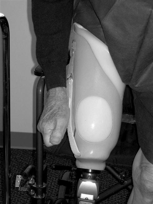
When femoral condyles are not prohibitively bulbous, roll on sleeves can be used in combination with air expulsion. Although a pin is not recommended because of space limitations, a lanyard system can be effective. This creates a positive lock that is engaged even if limb volume changes. When the femoral condyles are prominent a removable door suspension design can be used to suspend the prosthesis. This suspension uses external straps, attached to a door, which can apply variable pressure proximal to the femoral condyles locking them in place (Figure 24-11). This suspension system is similar to the medial opening door occasionally used for Symes prosthesis.
The stovepipe Pelite liner is another method of suspending a bulbous residual limb in the knee disarticulation prosthesis. This suspension method is also similar to a suspension system used for Symes amputations. This method, utilizes pads built up around the femoral condyles that are blended into the largest circumference of the liner until the limb is more cylindrical in shape (similar to a stovepipe). A slit is cut over the medial condyle area to allow the bulbous end of the residual limb to pass through the narrow section of the liner when donning.32 This system is easy to fabricate and provides good suspension and comfortable padding, especially for more bony limbs.
Prosthetic systems
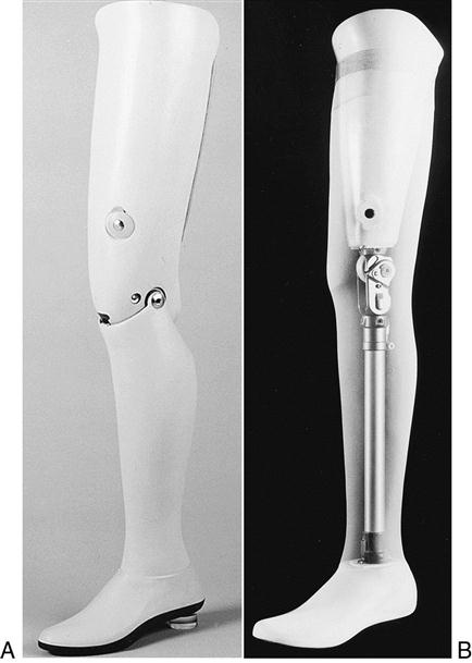
A transfemoral prosthesis can be fabricated as either an exoskeletal or endoskeletal system. The weight-bearing strength and cosmetic shape of an exoskeletal prosthesis are provided by a laminated shell that incorporates the socket, knee–shin component, and ankle block (Figure 24-12, A). This system is durable and requires little maintenance but cannot be easily realigned or adjusted. In the endoskeletal system, weight-bearing strength comes from an internal pylon that connects the knee unit to the prosthetic foot (Figure 24-12, B). The cosmetic shape of the prosthesis is provided by a soft foam cover, carved to mirror the remaining limb, which is fit over the socket, knee unit, and pylon. This foam shell is, in turn, covered by cosmetic stockings or a silicone “skin” to achieve the desired skin color. The endoskeletal system has two distinct advantages: the prosthetist is quickly able to adjust prosthetic alignment, and easily interchange or replace modular components. This is particularly helpful as new prosthetic users become more competent in controlling their knee unit or when advancing mobility leads to different functional needs (e.g., involvement in athletic activities). The durability of the foam and cosmetic coverings may be an issue for some prosthetic users, especially when work or leisure activities are physically demanding or occur in harsh environments.
Prosthetic knee units
The function of the human knee joint is difficult to replicate. Henschke Mauch, who developed hydraulic guidance systems for rockets during World War II, turned his considerable knowledge and creativity to designing a hydraulic prosthetic knee for veterans with amputations after the war.33 He commented that it was far easier to design a large rocket with a guidance system capable of maneuvering hundreds of miles than to duplicate the human knee. The anatomical knee is a modified hinge-type synovial joint. The offset axis of the knee allows rotation in addition to flexion and extension, practically making it three joints rolled into one.34 Because most prosthetic knees function in a single plane of motion, the action of the anatomical knee is difficult to fully replicate. As a result, it is more difficult for the individual who is using a transfemoral prosthesis to walk as efficiently and cosmetically as someone using a transtibial prosthesis.
Prosthetic knee mechanisms have two primary functions. First, to simulate normal gait, the prosthetic knee must smoothly flex and extend through the swing phase of gait. The speed or rate of shin advancement during swing is determined by the mechanical properties (friction or resistance) of the prosthetic knee unit. Second, the prosthetic knee must remain stable as body weight rolls forward over the prosthetic foot during the stance phase of gait. The major categories of commonly used prosthetic knee units vary with respect to how, and to what degree, they accomplish these two tasks. Various knee units are available in endoskeletal and exoskeletal versions.
Single-Axis Knee Units
The single-axis knee simulates a simple hinge and allows the prosthetic shin to swing freely in flexion and extension. Stance-phase knee stability is achieved by a combination of positioning of the knee unit with respect to the weight line (alignment) and muscular control (activity of hip extensors). This knee is lightweight, durable, and low maintenance, but because of its unrestricted movement, it has no inherent mechanical stability. For this reason, it is not appropriate for individuals with relatively short residual limbs who lack the mechanical advantage of a long femoral lever for muscular control of the knee unit or for those whose stability is compromised for other reasons. Although the rate of advancement of the shin during swing phase (determined by the friction setting of the knee) can be individualized, cadence responsiveness is minimal once the resistance has been set. The shin of the prosthesis will swing forward at the same rate, regardless of gait speed. As a result, an audible terminal impact often occurs as the knee reaches full extension. To run with a single-axis knee, the individual must use a skipping pattern on the intact stance limb while waiting for the prosthesis to complete the swing phase and begin the initial heel contact. The single-axis knee is primarily for patients with long residual limbs who can voluntarily stabilize the knee through active hip extension against the posterior wall of the prosthesis.
Polycentric Knee Units
The single-axis knee has a fixed center of rotation, while the polycentric knee has a moving center of rotation. Like the human knee, the polycentric knee rotates around more than one axis through a four or more bar linkage system (Figure 24-13). A proximal and posterior location of the instantaneous center of rotation promotes knee stability during the stance phase of gait.35
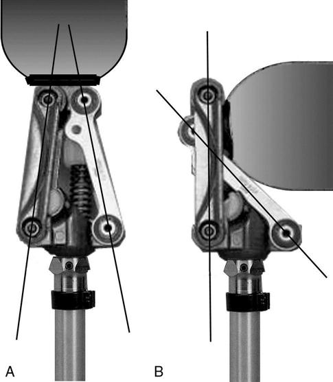
As the knee unit flexes during swing phase, the polycentric axis of motion leads to relative “shortening” of the distal prosthesis (shin and foot components), which enhances toe clearance throughout swing phase.36 It is especially helpful for individuals with long residual limbs or knee disarticulation because the changing center of rotation allows the shin to tuck under the thigh when sitting, resulting in a more natural and cosmetic appearance of thigh and shin lengths. The polycentric knee unit’s inherent stance phase stability also makes it an option for individuals who have short residual limbs or significant weakness of hip extensors. The major disadvantage of the polycentric knee, with its multiple mechanical joints, is its durability.
Weight-Activated Stance Control Knee Units
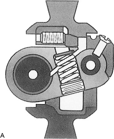
The stance control knee has a braking mechanism that is activated when weight is applied through the knee during the stance phase of gait (Figure 24-14). The intent of the braking mechanism is to prevent (or at least reduce) unwanted knee flexion during stance. The sensitivity of the braking mechanism can be adjusted to match the individual’s level of activity and ability to control the knee voluntarily. If initial contact is made when the knee is not completely extended, as when walking on uneven ground, the braking mechanism provides additional mechanical stability to keep the knee from rapidly buckling. During swing phase, the weight- activated stance control knee unit functions like a single-axis knee and has similar disadvantages. Advancement of the prosthetic shin occurs at the same rate regardless of changes in gait speed; minimal cadence responsiveness is present. This type of knee unit is most often prescribed for individuals who have recently undergone amputation, and who have short residual limbs or weakness of hip extensors and would otherwise have difficulty in actively stabilizing their prosthetic knees.
Manual Locking Knee Units
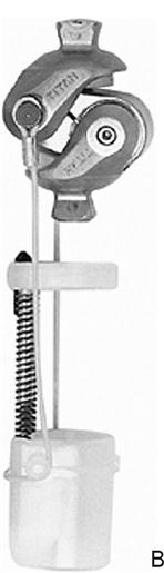
For patients who must rely on mechanical stability in stance, the knee of choice is often a manual locking knee. This unit is basically a single-axis knee with the addition of a locking pin mechanism (Figure 24-15). The pin automatically locks with a distinctive click when the knee is fully extended. Individuals who use a manual locking knee unit walk with their prosthetic knees locked in extension. Although a locked knee provides maximum mechanical stability in stance, it also significantly compromises mobility and toe clearance in swing. The prosthesis is often fit to be slightly shorter than the sound side limb to facilitate toe clearance during swing of the prosthesis. The prosthetic wearer can manually unlock the knee by manipulating a pulley or lever system attached to the outside of the socket. This unit is often used in the initial training prosthesis for patients when balance, endurance, or cooperation may be problematic.
< div class='tao-gold-member'>


Stay updated, free articles. Join our Telegram channel

Full access? Get Clinical Tree


