Topographic and Arthroscopic Anatomy of The Ankle
Sami Abdulmassih
Fernando Pena
Annunziato Amendola
The first efforts at arthroscopic intervention, dating back to 1918, were made by Dr. K. Takagi at the University of Japan. Considering the technologic limitations at that time, the knee joint was the focus of interest. Burman, in 1931, in New York, reported on arthroscopy of 100 knees, 25 shoulders, 20 hips, 15 elbows, 6 wrists, and 3 ankles (1). He stated that the ankle “is not suitable for arthroscopy.” The congruency of the ankle joint and the diameter of the cannula (4 mm) seemed to be the most limiting factors. Later, M. Watanabe, a protégé of Dr. K. Takagi, developed new arthroscopes and expanded arthroscopy to joints other than the knee. In 1977, Dr. Hiroshi Ikeuchi, a student of Dr. Watanabe, presented one of the first series on ankle arthroscopy with clear examples of intra-articular pathology (2). As described in Guhl’s book (2), this presentation inspired Guhl and others to pursue further interest in this field of arthroscopy. More recently, several authors, among them Ewing, Ferkel, and Guhl, have popularized arthroscopy of the ankle joint (2, 3, 4 and 5). Although it is still an evolving area of arthroscopic surgery, ankle arthroscopy has demonstrated high rates of success and minimal complications with proper technique and indications.
Complications associated with ankle arthroscopy can be avoided or significantly decreased by a solid knowledge and familiarity with the anatomy of the ankle joint and the structures crossing along this joint. Feiwell and Frey (6), as well as Sitler et al. (5), described in detail the relationship of structures at risk with placement of standard ankle portals. These and other reports added to the improved visualization and access to the ankle joint, allowing an expansion in indications for ankle arthroscopy.
This chapter reviews the normal topographic anatomy, vital structures, and arthroscopic anatomy of the ankle joint.
TOPOGRAPHIC ANATOMY
The ankle joint consists of the distal tibia, the fibula, and the talus. The configuration of bony anatomy makes the ankle joint a very congruent joint with limited access if the soft tissue and bony structures are respected. Therefore, ankle arthroscopy represents a challenge to achieve full visualization and working access to the joint, without creating any iatrogenic injury.
The medial malleolus extends approximately 1 cm distal to the joint line. The posterior tibialis tendon lies on the posterior half of the malleolus; posterior to it, the tibial nerve, the tibial artery, and the flexor hallucis longus (FHL) tendon are found and protected. Anterior to the medial malleolus lie the most distal and fine branches of the saphenous nerve, which are posterior and medial to the great saphenous vein. These branches may extend as far distally as the first metatarsophalangeal joint, where they anastomose with the most medial branches of the superficial peroneal nerve. The “soft spot” of the ankle joint is located between the anterior tibialis tendon and the medial malleolus. This represents a safe area to place an anteromedial portal; however, the portal should be placed as close as possible to the medial aspect of the anterior tibialis tendon, in order to avoid the saphenous nerve and vein as well as the medial malleolus (3) (Fig. 85.1).
Anteriorly, the thin subcutaneous tissue allows easy palpation of the anterior compartment structures. From medial to lateral, there are the anterior tibialis tendon, the extensor hallucis longus tendon, the anterior tibial artery and vein, the deep peroneal nerve, and the extensor digitorum longus tendon. Previous publications described the anterocentral portal, which provides a broad anterior visualization of the ankle joint (4, 7, 8). More recent reports (6, 9) have pointed out the risk of injuring the anterior structures with the use of this portal. In addition, adequate access through anteromedial and anterolateral portals has made the anterocentral portal unnecessary for full visualization (Fig. 85.2).
The superficial peroneal nerve may be found along the lateral half of the anterior aspect of the ankle. Plantar flexing and inverting the foot facilitate visualization of this nerve under the skin in many cases. Because injury to this nerve is the most common complication when using the anterolateral
portal, it is important to discuss the anatomy in detail (2, 4). Although multiple anatomic variations have been described, the nerve becomes subcutaneous approximately 10.5 cm proximal to the tip of the fibula in 91% of specimens (10). At this level, it is most likely to be found along the anterior margin of the fibula. From that point, it branches into the medial terminal branch and the intermediate dorsal cutaneous branch. In 92% of specimens, this division occurs 6.5 cm proximal to the tip of the fibula (11). The medial terminal branch crosses the ankle joint line along the anterior middle third, adjacent to the extensor hallucis longus tendon. More distally, it trifurcates into three final branches to innervate the dorsal aspect of the medial half of the foot. The most lateral branch, the intermediate dorsal cutaneous branch, crosses the ankle joint subcutaneously at the level of the fourth and fifth extensor digitorum longus tendons, and from there it aims for the third intermetatarsal space (Fig. 85.3). This is the branch at risk when an anterolateral portal is created. More distally, it may have some anastomosis with the most dorsal branches of the sural nerve. The medial and the intermediate branches provide sensation to most of the dorsal skin of the foot. The deep peroneal nerve innervates the dorsal aspect of the first web space.
portal, it is important to discuss the anatomy in detail (2, 4). Although multiple anatomic variations have been described, the nerve becomes subcutaneous approximately 10.5 cm proximal to the tip of the fibula in 91% of specimens (10). At this level, it is most likely to be found along the anterior margin of the fibula. From that point, it branches into the medial terminal branch and the intermediate dorsal cutaneous branch. In 92% of specimens, this division occurs 6.5 cm proximal to the tip of the fibula (11). The medial terminal branch crosses the ankle joint line along the anterior middle third, adjacent to the extensor hallucis longus tendon. More distally, it trifurcates into three final branches to innervate the dorsal aspect of the medial half of the foot. The most lateral branch, the intermediate dorsal cutaneous branch, crosses the ankle joint subcutaneously at the level of the fourth and fifth extensor digitorum longus tendons, and from there it aims for the third intermetatarsal space (Fig. 85.3). This is the branch at risk when an anterolateral portal is created. More distally, it may have some anastomosis with the most dorsal branches of the sural nerve. The medial and the intermediate branches provide sensation to most of the dorsal skin of the foot. The deep peroneal nerve innervates the dorsal aspect of the first web space.
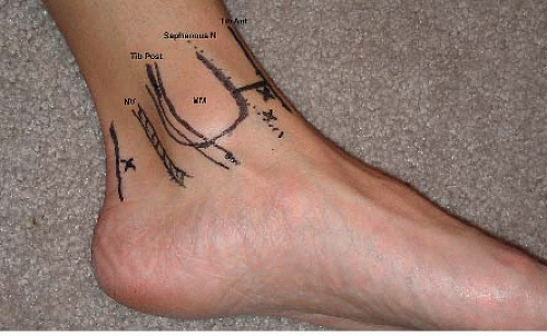 FIGURE 85.1. Medial aspect of the ankle with location of the anteromedial, accessory me dial, and posteromedial portals. MM, medial malleolus; NV, neurovascular bundle; N, nerve. |
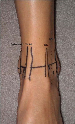 FIGURE 85.2. Anterior aspect of the ankle with location of the accessory medial, anteromedial, anterolateral, and accessory lateral portals. SPN, superficial peroneal nerve; MM, medial malleolus; LM, lateral malleolus; N, nerve; EDL, extonsor digitorum longus. |
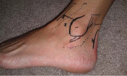 FIGURE 85.3. Lateral aspect of the ankle with location of the anterolateral, accessory lateral, and posterolateral portals. EDL, extensor digitorum longus; SPN, superficial peroneal nerve; LM, lateral malleolus; T, tendon; N, nerve. |
The lateral malleolus extends more posteriorly and distally than its medial counterpart. The tip of the malleolus is, on average, 2 cm distal to the joint line and 1 cm posterior to the medial malleolus. Posterior to the fibula, the peroneal tendons curve inferiorly, and the sural nerve may be found more posteriorly. The sural nerve is located an average of 1 to 1.5 cm distal and 1.5 to 2 cm posterior to the tip of the fibula. It travels anteriorly and laterally to the lesser saphenous vein, which may be found in the immediate vicinity of the nerve. As mentioned previously, at the level of the tuberosity of the fifth metatarsal, it divides into its terminal medial and lateral branches to anastomose with the intermediate dorsal cutaneous branch of the superficial peroneal nerve (Fig. 85.3).
The posterior topographic anatomy of the ankle is better assessed with the patient in the prone position. At the level of the ankle joint, the Achilles tendon is slightly lateral to the midline. The joint line can be palpated and identified medial, lateral, and anterior to the tendon. The superior border of the calcaneus is used as a reference, and dorsiflexion of the ankle joint helps in feeling the posterior process of the talus. Both medial and lateral portals are placed at the level of the tibiotalar joint (Fig. 85.4). The posterolateral portal is placed adjacent to the lateral border of the Achilles tendon (Fig. 85.5), and the sural nerve remains anterior to it by an average of 3.2 mm (5). On the medial side, the portal is again placed adjacent to the margin of the tendon (Fig. 85.6), and the neurovascular bundle remains at a safe distance (on average, 9.7 mm) anterior to it (5) (Fig. 85.7).
We recommend identifying and delineating the structures described here with a marking pen before beginning the procedure, in order to have a better appreciation of their
location and thus decrease the chances for injury. In addition, the use of blunt dissection and minimal number of reentries through the same portal decrease the risk of injury.
location and thus decrease the chances for injury. In addition, the use of blunt dissection and minimal number of reentries through the same portal decrease the risk of injury.
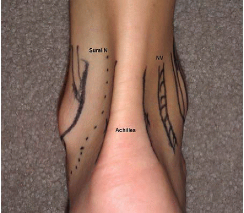 FIGURE 85.4. Posterior aspect of the ankle with location of the posteromedial and posterolateral portals in relation to the nearby at risk structures. NV, neurovascular bundle; N, nerve. |
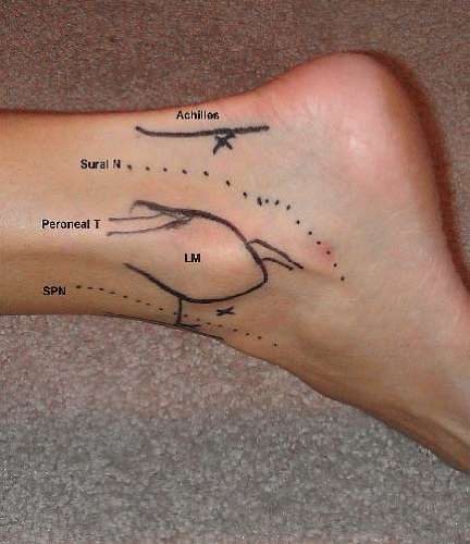 FIGURE 85.5. Lateral aspect of the ankle in the prone position and the setting for hindfoot arthroscopy with location of the posterolateral, accessory lateral, and anterolateral portals. N, nerve; T, tendon; LM, lateral malleolus; SPN, superficial peroneal nerve. |
The technique and instrumentation required for ankle arthroscopy are discussed in Chapter 61.
INTRA-ARTICULAR ANATOMY
Ferkel (4) described a 21-point inspection for the intraarticular anatomy of the ankle. This method represents one of many ways to explore the ankle joint. Regardless of the methodology used by the surgeon, we recommend, as with any joint arthroscopy, a systematic way of examination in order to avoid missing any portions or pathology of the ankle joint. The dome of the talus presents a convexity in the anterior-posterior plane and a concavity in the medial-lateral plane. This particular morphology, as well as the inherent stability of the ankle joint, makes access to it more challenging than for some other joints.
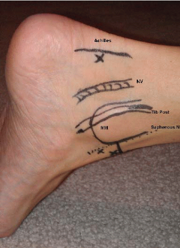 FIGURE 85.6. Medial aspect of the ankle in the prone position and the setting for hindfoot arthroscopy with location of the posteromedial, accessory medial, and anteromedial portals. NV, neurovascular bundle; MM, medial malleolus; N, nerve. |
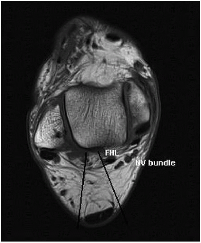 FIGURE 85.7. Axial view of an ankle MRI showing the location and direction of the posterior portals in hindfoot arthroscopy in relation to the Achilles tendon and the neurovascular structures. FHL, flexor hallucis longus; NV, neurovascular. |
The methodology and technique described in this chapter are performed with a 2.7-mm arthroscope and noninvasive ankle distraction (Fig. 85.8). Invasive ankle distraction through the use of calcaneal pin might also be utilized if needed (Figs. 85.9 and 85.10). Once the pathology has been identified and located, a change to the 4.0-mm arthroscope and release of the distraction may take place, particularly to relax the capsule anteriorly. Dowdy and colleagues (12) concluded that noninvasive distraction of 30 lb (13.6 kg) for less than 60 minutes is a safe setup to avoid injury to the nerves crossing the ankle joint.
Related posts:
 Acromioclavicular Separations: Arthroscopic Reconstruction of The Acromioclavicular Joint
Multidirectional and Posterior Shoulder Instability
The Stiff Shoulder: Planning and Treatment Options
Arthroscopic Suprascapular Nerve Release
Arthroscopic Management of Lateral Epicondylitis
Clinical Approach to Articular Cartilage Pathology
Acromioclavicular Separations: Arthroscopic Reconstruction of The Acromioclavicular Joint
Multidirectional and Posterior Shoulder Instability
The Stiff Shoulder: Planning and Treatment Options
Arthroscopic Suprascapular Nerve Release
Arthroscopic Management of Lateral Epicondylitis
Clinical Approach to Articular Cartilage Pathology
Stay updated, free articles. Join our Telegram channel

Full access? Get Clinical Tree


