The Knee
David W. Stoller
Arthur E. Li
Lesley J. Anderson
W. Dilworth Cannon
Magnetic resonance (MR) imaging of the knee has seen significant advances since its initial application, in 1984, for evaluation of the meniscus. MR examination, a noninvasive modality, is now routinely used to assess a wide spectrum of internal knee derangements and articular disorders1,2,3,4 and has virtually replaced conventional arthrography in the evaluation of the menisci and the cruciate ligaments, decreasing both morbidity and costs associated with negative arthroscopic examinations.5,6 In addition to diagnostic benefits, MR imaging has also proved valuable in the selection of surgical candidates and in preoperative planning. Further, improved patient–doctor communication has resulted in more meaningful informed consent, and decreases in the cost of MR knee studies has contributed to their greater acceptance by the orthopaedic community.
Compared with computed tomography (CT) scans, MR imaging provides superior anatomic and pathologic definition of soft tissue, ligaments, fibrocartilage, and articular cartilage. Fast spin-echo (FSE) imaging, used in conjunction with fat-suppression (FS) MR techniques, has extended the sensitivity and specificity of MR in the detection of articular cartilage injuries. Three-dimensional (3D) volume techniques and thin-section two-dimensional (2D) images have demonstrated the versatility of MR imaging in the evaluation of meniscal tears. Additional advantages of MR imaging are multiplanar and thin-section capabilities and the ability to evaluate subchondral bone and marrow. MR imaging, therefore, is recommended instead of CT for the evaluation of bone contusions and occult knee fractures, including tibial plateau fractures. MR has also supplanted nuclear scintigraphy for the characterization of osteonecrosis and can be used to assess the integrity of the overlying articular cartilage surfaces.
The biomechanics of the patellofemoral joint and the normal function of the ligamentous structures of the knee are best assessed with dynamic (rather than kinematic) MR techniques. MR imaging is unique in its ability to evaluate the internal structure as well as the surface of the meniscus.7 With conventional arthrography, intra-articular injection of a contrast
agent permits visualization of surface anatomy but does not allow delineation of fibrocartilage structure or subchondral bone. With MR imaging, intravenous (IV) gadolinium contrast (gadolinium-diethylenetriamine pentaacetic acid [DTPA]) is used to enhance areas of pannus in cases of inflammatory arthritis. Visualization of meniscal repairs and cruciate reconstructions may be improved by either intra-articular (MR arthrography) or IV gadolinium. Joint capsule distention with an MR contrast agent or saline also improves the identification of synovial plicae.
agent permits visualization of surface anatomy but does not allow delineation of fibrocartilage structure or subchondral bone. With MR imaging, intravenous (IV) gadolinium contrast (gadolinium-diethylenetriamine pentaacetic acid [DTPA]) is used to enhance areas of pannus in cases of inflammatory arthritis. Visualization of meniscal repairs and cruciate reconstructions may be improved by either intra-articular (MR arthrography) or IV gadolinium. Joint capsule distention with an MR contrast agent or saline also improves the identification of synovial plicae.
Imaging Protocols for the Knee
Pearls and Pitfalls
Imaging Protocols
FS PD FSE is a fluid-, articular cartilage-, and marrow-sensitive sequence (TR ≥3,000 msec and TE 40–50 msec) that should be performed in the coronal, sagittal, and axial planes.
Sagittal T2* GRE images are helpful for identifying meniscal degeneration, patellar tendinosis, and chondrocalcinosis.
Incorporate a T1-weighted image in at least one imaging plane to obtain an accurate assessment of marrow fat signal intensity changes in sclerosis or edema in cases of trauma, infection, and neoplasia.
Trochlear groove chondral lesions are best evaluated with sagittal images, whereas patellar facet chondromalacia is best assessed on axial images.
MR examinations of the knee are performed in the axial, sagittal, and coronal planes. Although there is no single optimal or correct technique for MR protocols, several general principles assist in the development of sequences for a comprehensive knee examination:
A form of T2 weighting (such as FS proton density [PD] FSE) should be used in each of the three acquisition planes (axial, sagittal, and coronal).
When FSE techniques are used, adding FS improves visualization of articular cartilage, fluid, edema, and contusions.
Articular cartilage is best visualized on PD FSE or FS PD FSE images.
To minimize blurring with FSE and to allow accurate detection of meniscal degenerations and tears, the echo train, which represents the number of echoes per repetition time (TR), must be relatively short (e.g., <6). Thus, meniscal tears may be underdiagnosed if only FSE sequences are used. However, the meniscal fluid interface and meniscal morphology are best seen on FSE (FS PD FSE) images.
A T2* gradient-echo (GRE) sagittal sequence improves the accuracy of detection of meniscal lesions by compensating for the blurring inherent in most FSE acquisitions. (The image blurring seen in FSE MR represents a decrease in spatial resolution along the phase-encoded axis and is more severe with short echo times [TEs].)8
If FS PD FSE images are not acquired, conventional or non-FS FSE T2-weighted images are usually supplemented with a short inversion time (TI) inversion recovery (STIR) sagittal acquisition to improve visualization of osseous contusions and muscle trauma.
Radial imaging, in which multiple planes are rotated from the center of each meniscus or the center of the tibia, can section portions of both the medial and lateral meniscus, in views similar to a conventional arthrogram. Although not routinely used in clinical imaging, radial images display the anatomy of the meniscocapsular junction, including the meniscofemoral and meniscotibial attachments of the deep capsular layer of the knee.
Soft tissue discrimination with MR imaging is excellent, and differentiations can be made among cortex, marrow, ligaments, tendons, muscle, synovium, and vascular and cartilage elements. This differentiation is not possible with conventional radiographic techniques.9,10
Routine Protocols
Pearls and Pitfalls
Routine Protocols
Axial T1 or PD FSE
Subchondral sclerosis in chronic patellofemoral conditions
Axial FS PD FSE
Patellofemoral articular cartilage
Sagittal FS PD FSE (fluid-sensitive sequence)
Chondral lesions, ligament (cruciate) tears, and meniscal morphology (meniscal fluid interface)
Sagittal T2* GRE
Spectrum of meniscal injuries from degeneration to tear
Patellar tendinosis
Chondrocalcinosis
Hemosiderin deposition
Sagittal PD FSE (often used in place of T2* GRE)
Meniscal degeneration or tear. Provides improved intrameniscal signal visualization relative to FS PD FSE but is inferior to T2* GRE or FS PD conventional spin-echo.
Coronal T1 or PD FSE
Sclerosis
Femoral condylar erosions
Subchondral marrow visualization in trauma, infection, or tumor
ACL sprain or scarring
Coronal FS PD FSE
Collateral ligaments
Meniscal root attachments
Confirm continuity of ACL in cases of grade 2 vs. grade 3 ligament injuries
A phased-array extremity coil (available in transmit-receive and in receive-only eight-channel designs) provides a uniform signal-to-noise ratio (SNR) across the knee. Field homogeneity can be improved and image artifacts minimized by the imaging enhancement options selected. For the evaluation of internal knee derangements, routine protocols include T1 or PD-weighted images in the axial, sagittal, and coronal planes. T1-weighted contrast is best for the identification of chronic sclerosis, fracture, microtrabecular injury, and edema. The spectrum of hypointensity changes (intensity, size, and morphology) may not be properly visualized on PD or intermediate-weighted images. T1-weighted contrast visualization of fat signal intensity, whether in marrow or soft tissues, is an important clue to the correct diagnosis. In osteomyelitis, T1-weighted images also provide improved contrast, helping to differentiate between normal and abnormal marrow. Marrow changes in infection may be underestimated or completely overlooked if only PD or FS PD FSE images are acquired. Therefore, T1-weighted sequences are recommended in at least one imaging plane, and may be used in association with PD sequences.
T1 or PD-weighted images cannot be used to replace FS PD FSE contrast imaging. However, FS PD FSE sequences are routinely obtained in the axial, sagittal, and coronal planes. T2*-weighted 2D GRE sagittal images may replace or complement non-FS PD FSE or FS conventional spin-echo PD sagittal images in the evaluation of the meniscus (Fig. 4.1). T2* GRE contrast accurately identifies intrameniscal signal intensity without requiring window level and width modifications to produce increased contrast in meniscal tears. T2* GRE images are also sensitive to patellar tendinosis, chondrocalcinosis, and hemosiderin (as seen in hemorrhage or pigmented villonodular synovitis).
An acquisition matrix (number of phase encodings) of 256 or higher, a field of view of 12 to 14 cm, and 1 to 2 number of excitations (NEX) are routinely used. In children, a field of view of 12 cm or less will increase spatial resolution. The following options are typically used:
GRE images are acquired with an acquisition matrix of 192 or 256.
For FS PD FSE images, TE values of 35 to 45 msec are used to maintain a high SNR. If FS is used in FSE sequences with TE values over 50 msec, SNR is compromised. On FS PD FSE images with TR values of less than 3,000 msec, the articular cartilage–fluid interface is associated with a loss of SNR.
Fast recovery FSE techniques may be used with TR values of less than 3,000 msec without compromising articular cartilage visualization.
Imaging Planes
An axial acquisition through the patellofemoral joint is used as the initial localizer for subsequent sagittal and coronal plane images. Meniscal pathology is evaluated primarily on sagittal plane images. However, the morphology and signal intensity of meniscal fibrocartilage should be assessed secondarily on coronal and axial plane images. The meniscal root attachments are evaluated on posterior coronal images. The cruciate ligaments are best seen on sagittal plane images, with coronal and axial views for secondary visualization and confirmation of pathology. Increased sensitivity for depiction of anterior cruciate ligament (ACL) sprains and scarring is achieved by the complementary use of T1 or PD FSE and FS PD FSE coronal images. The medial and lateral collateral ligaments (MCL and LCL) are displayed on coronal and axial images and can secondarily be visualized on peripheral sagittal images. The articular cartilage surfaces of the medial and lateral compartments are assessed in both coronal and sagittal planes. The patellofemoral joint, including the patellar facets and the trochlear groove chondral surfaces, are assessed on axial and sagittal images. Trochlear groove articular cartilage should be primarily evaluated on sagittal images, avoiding the pitfall of partial volume averaging with the fat pad as seen on FS PD FSE axial images.
Patient Positioning
Although traditionally it was necessary to position the knee in 10° to 15° of external rotation (to align the ACL relatively parallel to the sagittal imaging plane), this external rotation becomes less important when thinner sections (≤3 mm) are used. In addition, the use of sagittal oblique imaging allows the knee to be positioned in a neutral or off-axis orientation. Excessive external rotation of the knee results in elongation of the anterior-to-posterior dimensions of the femoral condyle (especially the lateral femoral condyle) and may decrease accurate visualization of meniscal anatomy and accentuate the normal anatomy of the meniscofemoral ligaments posterior to the posterior horn of the lateral meniscus. Sagittal images are acquired in a plane parallel to the orientation of the intercondylar wall of the lateral femoral condyle, as assessed on an axial localizer, at the location where the medial and lateral femoral condyles fuse.
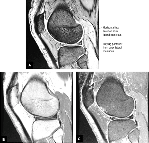 FIGURE 4.1 ● Increased conspicuity of intrameniscal signal intensity tear on T2* GRE (A)compared to PD FSE (B and FSE PD FSE (C sagittal images. |
Slice Thickness
Four-millimeter sections are used for axial and coronal plane images, and 3- to 4-mm-thick sections are used for sagittal images. The maximum slice thickness for evaluation of the meniscus is 4 mm. 3D FT GRE axial images at 0.7 mm thickness provide six to eight sections through the meniscus and display circumferential tear patterns (e.g., longitudinal vs. flap vs. radial tear patterns). At a slice thickness less than 4 mm, routine axial FS PD FSE images demonstrate most circumferential meniscal tear patterns. In the child, 3-mm slices allow optimal medial-to-lateral joint coverage in the sagittal plane and anterior-to-posterior coverage in the coronal plane.
Conventional T2-weighted images are generated with a TR of 2000 msec; a TE of 20 to 80 msec; a 256 × 192 (or 256 × 256) acquisition matrix, and 1 NEX. The use of FSE and STIR (including the FSE version of STIR, or fast inversion recovery) techniques has increased the routine application of long TR protocols while reducing overall imaging time. Effective T2 or T2* contrast can be obtained with refocused 2D FT GRE images, a TR of 400 to 600 msec, a TE of 15 to 25 msec, a flip angle of 20° to 30°, and an acquisition matrix of 256 or 512 × 192. Imaging time can be reduced by using 3D FT GRE volume imaging and a slice thickness of less than 1 mm. The following protocols are typical:
T2 (including FS PD FSE) contrast is helpful in highlighting ligamentous edema and hemorrhage in collateral ligaments in the coronal imaging plane or cruciate ligaments in the sagittal imaging plane.
In patients with degenerative or inflammatory arthritis, sagittal images provide the most information in early synovial reactions (defining the free-edge contour of Hoffa’s fat pad) and cartilage erosions.
Application and Techniques for Routine Protocols
Pearls and Pitfalls
Application and Techniques for Routine Protocols
Echo Time (TE)
Time at which receiver “listens” for signal (sampling)
Dephasing after the RF pulse ends represents T2 effect.
Increased TE = increased dephasing (increased T2 effects)
Increasing the TE decreases SNR. However, resolution increases because the center of k-space is moved to later echoes. Early echoes exhibit dephasing at a faster rate, which results in increased blurring of the image.
Fat saturation decreases the overall SNR of the image by suppressing the signal contribution from fat (FS PD FSE images should not use long TE values [e.g., >. 50 msec]; otherwise the SNR decreases).
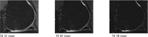
Figure. No caption available.
Fat suppressed PD FSE with TE 31, 47, 78 msec. BW, TR, FOV, Matrix unchanged.
Repetition Time (TR)
TR controls the amount of saturation (T1 effects).
In PD and T2-weighted imaging, the TR must be at least 3 (and preferably 5) times as long as the longest T1 of the tissue being imaged; otherwise T1 contribution will change the overall image contrast.
TR values >,3,000 msec on FS PD FSE images may result in decreased contrast and signal between fluid and articular cartilage.
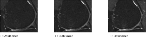
Figure. No caption available.
TR 2500, 3000, 3500 msec respectively. BW, TE, FOV, Matrix unchanged.
Receiver Bandwidth (RBW)
RBW increases SNR since the amplitude of the readout gradient is reduced. However, it can also result in blurring, increased flow pulsation, and decreased number of slices. Date sampling takes longer with lower RBWs.
Blurring in FSE images occurs with lower bandwidth values because of the increase in space between echoes in the echo train length (ETL).
Chemical shift increases with shorter RBWs because of a similar range of frequencies sampled across the field of view.
To minimize image blurring, recommended bandwidths for PD FSE images are 15 to 30 kHz. With bandwidths of 15 to 20 kHz, there is greater SNR.
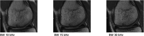
Figure. No caption available.
BW 10, 15, 30 kHz, TR, TE, FOV, and Matrix unchanged.
For identification of trabecular bone contusions and fractures, STIR and FS PD FSE-weighted images are more sensitive than conventional T2- or T2*-weighted protocols. T2* GRE contrast is not helpful in the detection of subchondral bone and marrow pathology. Susceptibility artifacts, secondary to postoperative meniscal or ACL repair, are accentuated on GRE images because of the absence of a 180° refocusing pulse.11,12
Although high-resolution 3D spoiled-grass (SPGR) images display increased anatomic detail at small fields of view (e.g., 4 cm), unless they are obtained in conjunction with FS techniques (fat-suppressed SPGR), they are not as sensitive to subchondral bone and articular cartilage abnormalities as are STIR or FS PD FSE sequences.
FS PD FSE protocols use a TR of 3,000 to 4,000 msec, with a TE of 40 to 50 msec. This PD-weighted TE ensures an adequate SNR when fat suppression is used. FSE protocols require either a prolonged TE (>120 msec) or a PD-like TE (approximately 40 msec) to maintain dynamic contrast between fat and fluid (because of the increased signal intensity from fat compared with that on conventional T2-weighted spin-echo images). With FSE techniques, blurring or decreased resolution is more likely when an echo train length (ETL) greater than 4 and shorter TE sequences are used. For this reason, FSE images alone may not be adequate to identify subtle meniscal degenerations and tears. With TR values less than 2900 msec, fluid–articular cartilage interfaces may become difficult to differentiate, even with FSE and FS.
Magnetization transfer methods can be used in conjunction with 3D grass acquisitions to emphasize articular cartilage-fluid interfaces. With these techniques, tissues with a high macromolecular content or slow macromolecular dynamics, such as cartilage, demonstrate decreased signal intensity in contrast to tissues with a lower macromolecular content, such as blood and synovial fluid.13,14 Overall, FS PD-weighted FSE contrast is the preferred technique for a survey of articular cartilage pathology.
STIR (fast inversion recovery) protocols use a TR of 4000 msec, a TE of 18 msec, a TI of 140 msec, and an ETL of 4. Evaluation of neoplastic lesions, both benign and malignant, requires a combination of T1-, T2- (conventional or FSE), STIR- (FS PD FSE is frequently used in place of STIR because of improved spatial resolution at higher field strengths), or T2*-weighted images in the axial plane to demonstrate compartment and neurovascular anatomy. FS PD FSE or fast inversion-recovery sagittal or coronal images delineate the proximal-to-distal extent of a tumor on one complete image. Although FS eliminates the high signal intensity of fat, it still does not provide the sensitivity of STIR images with T1 and T2 added.15 FS T1-weighted images are acquired when an intra-articular MR contrast agent, such as gadolinium, is used to highlight joint surfaces and distend the capsule. A fluid-sensitive sequence is still required in MR arthrography to evaluate noncommunicating cysts, intrasubstance chondral degeneration, and subchondral edema. FS PD-weighted FSE contrast provides excellent visualization of fluid (which demonstrates high signal intensity) in cases in which intra-articular saline is used instead of a paramagnetic contrast agent for MR arthrography. MR arthrography has limited application and is used primarily to identify retearing of a primary meniscal repair in the postoperative knee.
Artifacts and Photography
Popliteal artery pulsation artifacts can be minimized by exchanging the phase and frequency-encoded directions in the sagittal imaging plane.16
Although high-contrast, narrow–window-width photography is useful for emphasizing or highlighting internal signal intensities within the fibrocartilaginous meniscus, it is not routinely necessary.17 GRE images adequately display the spectrum of meniscal degenerations and tears without contrast adjustment.
Related Muscles
The structure and function of the muscles about the knee joint are described in Figures 4.2, 4.3, 4.4, 4.5, 4.6, 4.7, 4.8, 4.9, 4.10, 4.11, 4.12, 4.13. Muscle origin is indicated in red and insertion in blue. Associated nerves and arteries are yellow and red respectively. The quadriceps group is illustrated in Figures 4.2, 4.3, 4.4, 4.5, the hamstring group in Figures 4.6, 4.7, 4.8, the sartorius in Figure 4.9, the gracilis in Figure 4.10, the popliteus in Figure 4.11, the gastrocnemius in Figure 4.12, and the plantaris in Figure 4.13.
MR Anatomic Atlas of the Knee
Axial Images
In addition to being used as localizers to determine sagittal and coronal coverage, axial plane images have an important role in routine knee evaluation in their own right. Because of their oblique orientation, the medial and lateral patellar facets and the articular cartilage are most accurately demonstrated on axial images through the patellofemoral joint. Patellofemoral disease (i.e., chondromalacia) may be over- or underestimated on sagittal images alone. Axial images are also used to confirm circumferential meniscal tear patterns by directly displaying the entire surface and free edge of the meniscus on one or two axial image locations. Although the axial plane can be used to display meniscal structure, routine axial images at 4 or 5 mm are too thick to be sensitive to meniscal pathology. Sagittal images, which section the meniscus perpendicular to its surface, provide the best demonstration of internal meniscal anatomy and pathology.
Axial joint dissection displays the osseous relations among the patella, femur, and tibia (Fig. 4.14). These anatomic features contribute to the superolateral movement of the patella in full knee extension:
The medial femoral condyle is longer than the lateral condyle and is oriented toward the lateral aspect of the knee as it extends from the posterior to anterior.18
The medial tibial articular facet has a greater anterior-to-posterior dimension than the lateral tibial articular facet, as assessed in the sagittal plane. Both tibial plateau articular facets have a mild concavity in the coronal plane, although the lateral facet displays a convexity in the sagittal plane.
The osseous contribution to the screw-home mechanism causes the tibia to undergo external rotation during the last degrees of full extension as it rolls anteriorly, more on the medial femoral condyle than on the lateral.
The trochlear groove or surface is continuous inferiorly and posteriorly with the intercondylar notch.
The two patellar facets are divided by a median ridge, and the lateral facet is usually larger than the medial facet.
The supratrochlear tubercle represents the nonarticular area of the anterior distal femur, in which the patella rests in full extension.
Outerbridge’s ridge describes the sharp or distinct drop-off between the distal femur articular cartilage and the supratrochlear tubercle.
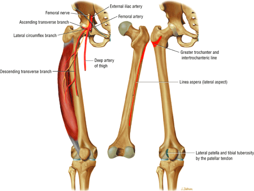 FIGURE 4.2 ● VASTUS LATERALIS The vastus lateralis extends the leg and flexes the thigh (hip) and is one of the quadriceps muscles. (The quadriceps group includes the vastus lateralis, vastus medialis, vastus intermedius, and rectus femoris.) Quadriceps muscle fibers are predominantly type II, adapted for rapid forceful activity. The vastus lateralis obliquus (VLO) fibers of the vastus lateralis muscle interdigitate with the lateral intermuscular septum and insert onto the patella. The VLO may be selectively sectioned in a lateral retinacular release without involving the main vastus lateralis tendon proper. |
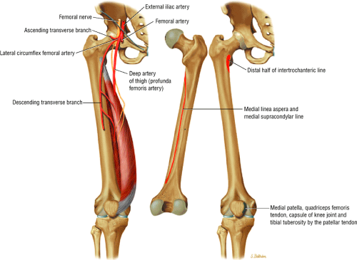 FIGURE 4.3 ● VASTUS MEDIALIS The vastus medialis extends the leg and pulls the patella medially. The quadriceps muscles, which include the vastus lateralis, the vastus medialis, the vastus intermedius, and the rectus femoris, converge distally, forming the quadriceps tendon, which inserts onto the proximal pole of the patella. The vastus medialis assists in preventing patellar dislocation and may be weakened in patellofemoral disorders. Vastus medialis obliquus injuries are associated with transient patellar dislocation. |
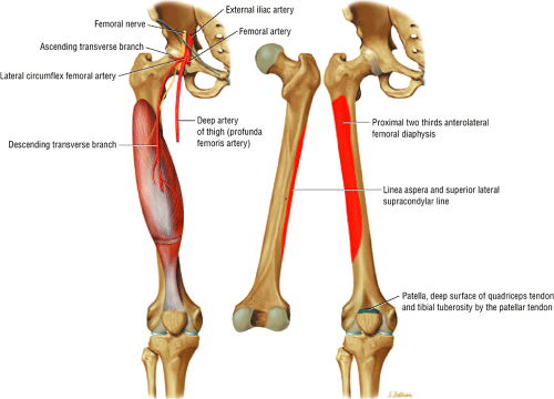 FIGURE 4.4 ● VASTUS INTERMEDIUS The vastus intermedius extends the leg and is occasionally blended with the articularis genu. Quadriceps (vastus lateralis, vastus medialis, vastus intermedius, and rectus femoris) injuries, including strains and tendon ruptures, result from eccentric muscle contractions. The articularis genu muscle is responsible for retracting the knee joint capsule superiorly in extension. |
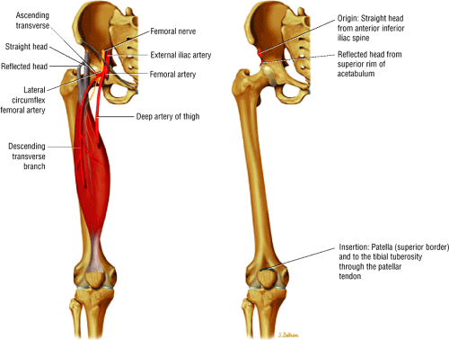 FIGURE 4.5 ● RECTUS FEMORIS The rectus femoris flexes the thigh (hip) and extends the leg (knee). Of the four quadriceps muscles, only the rectus femoris has an origin that crosses the hip joint. Soccer, football, basketball, and track and field athletes are at risk for distal musculotendinous junction injuries and for proximal intrasubstance tears of the musculotendinous junction of the indirect head of the rectus femoris. |
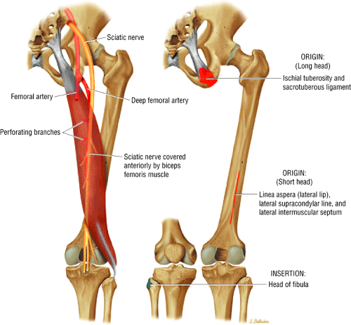 FIGURE 4.6 ● BICEPS FEMORIS The biceps femoris extends the thigh, flexes the leg, and contributes to the lateral stability of the knee as an external rotation of the tibia. The hamstring group (which includes the biceps femoris and the semimembranosus and semitendinosus muscles) all cross the hip and the knee joint, except for the short head of the biceps femoris. Musculotendinous junctions extend the entire length of the muscle and serve as potential sites for strains. The short head of the biceps femoris is innervated by the peroneal branch of the sciatic nerve. The other hamstring muscles are supplied by the tibial branch of the sciatic nerve. |
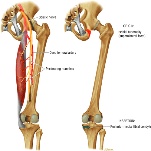 FIGURE 4.7 ● SEMIMEMBRANOSUS The semimembranosus extends the thigh and flexes the leg. As a group, the hamstring muscle group (biceps femoris, semimembranosus, semitendinosus) make up the posterior thigh. Except for the short head of the biceps femoris, the hamstrings arise from the ischial tuberosity and are responsible for ischial avulsion fractures in the young athlete. |
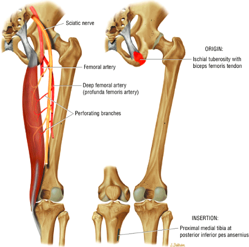 FIGURE 4.8 ● SEMITENDINOSUS The semitendinosus (part of hamstring muscle group) extends the thigh and flexes the leg. The hamstring muscles are important in anterior cruciate ligament reconstructions, in posterolateral knee reconstructions, and in tenodesis for patellar subluxation. The posteromedial tendons are seen on axial knee images at the joint line. Hip hyperflexion with simultaneous knee extension is a mechanism of injury for proximal hamstring injuries in adults and apophyseal avulsions in young skeletally immature athletes. |
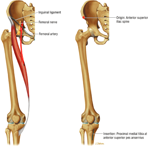 FIGURE 4.9 ● SARTORIUS The sartorius flexes and externally rotates the hip and flexes the leg on the thigh. The anterior superior iliac spine at the origin of the sartorius is a common location for an avulsion fracture. These injuries are seen in sprinters, jumpers, and soccer and football players. |
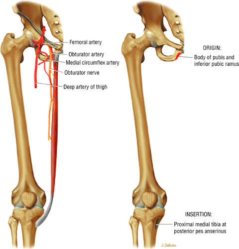 FIGURE 4.10 ● GRACILIS The gracilis adducts the thigh and flexes and internally rotates the leg. It is also used for anterior cruciate ligament reconstructions. The gracilis is the one muscle of the medial aspect adductors of the thigh (the others being the adductor longus, magnus, and brevis and the pectineus) that does not attach to the linear aspect of the femur. |
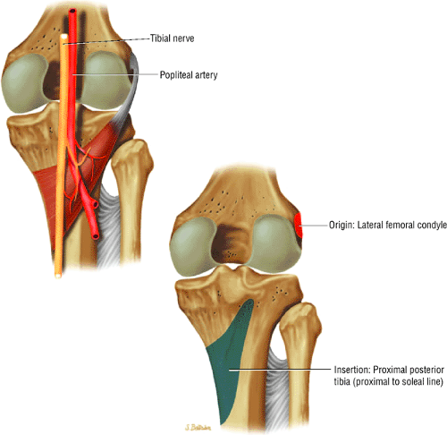 FIGURE 4.11 ● POPLITEUS The popliteus flexes the knee (leg) and internally rotates the tibia at the start of flexion. It is important in injuries to the posterolateral structures. A hiatus in the coronary ligament allows passage of the popliteus tendon to its insertion on the lateral femoral epicondyle. Posterosuperior and posteroinferior popliteomeniscal fascicles attach the popliteus to the lateral meniscus. |
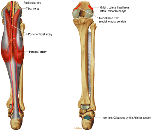 FIGURE 4.12 ● GASTROCNEMIUS The gastrocnemius is responsible for plantar flexion of the foot and also for flexion of the femur on the tibia. Medial head strains are frequently seen in tennis leg. Gastrocnemius fascia is used in augmentation of Achilles tendon repairs. |
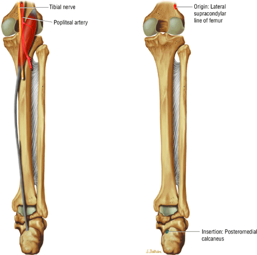 FIGURE 4.13 ● PLANTARIS The plantaris is responsible for plantar flexion of the foot. The short muscle belly is posterolateral at the level of the knee joint and its long tendon courses between the soleus and medial head of the gastrocnemius medially. |
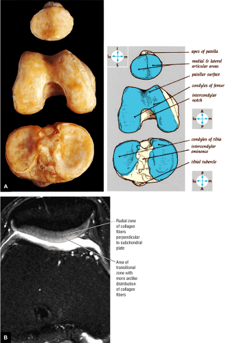 FIGURE 4.14 ● (A) Articular cartilage covers the posterior surface of the patella to the apex. The posterior surface of the patella demonstrates a smaller convex medial facet and larger concave lateral facet. When present, a secondary retropatellar crest subdivides the medial facet into the medial facet proper and an odd facet located between the medial facet proper and the lateral facet. The condylopatellar limiting grooves separate the tibial surfaces of the femoral condyles from the more anterosuperior femoral patellar surface, where the condyles fuse. The medial tibial plateau is concave, whereas the lateral plateau is convex on corresponding sagittal sections. (B) Axial FS PD FSE image showing the laminar display of patellar facet articular cartilage. |
The circumferential surface anatomy of the menisci and attachments of the cruciate and collateral ligaments are shown by disarticulation of the femur from the tibia (Fig. 4.15) and are directly visualized on corresponding axial plane images (Fig. 4.16):
The anterior and posterior horns of the lateral meniscus are attached to the nonarticular area of the tibial plateau, contributing to its relatively circular appearance.18
The anterior and posterior horns of the C-shaped medial meniscus are attached forward on the anterior aspect of the proximal tibia and on the posterior tibia above the posterior cruciate attachment, respectively.
The transverse ligament is a fibrous band that connects the anterior horns of the medial and lateral menisci.
The ligament of Wrisberg and the ligament of Humphrey (the posterior and anterior meniscofemoral ligaments, respectively) are variably present and pass from the posterior horn of the lateral meniscus to the medial aspect of the intercondylar notch. The ligament of Wrisberg passes posterior to the posterior cruciate ligament (PCL), and the ligament of Humphrey passes anterior to it.
The tibial plateau is seen on inferior axial images through the knee joint. The posterior cruciate insertion is displayed on the posterior tibial surface and demonstrates low signal intensity on cross-section.
The popliteus muscle is seen posterior to the tibia at the level of the superior tibiofibular joint.
At the midjoint level, the medial and lateral menisci are seen with uniform low signal intensity. The medial meniscus has an open C-shaped configuration with a narrow anterior horn and wider posterior horn. The lateral meniscus has a more circular shape and consistent width. Sections that are 3 mm or less in thickness display both menisci on axial images.
The transverse ligament of the knee is seen as a band of low signal intensity connecting the anterior horn of the lateral and medial menisci. It can be identified where it transverses Hoffa’s infrapatellar fat pad, which, in contrast to the ligament, demonstrates bright signal intensity.
The semimembranosus and semitendinosus tendons are seen as circular structures of low signal intensity located lateral to the medial head of the gastrocnemius muscle and posterior to the medial tibial plateau. The semimembranosus tendon appears larger than the semitendinosus tendon.
The elliptical sartorius muscle and the circular gracilis tendon are located more medial and posterior than the semimembranosus and semitendinosus tendons and are in line with the MCL, which crosses the peripheral joint line.
Proximal to its insertion on the fibular head, the biceps femoris tendon is positioned anterolateral to the lateral head of the gastrocnemius muscle.
The popliteal artery is found anterior to the popliteal vein, anterior to and between the two heads of the gastrocnemius muscle. Because it is located posterior to the posterior horn of the lateral meniscus, it is potentially at risk for injury during meniscal repair.
In cross-section, the low-signal-intensity LCL, or fibular collateral ligament, may be surrounded by high-signal-intensity fat. The ACL and PCL insertions can be seen within the intercondylar notch. The ACL can be identified superior to the joint line, 15° to 20° off axis, in an anteromedial orientation.19 The PCL is circular in cross-section. The origin of the ACL can be seen on the medial aspect of the lateral femoral condyle, and the PCL can be seen on the lateral aspect of the medial femoral condyle.
Hoffa’s infrapatellar fat pad is bordered by the low-signal-intensity iliotibial band (ITB) laterally, the medial retinaculum medially, and the thick patellar tendon anteriorly.
The common peroneal nerve is located lateral to the plantaris muscle, demonstrates low to intermediate signal intensity, and is encased in fat.
At the level of the femoral condyles, the tibial nerve is located posterior to the popliteal vein and demonstrates intermediate signal intensity.
The larger lateral patellar facet and the oblique medial patellar facet are also seen in the axial plane. The thick articular cartilage surfaces of the patella show intermediate signal intensity on T1- and T2-weighted images. Both the medial and lateral patellar retinacular attachments are seen at the level of the patellofemoral joint and are of low signal intensity. Medial and lateral reflections of the suprapatellar bursa should not be mistaken for retinacular attachments or plicae.
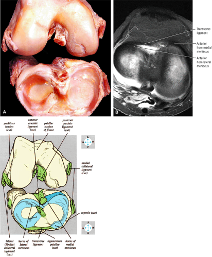 FIGURE 4.15 ● (A) The attachments of the cruciate ligaments and the shape and attachments of the menisci. Sectioning of the cruciate and collateral ligaments allows the femur to be separated from the tibia. (B) Axial FS PD FSE image showing the transverse ligament coursing from the anterior horn of the lateral meniscus to the anterior horn of the medial meniscus. |
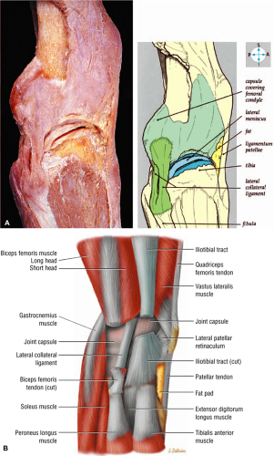 FIGURE 4.16 ● Axial plane images of normal anatomy of the knee. (A T1- or PD-weighted images at this level show tears and strains of muscles about the knee. (B FS PD images show distal quadriceps tendinosis as thickening and increased signal within the quadriceps tendon. (C) T1- or PD-weighted images demonstrate subchondral patellofemoral sclerosis due to overlying chondromalacia. Hypointense trabecular signal or fracture lines in the setting of trauma are associated with bone contusions or fractures. (D) FS PD images are optimal for demonstrating the integrity of the patellofemoral cartilage and presence of medial plica. In addition, sprains and tears of the MCL and fibular collateral ligament, suspected on scans in the coronal plane, can be confirmed in the axial plane. (E) T1 or FS PD FSE images demonstrate fatty muscular atrophy. (F) FS PD images through the intercondylar notch display ACL and PCL tears, sprains, scarring, or degeneration. (G) T1-weighted images are used to display deep venous thrombosis as edema throughout the posterior calf muscles. A blooming artifact from clot distention of the popliteal vein can be seen on GRE images. (H) FS PD images through the menisci are used to triangulate on and further characterize meniscal tears seen on images in other planes. The appearances of radial tears, longitudinal tears, and flap tears are characteristic on axial images. (I) T1-weighted images through the lateral and medial tibial plateau show well-characterized tibial plateau fractures. (J) FS PD images show the tibial nerve and common peroneal nerve as common locations for schwannomas. The course of both of these nerves is displayed on axial images. (K) T1-weighted images show attenuated tendons. Harvesting of the sartorius, gracilis, or semitendinosus tendons for an ACL graft can be inferred when these tendons are attenuated after ACL grafting. (L) FS PD images display edema and fragmentation of the tibial tubercle as well as inflammation of the distal patellar tendon. |
Sagittal Images
Sagittal plane dissection displays the components of the medial (Fig. 4.17) and lateral (Fig. 4.18) collateral ligaments and the adjacent capsule:
The patellofemoral compartment, quadriceps, and patellar tendon are demonstrated on midsagittal dissections (Fig. 4.19). The suprapatellar bursa (pouch) extends 5 to 7 cm proximal to the superior pole of the patella.18 Superficial medial dissection displays the conjoined pes anserinus tendons (semitendinosus, gracilis, and sartorius) as they course along the posteromedial aspect of the knee. The pes anserinus runs superficial to the distal MCL and inserts into the anteromedial tibial crest distal to the joint line. On the lateral aspect of the knee, the LCL and the more posteriorly located fabellofibular ligament (structures of the posterolateral corner of the knee) can be seen. The fabellofibular and arcuate ligaments have insertions on the posterior aspect of the fibular styloid, posterior and deep to the LCL. These ligaments course superficially and posteriorly, blending with the origin of the lateral head of the gastrocnemius and the oblique popliteal ligament. The arcuate ligament extends toward the popliteus capsular hiatus.
The ACL and PCL are best displayed on sagittal images (Fig. 4.20). The LCL, or fibular collateral ligament, and the biceps femoris tendon also may be seen on peripheral sagittal sections. Images in the sagittal plane are key in evaluating meniscal anatomy for both degenerations and tears. The MCL is usually partially defined in the sagittal plane on peripheral medial sagittal images. Complex meniscal and bucket-handle tears may require coronal images to identify displaced meniscal tissue or fragments.
On medial sagittal images, the low-signal-intensity semimembranosus tendon and intermediate-signal-intensity muscle are seen posteriorly. The vastus medialis muscle makes up the bulk of the musculature anterior to the medial femoral condyle. On T1-weighted images,
fatty (i.e., yellow) marrow demonstrates bright signal intensity, whereas adjacent cortical bone demonstrates uniform low signal intensity. Femoral and tibial hyaline articular cartilage demonstrates intermediate signal intensity on T1- and conventional T2-weighted images, bright signal intensity on T2*-weighted images, and low to intermediate signal intensity on FS PD FSE images. The anterolateral femoral articular cartilage, which is particularly thick, is frequently the site of early erosions or attenuation in osteoarthritis (trochlear groove chondromalacia). The tibial cortex appears thicker than the femoral cortical bone because of a chemical-shift artifact.
The medial meniscus, which is composed of fibrocartilage, demonstrates uniform low signal intensity. The body of the medial meniscus has a continuous bowtie shape on at least one or two consecutive sagittal images taken in 4- to 5-mm sections. In medial compartment images approaching the intercondylar notch, the separate anterior and posterior horns of the medial meniscus can be seen. The meniscal horns appear as opposing triangles on a minimum of two or three consecutive sagittal images. The posterior horn root attachment of both menisci should always be identified adjacent to the intercondylar notch. The posterior horn of the medial meniscus is larger than the opposing anterior horn. The medial head of the gastrocnemius muscle sweeps posteriorly from its origin along the distal femur. A small band of high-signal-intensity fat, representing the bursa, is seen between the posterior horn of the medial meniscus and the low-signal-intensity posterior capsule.
When sagittal images are viewed in the medial to lateral direction, the PCL is seen before the ACL comes into view. The thick, uniform, low-signal-intensity PCL arcs from its anterolateral origin on the medial femoral condyle to its insertion on the posterior inferior tibial surface. With partial knee flexion, the convex curve of the PCL becomes taut as the anterolateral band or bundle of the PCL is lax in extension. The anterior and posterior meniscofemoral ligaments (the ligaments of Humphrey and Wrisberg, respectively) are seen individually or together on either side of the PCL.
In the lateral portion of the intercondylar notch, the ACL extends obliquely from its semicircular origin on the posteromedial aspect of the lateral femoral condyle to its insertion, which starts 15 mm from the anterior border of the tibial articular surface (between the tibial
spines). On average, it is 30 mm in length through the anterior intercondylar area.20,21
Although the ACL is composed of two functional bands of fibers (the anteromedial and posterolateral bands [AMB and PLB]), these bands cannot be differentiated on sagittal images. ACL fibers may display minimally higher signal intensity than those of the PCL, and this difference is seen independent of a partial-volume effect with the lateral femoral condyle. Normally, the ACL is seen on at least one sagittal image when the knee is properly positioned or when proper sagittal oblique images are prescribed. Fiber-bundle striations of the ACL are prominent at femoral and tibial attachments, especially when oblique sagittal images are performed to display attachment sites.
Portions of both cruciate ligaments may be observed on the same sagittal section. Excessive external rotation of the knee causes elongation of the anterior-to-posterior dimensions of the femoral condyles. Excessive internal rotation also prevents adequate visualization of the ACL unless sagittal oblique images are used to compensate for redirecting the ACL away from the orthogonal sagittal plane.
On midsagittal sections, the quadriceps and patellar tendons, which demonstrate low signal intensity, are seen at their anterior attachments to the superior and inferior patellar poles, respectively. Hoffa’s infrapatellar fat pad is directly posterior to the patellar tendon and demonstrates bright signal intensity. The posterior patellar articular cartilage displays a smooth or a convex arc on sections through the medial and lateral patellar facets. In the absence of joint fluid, the collapsed patellar bursa is not seen proximal to the superior pole of the patella.
On intercondylar sagittal images, the popliteal vessels are seen in long axis, with the artery in an anterior and the vein in a posterior position.
On extreme sagittal sections, the conjoined insertion of the LCL and the biceps femoris tendon on the fibular head can be identified. The lateral head of the gastrocnemius muscle is seen posterior to the fibula and follows an inferior course from the distal lateral femoral
condyle behind the popliteus muscle. The low-signal-intensity popliteus tendon and its intermediate-signal-intensity sheath are seen in their expected anatomic location, between the capsule and the periphery of the lateral meniscus. Separate synovium-lined fascicles, or struts, of the menisci allow intra-articular passage of the popliteus tendon. In its middle third (i.e., body), the C-shaped lateral meniscus also demonstrates a bowtie shape. On more medial sections through the lateral compartment, the separate triangular shapes of the anterior and posterior horn, which are oriented toward each other and are nearly symmetric in size and shape, can be distinguished.
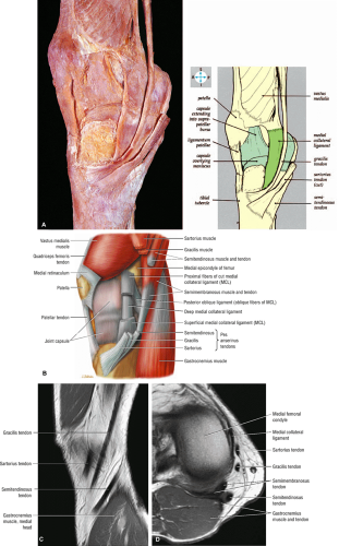 FIGURE 4.17 ● (A) Pes anserinus tendons seen with superficial dissection from the medial aspect of the knee. (B) Exposure of layer 3 or deep MCL on the medial aspect of the knee. Pes tendons are sectioned and shown on sagittal (C) and axial (D) PD FSE images. |
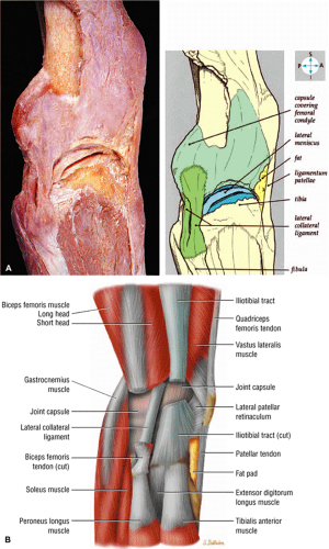 FIGURE 4.18 ● (A) Dissection from the lateral aspect shows the LCL and the meniscus, which are revealed by removing part of the capsule. (B) Lateral retinaculum and related structures and attachment of the iliotibial band, also referred to as the iliotibial tract, to Gerdy’s tubercle. The thickened fascia lata forms a longitudinal fiber band referred to as the iliotibial tract. The iliotibial tract and tensor fasciae latae originate from the anterior superior iliac spine. The distal iliotibial tract divides into anterior intermediate and posterior fibers. Strong “Kaplan fibers” bind the iliotibial tract to the femoral diaphysis. |
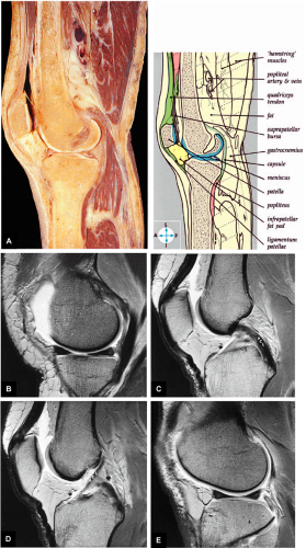 FIGURE 4.19 ● (A) A sagittal section through the knee joint shows the articular surfaces and suprapatellar pouch. Representative sagittal MR arthrographic images through the medial compartment (B), PCL (C), ACL (D), and lateral compartment (E). |
Coronal Images
Posterior-to-anterior coronal anatomic dissection (Fig. 4.21) demonstrates the posterior capsule, the popliteus tendon, the cruciate ligaments and menisci (Fig. 4.22), the collateral ligaments (Figs. 4.23 and 4.24), and the extensor mechanism (see Fig. 4.24). Coronal plane images (Fig. 4.25) are most frequently used to identify collateral ligament anatomy. Images in this plane also display the posterior femoral condyles, which are common sites of articular erosions. The cruciate ligaments, although displayed to best advantage in the sagittal plane, can also be identified on coronal and axial images. The oblique popliteal ligament and arcuate popliteal ligament define the posterior capsule. The low-signal-intensity popliteal vessels are also identified on posterior coronal images:
The LCL (fibular collateral ligament) is seen as a low-signal-intensity cord stretching from its insertion on the fibular head to the lateral epicondyle of the femur. It is separated from the lateral meniscus by the thickness of the popliteus tendon.
At the level of the femoral condyles, the meniscofemoral ligaments (the ligaments of Wrisberg and Humphrey) may be observed as thin, low-signal-intensity bands extending from the posterior horn of the lateral meniscus to the lateral surface of the medial femoral condyle. The ligament of Humphrey is variable in size. Although one or the other of the branches of the meniscofemoral ligament may be identified on one third of knee studies, the coexistence of the two is seen in only 3% of examinations.22
The functional location of the AMB and PLB of the ACL may be discerned on anterior and posterior coronal images, respectively.
The PCL is circular and of uniform low signal intensity on anterior and mid-coronal sections. On posterior coronal images, the triangular attachment of the PCL can be differentiated as it fans out from the lateral aspect of the medial femoral condyle.
The MCL, or tibial collateral ligament, is identified on mid-coronal sections, anterior to sections in which the femoral condyles appear to fuse together with the distal metaphysis. The MCL is seen as a band of low signal intensity extending from its femoral epicondylar attachment to the medial tibial condyle. It consists of superficial and deep layers attached to the periphery of the medial meniscus. The femoral and tibial attachments of the uninjured or intact MCL are uniformly dark (low signal intensity) and are indistinguishable from underlying cortical bone. From the plane of the posterior femoral condyle, the MCL can be seen on at least two or three coronal images if they are acquired with 5-mm sections and no interslice gap. A line of intermediate signal intensity separating the medial meniscus from the deep layer of the MCL represents a small bursa.
The body and the anterior and posterior horns of the medial and lateral menisci are seen as distinct segments and not as opposing triangles as on sagittal images. On posterior coronal images, the plane of section is parallel with the posterior curve of the C-shaped menisci, and the posterior horn may be seen as a continuous band of low signal intensity. The root attachments of both meniscal fibrocartilages are visualized in the same posterior coronal plane image as the PCL in its distal tibial insertion.
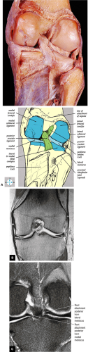 FIGURE 4.22 ● (A) The posterior part of the capsule has been removed to reveal the ACL, PCL, and menisci.(B) A coronal image obtained more anteriorly in the plane of the MCL (M) and iliotibial tract (it). P, PCL; A, ACL; mm, medial meniscus; lm, lateral meniscus. (C) Root attachment of the posterior horn of the medial and lateral meniscus. |
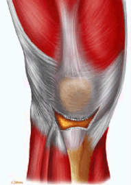
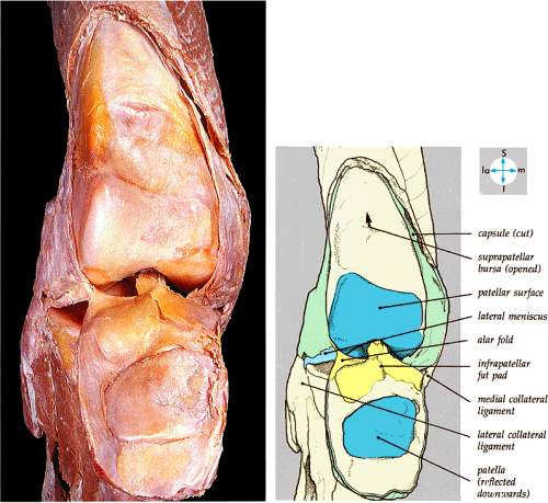 FIGURE 4.23 ● The interior of the joint and the suprapatellar pouch are exposed by opening the capsule anteriorly and reflecting the patella downward. |
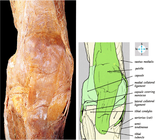 FIGURE 4.24 ● Superficial dissection from the anterior aspect shows the ligamentum patellae, capsule, and MCL and LCL. |
Mid-coronal sections display the anterior tibial spine, whereas anterior images are marked by the high signal intensity of Hoffa’s infrapatellar fat pad anterior to the lateral knee compartment. Anteriorly, the ITB blends with the lateral patellar retinaculum, and the vastus medialis is in continuity with its medial retinacular patellar attachment. The low-signal-intensity fibers of the quadriceps and patellar tendons can be identified on most anterior sections in the same plane as the patella.
Imaging Checklist for the Knee
MR examination of the knee of includes evaluation of the major structures—the medial and lateral collateral ligaments, theseparated from the lateral meniscus by the thickness of the posteromedial and posterolateral corners, the ITB, the medial and lateral compartment cartilage, the patellofemoral cartilage, plicae, quadriceps and patellar tendons, and the osseous structures23—as well as identification of pathologic findings such as popliteal cysts, effusions, loose bodies, and synovitis. The checklist approach is optimal when viewing images on a workstation with the ability to view multiple planes and sequences at the same time.
Coronal Plane Checklist
In the coronal plane, the primary checklist structures are (1) the collateral ligaments. Additional structures to be examined include (2) the cruciate ligaments, (3) the menisci, (4) articular cartilage, (5) osseous structures, and (6) the iliotibial tract.
(1) Collateral Ligaments
Medial Collateral Ligament (Fig. 4.26)
The MCL is initially located on the image that demonstrates fusion of the medial and lateral femoral condyles. On this image, the posterior aspect of the MCL is seen as a hypointense band of fibers extending along the peripheral aspect of the medial femoral condyle and medial tibial plateau. Proceeding in an anterior direction, the entire posterior-to-anterior extent of the MCL is demonstrated over the next one or two images. A coronal image through the intact posterior fibers of the MCL may not demonstrate a partial-thickness tear, since these injuries preferentially involve the anterior fibers. It is important to examine the entire course of the MCL from its origin on the medial femoral condyle to its distal insertion on the proximal tibial metaphysis, as tears can occur anywhere along this course.
Lateral Collateral Ligament (Fig. 4.27)
Identification of the LCL also starts with the image on which the femoral condyles fuse. The origin of the LCL from the lateral femoral condyle is visualized on either this image or one image posterior to it. Unlike the MCL, which has a nearly straight vertical course, the LCL runs posteriorly in an oblique inferior direction. Proceeding in a posterior direction, it is demonstrated in its entire course, to the attachment of the LCL at the tip of the fibular head, over two images.
(2) Cruciate Ligaments
Anterior Cruciate Ligament (Fig. 4.28)
Identification of the ACL again starts with the image that demonstrates the femoral condyles fusing. Proceeding for two or three images in a posterior direction, the origin of the ACL is identified along the medial margin of the lateral femoral condyle. From this image location, proceeding in an anterior direction, the entire posterior-to-anterior course of the ACL is demonstrated over the next five or six images. The ACL follows an inferior oblique course to its insertion on the anterior tibia. Individual fibers of the normal ACL can be distinguished (taut and dark), separated by bands of intermediate- to high-signal-intensity normal synovium. Scarred, degenerated, or sprained ACL fibers are indistinct, thickened, or increased in signal intensity. At the site of an acute tear, the fibers are replaced by edema, hemorrhage, or synovitis. Fibers proximal and distal to the tear appear wavy, lax, and edematous.
Posterior Cruciate Ligament (Fig. 4.29)
The origin of the PCL, at the anterior lateral aspect of the medial femoral condyle, can be identified on or near the same image as the distal insertion of the ACL. On coronal images, proximal PCL fibers are seen in cross-section. Progressing in a posterior direction for four or five images, the PCL fibers can be seen to gradually turn 90° and course vertically downward to their insertion on the posterior tibia.
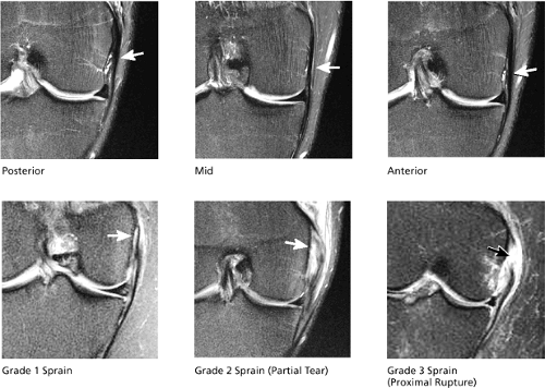 FIGURE 4.26 / MEDIAL COLLATERAL LIGAMENT. |
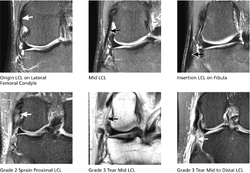 FIGURE 4.27 / LATERAL (FIBULAR) COLLATERAL LIGAMENT. |
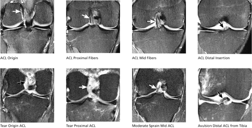 FIGURE 4.28 / ANTERIOR CRUCIATE LIGAMENT. |
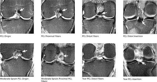 FIGURE 4.29 / POSTERIOR CRUCIATE LIGAMENT. |
(3) Menisci (Fig. 4.30)
The posterior horns of the menisci are first identified on the coronal image on which the fibula first comes into view. The meniscal root ligaments are seen as thin, short, hypointense fibrous bands that extend from the inner margins of the posterior horns to where they attach centrally near the tibial spines. The root is a frequent location for radial tears that disrupt the root attachment and undermine the meniscal hoop containment fibers, which keep the meniscus from extruding peripherally with joint loading.
The body segments of the menisci are demonstrated on coronal images anterior to the level of the fibula. Continuing in an anterior direction, the anterior horns can be seen at the margins of the anterior edge of the tibia. Normal anterior horn and body segments appear on coronal images as black triangles with sharp tips, which represent the inner free edge. There is no increased signal interrupting either the superior or inferior articular surface of the meniscus.
On coronal images, displaced flaps of meniscal tissue are seen as meniscal tissue protruding either from the body segment into the coronary or meniscofemoral recesses or from the posterior horn toward the tibial spines. A triangle of missing tissue near the free edge on the undersurface or inferior leaflet of the meniscus is characteristic of a flap tear. If seen, the coronary recess, meniscofemoral recess, and intercondylar notch should be carefully examined to identify a displaced flap of meniscal tissue corresponding to the area of deficient meniscal fibrocartilage.
(4) Articular Cartilage (Figs. 4.31 and 4.32)
Cartilage can be seen covering the medial and lateral tibial plateau and distal femur. On coronal images, the anterior horns of the menisci are the landmarks for demarcating cartilage compartments. At and posterior to the anterior horns, cartilage covers the femoral condyle and tibial plateau, and is classified as medial or lateral compartment cartilage. On images anterior to the anterior horns, cartilage that covers the distal anterior femur (i.e., the trochlear groove) is referred to as “trochlear groove” cartilage and is part of the patellofemoral compartment. In the medial and lateral compartments, cartilage covers the mid-weight-bearing surfaces of both the tibial plateau and femoral condyle, which contact each other in extension.
The cartilage surface continues posteriorly along the posterior surface of the femoral condyle, which touches the tibia in flexion. It is necessary to examine the entire cartilage surface from anterior to posterior. Chondral abnormalities of the posterior femoral condyle are easily overlooked if the posterior cartilage surfaces are not carefully evaluated. Cartilage is inspected for chondral fissures, erosions, fibrillation, thinning, defects, and flap formation. The underlying subchondral bone is also examined to identify reactive bone marrow edema or cystic change subjacent to areas of chondral erosion.
Evaluation of the articular cartilage surfaces includes examination of the joint spaces for loose bodies originating from sites of chondral defects or erosions. Loose bodies vary in appearance and can manifest as tiny spots of debris; free-floating thin, elongated, intermediate intensity cartilage fragments; cartilage
bodies with varying amounts of subchondral bone attached; or predominantly osseous fragments of varying sizes and shapes. On coronal images, loose bodies are often identified along the posterior joint line posterior to the PCL and menisci, along the anterior joint line anterior to the ACL, and within the patellofemoral recesses between the patella and distal femur.
bodies with varying amounts of subchondral bone attached; or predominantly osseous fragments of varying sizes and shapes. On coronal images, loose bodies are often identified along the posterior joint line posterior to the PCL and menisci, along the anterior joint line anterior to the ACL, and within the patellofemoral recesses between the patella and distal femur.
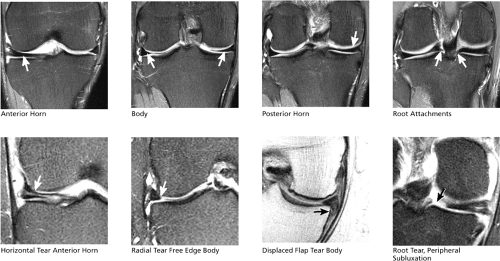 FIGURE 4.30 / MENISCI. |
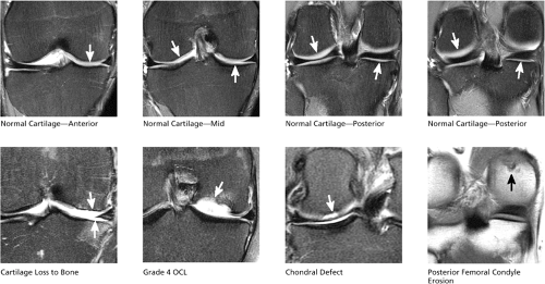 FIGURE 4.31 / MEDIAL AND LATERAL COMPARTMENT CARTILAGE. |
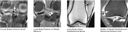 FIGURE 4.32 / LOOSE BODIES. |
(5) Osseous Structures (Fig. 4.33)
The cortical, subchondral, and trabecular bone are examined for the presence of fractures, contusions, stress-related edema, infection, osteonecrosis, or neoplasms.
(6) Iliotibial Tract (Fig. 4.34)
The distal attachment of the iliotibial tract is visualized at the anterolateral margin of the tibial plateau (called Gerdy’s tubercle), and the tendon is identified on at least four or five consecutive coronal images. The normal iliotibial tract should appear taut and thin. Focal thickening suggests scarring, and in the proper clinical setting, high-signal-intensity edema and synovitis deep to the tendon suggest ITB friction syndrome.
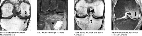 FIGURE 4.33 / OSSEOUS STRUCTURES. |
Sagittal Plane Checklist
In the sagittal plane, the primary checklist structures are (1) the medial and lateral menisci, (2) the chondral surfaces of the medial and lateral compartment, (3) the trochlear groove cartilage, and (4) the anterior and posterior cruciate ligaments. Other structures observed in the sagittal plane include (5) the posteromedial and posterolateral corners, (6) the patellar and quadriceps tendons, (7) subchondral bone and marrow, (8) joint fluid/effusion, (9) Hoffa’s fat pad, and (10) plicae. The tibiofibular joint, collateral ligaments, lateral tendons, and patellar facet articular cartilage may also be evaluated.
(1) Medial and Lateral Menisci (Fig. 4.35)
The body of the meniscus is identified between the femoral condyle and tibial plateau on peripheral images through the medial or lateral compartment. The body segment is bowtie-shaped. A small gap in the middle portion of the bowtie indicates a free edge radial tear of the body segment. An eccentric gap, off to one side of the bowtie, indicates a free edge radial tear involving the junction of the body with the anterior or posterior horn. In meniscal flap tears, the first sagittal image on
which the peripheral aspect of the body segment is seen is useful for visualizing flaps of meniscal tissue displaced into the coronary or meniscofemoral recess. The anterior and posterior horns of the meniscus appear as black triangles with a sharp inner free edge. The root of the posterior horn can be identified in the peripheral aspect of the medial or lateral compartment, approaching the intercondylar notch. A radial tear through the root of the posterior horn appears as a “ghost meniscus,” with absence of meniscal signal in the expected location of the posterior horn root. The “ghost meniscus” appearance is due to localization of the sagittal image in a plane directly through the gap in the posterior horn meniscal tissue caused by the radial tear.
which the peripheral aspect of the body segment is seen is useful for visualizing flaps of meniscal tissue displaced into the coronary or meniscofemoral recess. The anterior and posterior horns of the meniscus appear as black triangles with a sharp inner free edge. The root of the posterior horn can be identified in the peripheral aspect of the medial or lateral compartment, approaching the intercondylar notch. A radial tear through the root of the posterior horn appears as a “ghost meniscus,” with absence of meniscal signal in the expected location of the posterior horn root. The “ghost meniscus” appearance is due to localization of the sagittal image in a plane directly through the gap in the posterior horn meniscal tissue caused by the radial tear.
 FIGURE 4.34 / ILIOTIBIAL TRACT. |
(2) Medial and Lateral Compartment Articular Cartilage (Fig. 4.36)
Cartilage covers the medial and lateral femoral condyles from anterior to posterior. The anterior meniscal horn demarcates the division between the trochlear groove cartilage (located anterior to the anterior horn), and the femoral condyle cartilage (located at and posterior to the anterior horn). Covering the mid-weight-bearing surfaces of the femoral condyles, the cartilage extends posteriorly past the level of the posterior horn of the meniscus and posterosuperiorly to cover the extreme posterior aspect of the femoral condyle subjacent to the gastrocnemius tendon origins. The extreme posterior part of the femoral
condyle becomes the weight-bearing surface when the knee is in flexion. Chondral abnormalities may be seen anywhere along the articular surface. Cartilage also covers the articular surfaces of the medial and lateral tibial plateau.
condyle becomes the weight-bearing surface when the knee is in flexion. Chondral abnormalities may be seen anywhere along the articular surface. Cartilage also covers the articular surfaces of the medial and lateral tibial plateau.
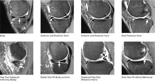 FIGURE 4.35 / MEDIAL MENISCUS. |
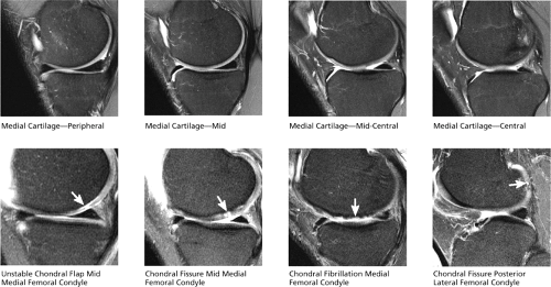 FIGURE 4.36 / MEDIAL COMPARTMENT CARTILAGE. |
After examination of the cartilage for chondral abnormalities, the underlying subchondral bone is inspected for reactive bone marrow edema and cystic change, and the joint recesses are evaluated for the presence of loose bodies.
(3) Trochlear Groove Cartilage (Fig. 4.37)
The trochlear groove is a V-shaped concave notch formed by the inward sloping contour of the anterior-inferior medial and lateral femoral condyles. The concave surfaces of the trochlear groove surfaces articulate with the convex surfaces of the patella. On sagittal images, any cartilage covering the femoral condyles anterior to the anterior horns of the menisci is considered trochlear groove cartilage. Anatomically, the trochlear groove comprises medial, mid, and lateral articular surfaces. The entire extent of the trochlear groove chondral surface from medial to lateral can be examined on sagittal images.
Cartilage covers three anatomic regions of the patella. The lateral articular surface of the patella is called the lateral patellar facet, the central portion is called the median ridge, and the medial articular surface is referred to as the medial facet. As a rule, the median ridge cartilage is identified on midline sagittal images, the medial facet cartilage is visualized medial to the midline, and the lateral facet cartilage is seen lateral to the midline. This rule does not apply in cases of patellar subluxation. The median ridge cartilage can also be identified by finding the sagittal image through the thickest portion of the patella in the anteroposterior dimension.
(4) Anterior and Posterior Cruciate Ligaments (Fig. 4.38)
The entire course of the ACL and PCL can be seen on two or three midline sagittal images. Complete acute tears are characterized with respect to involvement of the origin, proximal third, middle third, or distal attachment. Full-thickness tears present as complete discontinuity of ACL or PCL fibers, whereas sprains are characterized by continuous fibers traversing the entire length of the notch, although individual fibers display laxity, increased signal intensity, or loss of definition. In the case of ACL scarring, fibers also appear lax or indistinct.
Sagittal images should also be examined for anterior translation of the tibia beneath the femur, since this presentation indicates ACL insufficiency from previous injury or scarring. ACL insufficiency can exist even though the ACL appears continuous on MR images, due to laxity of scarred fibers, scarring of a previously torn ACL, or the PCL mimicking an intact ACL appearance.
(5) Posteromedial and Posterolateral Corners (Figs. 4.39 and 4.40)
A secondary role for sagittal imaging is to assess the structures of the posteromedial corner, including all tendons, ligaments, and capsular structures that traverse the posterior medial quadrant
of the knee. Individual tendons are not always depicted on each MR image. The MCL is seen on the most peripheral sagittal image. Subsequent images depict the distal sartorius, gracilis, and semitendinosus tendons coursing obliquely posteromedial to the tibia. The origin of the semimembranosus can be seen at the posteromedial margin of the medial tibial plateau. The origin of the medial head of the gastrocnemius is seen at the posteromedial margin of the medial femoral condyle metaphysis. The meniscotibial and meniscofemoral ligaments (also known as the meniscocapsular ligaments) are seen along the entire course of the posteromedial corner, fanning out and away from the posterior edge of the posterior horn of the medial meniscus. The meniscocapsular ligaments also can be seen extending along the anteromedial quadrant to form a full arc around the entire course of the meniscus. Meniscocapsular separation and tears are characterized by fluid signal interrupting the normally dark to intermediate strands of meniscocapsular ligament, and can occur at any point along the course of the ligaments.
of the knee. Individual tendons are not always depicted on each MR image. The MCL is seen on the most peripheral sagittal image. Subsequent images depict the distal sartorius, gracilis, and semitendinosus tendons coursing obliquely posteromedial to the tibia. The origin of the semimembranosus can be seen at the posteromedial margin of the medial tibial plateau. The origin of the medial head of the gastrocnemius is seen at the posteromedial margin of the medial femoral condyle metaphysis. The meniscotibial and meniscofemoral ligaments (also known as the meniscocapsular ligaments) are seen along the entire course of the posteromedial corner, fanning out and away from the posterior edge of the posterior horn of the medial meniscus. The meniscocapsular ligaments also can be seen extending along the anteromedial quadrant to form a full arc around the entire course of the meniscus. Meniscocapsular separation and tears are characterized by fluid signal interrupting the normally dark to intermediate strands of meniscocapsular ligament, and can occur at any point along the course of the ligaments.
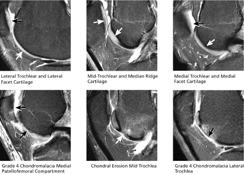 FIGURE 4.37 / PATELLAR AND TROCHLEAR GROOVE CARTILAGE. |
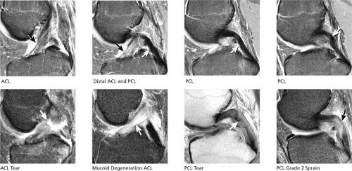 FIGURE 4.38 / ANTERIOR AND POSTERIOR CRUCIATE LIGAMENTS. |
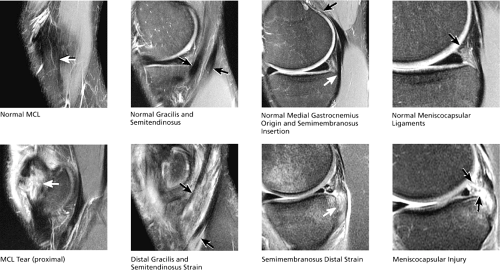 FIGURE 4.39 / POSTEROMEDIAL CORNER. |
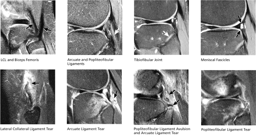 FIGURE 4.40 / POSTEROLATERAL CORNER. |
The most peripheral image through the posterolateral corner demonstrates the V-shaped convergence of the fibular collateral ligament (anterior limb of the “V”) and the distal biceps femoris tendon (posterior limb of the “V”) inserting on the proximal fibula. On the next, deeper, image the origin of the popliteus tendon along the posterolateral aspect of the lateral femoral condyle is displayed. Occasionally, the popliteofibular ligament is also displayed on this same image and is seen as a dark band of fibers extending from the origin of the popliteus tendon to the superior tip of the fibula. The course of the popliteus tendon, as it sweeps posterolateral to the posterior horn of the lateral meniscus, can be followed over the next four or five images.
The arcuate ligament is a thin dark band occasionally visualized posterior to the popliteus tendon on sagittal images. Severe edema posterior to the popliteus tendon, with joint fluid in the space beyond the normal posteromedial capsular structures, is a clue to the presence of an arcuate ligament tear.
Similar to the medial meniscocapsular ligaments, the lateral meniscocapsular ligaments extend from the peripheral edge of the lateral meniscus along the entire outer circumference of the meniscus.
The tibiofibular joint is also examined for fibular fractures, joint arthrosis, and synovial cysts. Cysts that abut or displace the peroneal nerve may cause peroneal neuritis.
(6) Patellar and Quadriceps Tendons (Fig. 4.41)
The distal quadriceps tendon and the entire course of the patellar tendon can be seen on five or six consecutive sagittal images through the patella. All sagittal images displaying tendon tissue should be examined carefully, since partial tears and tendinosis occasionally involve only the peripheral margin of the tendons. Distal quadriceps tendinosis is characterized by thickening and increased signal intensity at the distal quadriceps insertion on the superior pole of the patella. Patellar tendinosis commonly occurs at the proximal origin of the patellar tendon on the inferior pole of the patella. Patellar tendon inflammation
associated with Osgood-Schlatter disease is displayed on sagittal images at the distal insertion of the patellar tendon on the tibial tubercle. Patella baja and patella alta are also diagnosed on sagittal images based on the relative position of the patella (and length of the patellar tendon) with respect to the femur.
associated with Osgood-Schlatter disease is displayed on sagittal images at the distal insertion of the patellar tendon on the tibial tubercle. Patella baja and patella alta are also diagnosed on sagittal images based on the relative position of the patella (and length of the patellar tendon) with respect to the femur.
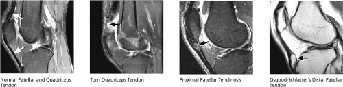 FIGURE 4.41 / PATELLAR AND QUADRICEPS TENDON. |
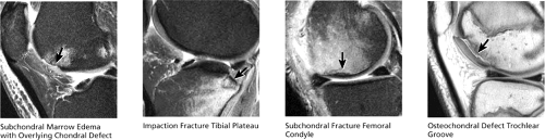 FIGURE 4.42 / SUBCHONDRAL BONE AND MARROW. |
(7) Subchondral Bone and Marrow (Fig. 4.42)
The subchondral bone surfaces and marrow of the femoral condyles, tibial plateau, and patella are examined for the presence of edema, fractures, or masses. In chondromalacia, reactive bone marrow edema can be seen in the subchondral bone directly underlying the areas of significant chondral abnormality. In fractures, the degree of displacement or depression of cortical surfaces is quantified, and injuries to the overlying cartilage are documented.
(8) Joint Fluid/Effusion (Fig. 4.43)
On sagittal images, joint effusions are most prominently displayed anterior to the medial and lateral femoral condyles (in the medial and lateral patellofemoral recesses, respectively) and in the midline between and above the patella and femur (suprapatellar bursa). Smaller collections of joint fluid can be seen in the recesses around the menisci and in the intercondylar notch around the cruciate ligaments. Joint effusions extending just posterior to Hoffa’s fat pad are classified as small. Large joint effusions extend superiorly into the suprapatellar bursa, above the patella. Simple joint effusions are surrounded by normal, thin, well-defined synovium. In the presence of synovitis, joint effusions are circumscribed by thickened, shaggy, often frond-like inflamed synovium. A small amount of joint fluid can be physiologic. All joint effusions should be examined for loose osseous or chondral bodies and debris.
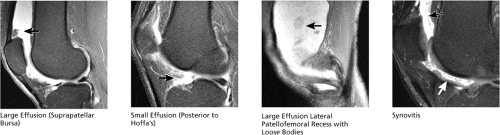 FIGURE 4.43 / JOINT EFFUSIONS. |
(9) Hoffa’s Fat Pad (Fig. 4.44)
On sagittal images Hoffa’s fat pad appears as a triangle of fat bounded superiorly by the patella, inferiorly by the tibial tubercle, and posteriorly by the anterior horns of the menisci. Irregularity of the posterior margin of Hoffa’s fat pad, with strands of joint fluid extending into its posterior aspect, indicates synovitis. Focal fat pad edema, seen at the superior lateral aspect, is indicative of a tight lateral retinaculum, which causes painful entrapment of the fat pad between the lateral patellar facet and lateral trochlear groove. The posterior aspect
of Hoffa’s fat pad is also a typical location for localized pigmented villonodular synovitis, which, given its characteristic appearance and location on MR, should not be mistaken for a sarcoma. Postoperatively, the fat pad should be inspected for scarring. Mass-like scarring suggests arthrofibrosis, a painful postoperative condition that can cause limited range of motion.
of Hoffa’s fat pad is also a typical location for localized pigmented villonodular synovitis, which, given its characteristic appearance and location on MR, should not be mistaken for a sarcoma. Postoperatively, the fat pad should be inspected for scarring. Mass-like scarring suggests arthrofibrosis, a painful postoperative condition that can cause limited range of motion.
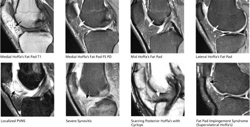 FIGURE 4.44 / HOFFA’S FAT PAD. |
(10) Plicae (Fig. 4.45)
Three varieties of plicae are common, but not present in all patients. The infrapatellar plica is depicted on midline sagittal images and appears as a U-shaped band of intermediate or dark fibers originating from the anterior intercondylar notch (anterior to the ACL), extending downward and anteriorly into Hoffa’s fat pad. Infrapatellar plicae may be associated with trochlear groove chondromalacia, and in such instances may be resected. The suprapatellar plica is seen at the superior aspect of the suprapatellar bursa on midline sagittal images. Following the suprapatellar plica medially, from midline to the medial compartment on consecutive images, the suprapatellar plica may be seen merging imperceptibly with a medial plica that traverses the medial patellofemoral recess.
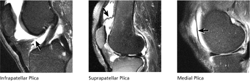 FIGURE 4.45 / PLICAE. |
Axial Plane Checklist
In the axial plane, the primary checklist structure to evaluate is (1) the cartilage covering the articular surfaces of the patella
(patellofemoral compartment). Additional structures to be evaluated include (2) the intercondylar notch, (3) the menisci, (4) collateral ligaments, and (5) joint fluid/effusion. Axial images are used to confirm pathology in ligaments, tendons, and muscles that are oriented nearly 90° to the axial plane (including the collateral ligaments and patellar tendon). In addition, specific morphologic changes in meniscal tears are confirmed on axial plane images. The proximal attachment of the ACL to the side wall of the lateral femoral condyle is also directly visualized. Joint effusions and popliteal cysts can be quantified and characterized on axial plane images.
(patellofemoral compartment). Additional structures to be evaluated include (2) the intercondylar notch, (3) the menisci, (4) collateral ligaments, and (5) joint fluid/effusion. Axial images are used to confirm pathology in ligaments, tendons, and muscles that are oriented nearly 90° to the axial plane (including the collateral ligaments and patellar tendon). In addition, specific morphologic changes in meniscal tears are confirmed on axial plane images. The proximal attachment of the ACL to the side wall of the lateral femoral condyle is also directly visualized. Joint effusions and popliteal cysts can be quantified and characterized on axial plane images.
The primary structures reviewed on axial images are in the patellofemoral compartment. The medial patellar facet, median ridge, and lateral patellar facet cartilages are clearly demonstrated. The full cranial-caudal extent of the patellar cartilage is demonstrated on consecutive axial images. It is more difficult to distinguish trochlear groove cartilage from adjacent synovium and Hoffa’s fat pad on axial images. Overlap with adjacent synovium may produce false-positive trochlear groove fissuring on axial images. The medial plica, extending from the medial capsule toward the medial patellar facet, may also be seen on axial plane images, with fluid visualized both anterior and posterior to the plica.
The patellar and quadriceps tendons are evaluated by examining consecutive cranial-to-caudal images above and below the patella. The patellar and quadriceps tendon fibers are oriented nearly 90° to the axial plane.
On superior axial images above the level of the patella, the tendons for the vastus medialis and lateralis are seen just medial and lateral to the distal quadriceps tendon. As the superior aspect of the patella comes into view, the medial and lateral retinacula are depicted, originating on the medial and lateral aspect of the patella and extending peripherally to insert on the medial and lateral femoral condyles, respectively. In transient lateral subluxation of the patella, tears of the medial retinaculum are often identified at either the patellar origin or the medial femoral condyle insertion. If transient lateral subluxation is recognized, a careful search for osteochondral defects and associated loose bodies should be performed.
(2) Intercondylar Notch (Fig. 4.49)
On superior images through the femoral condyles, the posterior intercondylar notch is shown as a U-shaped, wide, concave groove between the posterior medial and lateral femoral condyles. The origin of the ACL is seen as a thin, obliquely oriented band of fibers lying along the anterolateral aspect of the “U” formed by the posterior intercondylar notch. It is important to identify a normal ACL origin in the axial plane, since tears commonly occur at or near the ACL origin. Tears are seen as ill-defined high-intensity signal that replaces the normal thin hypointense band of ACL origin fibers. Moving in an inferior
direction through the notch, as the intercondylar notch opens anteriorly, consecutive axial images depict the ACL origin fanning out into multiple distinct dark ACL fibers that course medially and inferiorly through the intercondylar notch. The ACL ends distally as a foot-shaped insertion upon the anterolateral tibia.
direction through the notch, as the intercondylar notch opens anteriorly, consecutive axial images depict the ACL origin fanning out into multiple distinct dark ACL fibers that course medially and inferiorly through the intercondylar notch. The ACL ends distally as a foot-shaped insertion upon the anterolateral tibia.
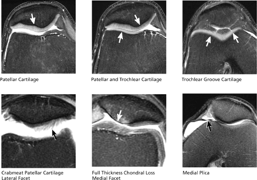 FIGURE 4.46 / PATELLOFEMORAL COMPARTMENT. |
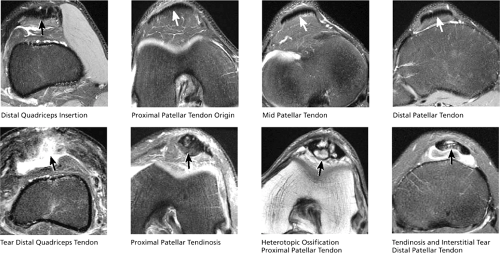 FIGURE 4.47 / QUADRICEPS AND PATELLAR TENDONS. |
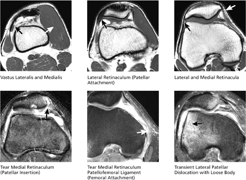 FIGURE 4.48 / MEDIAL AND LATERAL RETINACULUM. |
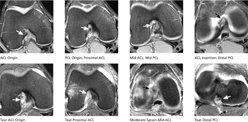 FIGURE 4.49 / INTERCONDYLAR NOTCH. |
The PCL origin can be seen two images inferior to the axial image displaying the ACL origin. The PCL origin is depicted as a broad band of fibers occupying the medial half of the “U” formed by the posterior intercondylar notch. The PCL origin is parallel to the axial plane, accounting for its broad appearance on these images. Proceeding in an inferior direction from the origin, the PCL can be seen to make a 90° turn on the next one or two images. At this point it becomes perpendicular to the axial plane and descends in the mid-posterior notch to insert on the posterior tibia. Pathologic changes in the cruciate ligaments first identified on axial plane images should be confirmed by triangulating on images of the cruciate ligaments in the coronal and sagittal planes.
(3) Menisci (Fig. 4.50)
An axial image between the femur and tibia often displays both the medial and lateral menisci. The lateral meniscus is the smaller of the two C-shaped structures along the rim of the tibial plateau. Meniscal tears found on images in other planes are confirmed on axial plane images, and correlation of tear patterns increases the degree of confidence in characterizing morphologic changes. Displaced meniscal flap fragments may be seen protruding into the coronary recess or toward the tibial spines into the intercondylar notch.
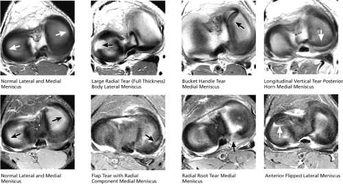 FIGURE 4.50 / MENISCI. |
The MCL and fibular collateral ligament are oriented at a 90° angle to the axial plane. At the medial margin of the medial femoral condyle, the origin of the MCL can be seen as a thin short band of fibers that course along the medial joint line to insert on the proximal tibia, anterior to the pes anserinus tendons. The LCL is depicted at the lateral margin of the lateral femoral condyle, and courses inferiorly to insert on the lateral tip of the fibula. Complete rupture of the collateral ligaments is seen as a “ghost ligament,” caused by the absence of ligament fibers on the axial image directly through the level of the tear, and is most often accompanied by prominent surrounding edema and synovitis. Synovitis and edema subjacent to the ITB is caused by the ITB friction syndrome and can also be appreciated on axial plane images.
The posterolateral corner structures adjacent to the LCL are also identified on axial images. The popliteus
tendon origin is seen just posterior and deep to the LCL origin along the lateral femoral condyle. On more inferior images, the popliteus tendon swings medially to course posterior to the posterior lateral tibial plateau. The arcuate ligament and popliteofibular ligament are seen posterior to the popliteus tendon on images above the level of the fibula.
tendon origin is seen just posterior and deep to the LCL origin along the lateral femoral condyle. On more inferior images, the popliteus tendon swings medially to course posterior to the posterior lateral tibial plateau. The arcuate ligament and popliteofibular ligament are seen posterior to the popliteus tendon on images above the level of the fibula.
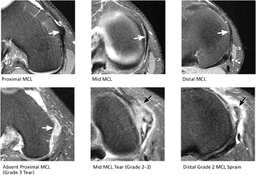 FIGURE 4.51 / MEDIAL COLLATERAL LIGAMENT. |
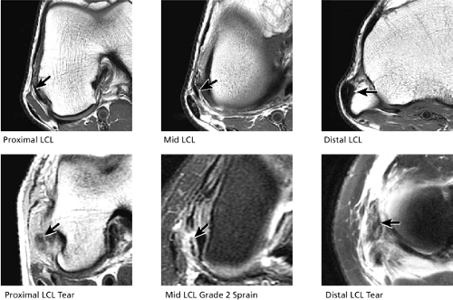 FIGURE 4.52 / LATERAL COLLATERAL LIGAMENT. |
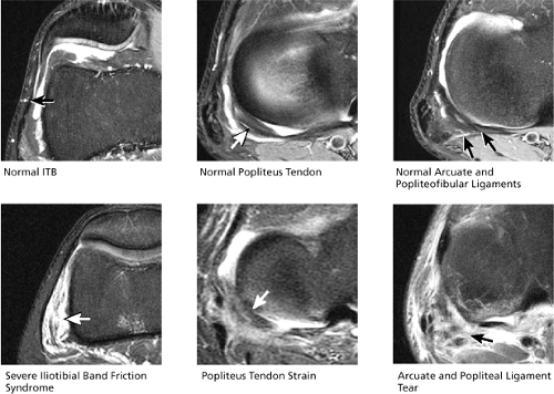 FIGURE 4.53 / ILIOTIBIAL BAND AND POSTEROLATERAL CORNER. |
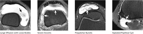 FIGURE 4.54 / JOINT FLUID. |
(5) Joint Fluid/Effusion (Fig. 4.54)
Joint effusions are evaluated on axial images to determine the size of the effusion and the character of its contents. In chondromalacia or osteochondral lesions, a careful search should be made for loose bodies within the effusion. The loose bodies may be osseous, chondral, or osteochondral in nature. Common locations for loose bodies include the medial and lateral patellofemoral recesses, the suprapatellar bursa, the popliteus tendon sheath, the posterior intercondylar notch, and within popliteal cysts. Popliteal cysts may also be found between the semimembranosus tendon and the tendon for the medial head of the gastrocnemius. Bursitis in multiple locations, including prepatellar bursitis, pes anserinus bursitis, and tibial collateral ligament bursitis, may also be depicted.
Sample MRI Report, Knee Injury
Clinical Information: Skiing injury, suspicion of ACL tear.
MRI Protocol: T1-weighted coronal images, fat-suppressed PD FSE coronal images, gradient echo sagittal images, fat-suppressed PD FSE sagittal images, T1-weighted axial images, and fat-suppressed PD FSE axial images
Findings:
Grade 1 sprain MCL (Fig. 4.55A). The LCL is intact.
Medial meniscus tear with horizontal morphology through the body segment (Fig. 4.55B). This extends partially into the posterior horn with associated flap morphology (Fig. 4.55C). Gradient echo images confirm secondary small flap fragment as well as the horizontal tear component (Fig. 4.55D). The lateral meniscus is intact.
Grade 3 tear of the proximal ACL (Fig. 4.55E). The PCL is intact.
Moderate effusion with synovitis (Fig. 4.55F). Medial plica (Fig. 4.55G) and suprapatellar plica. Prominent infrapatellar plica demonstrated.
Bone (osseous) contusion of lateral femoral condyle and posterolateral tibial plateau (Fig. 4.55H). Bone contusion of posteromedial tibial plateau (Fig. 4.55I).
Normal thickness and contour of the articular cartilage in the trochlear groove and patellar facets
Impression:
Horizontal tear of the medial meniscus, with associated secondary flap component
Grade 3 ACL tear with infrapatellar plica present
Bone contusions of lateral compartment and posteromedial tibial plateau
Medial plica and suprapatellar plica
Note: PD FSE could have been used in place of one of the T1-weighted sequences.
The Meniscus
Imaging Protocols
The traditional use of T1-weighted images and the more current use of intermediate (PD)-weighted images are considered optimal protocols for detecting meniscal lesions, which are sensitive to the T1 shortening of imbibed synovial fluid in tears and mucinous degenerations.24,25
Images acquired with a short TE (T1-, intermediate-, or GRE T2*-weighted images) are more sensitive than images acquired with a longer TE (T2-weighted images) in the detection of meniscal degenerations and tears.26 GRE T2*-weighted images, however, have the advantage of not only being sensitive to grade 1 (focal) and 2 (linear) intrasubstance degenerations and meniscal tears, but also do not rely on contrast window and level manipulation.27 In osseous contusions, however, T1-, STIR, or FS PD-weighted FSE sequences are more sensitive than heavily T2*-weighted images to subchondral marrow edema. The chronic subchondral sclerosis seen in degenerative
arthrosis and chondromalacia also is better seen on T1- than T2*-weighted images. Similarly, marrow fat (yellow marrow) signal is more clearly displayed on T1-weighted images. The rate of false-positive results in the detection of meniscal pathology is lower with GRE sequences than with conventional 2D spin-echo sequences (TR of 2,000 msec and TE of 20–80 msec).28
arthrosis and chondromalacia also is better seen on T1- than T2*-weighted images. Similarly, marrow fat (yellow marrow) signal is more clearly displayed on T1-weighted images. The rate of false-positive results in the detection of meniscal pathology is lower with GRE sequences than with conventional 2D spin-echo sequences (TR of 2,000 msec and TE of 20–80 msec).28
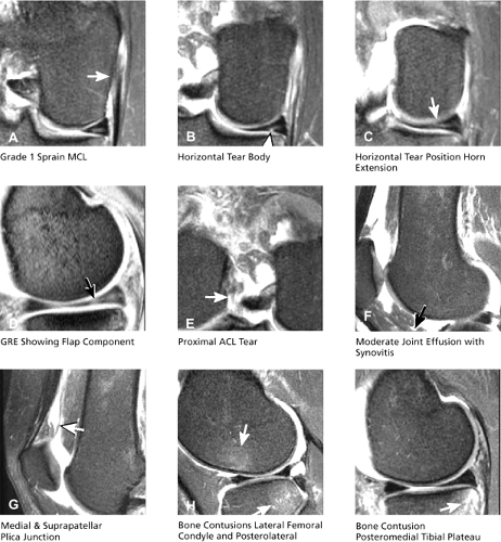 FIGURE 4.55 |
An FS PD conventional spin-echo sequence can also be used to characterize meniscal signal and avoids the potential for false-negative results inherent in relying solely on FSE sequences. Although FSE images offer the advantage of faster data acquisition, they are less sensitive to meniscal pathology than conventional T2 spin-echo pulse sequences.29 Even with a shorter ETL (≤4) to reduce image blurring, the sensitivity (65%) and specificity (96%) for meniscal pathology are decreased with FSE techniques. Rubin et al.29 have postulated that the presence of a ghosting artifact (secondary to phase differences between even and odd echoes in the echo train) or loss of meniscal signal intensity in tears secondary to an increased magnetization transfer with the FSE sequence may be responsible for the lower sensitivity of this sequence. Long-TE FSE sequences, however, may be used to partially reduce blurring and loss of meniscal signal intensity. Although useful for the evaluation of the morphology of the meniscus (especially in complex tears, postoperative partial meniscectomies, and primary repairs), reliance on FSE images alone is not recommended for the primary diagnosis of meniscal degenerations or tears. A grade 3 meniscal signal may be falsely interpreted as grade 2 signal on a PD FSE or FS PD FSE image.
There are three approaches to sagittal protocols for evaluation of the meniscus:
In one technique, the first echo of a conventional T2-weighted pulse sequence is used to produce intermediate-contrast images for the identification of meniscal lesions. A sagittal FS PD conventional spin-echo sequence generates higher signal intensity within suspected meniscal tears.
A second approach is the use of either 2D or 3D FT T2* sagittal images to demonstrate increased signal intensities in grades 1, 2, and 3 meniscal injuries.
The third approach is to use PD FSE images to identify meniscal tears. Although many protocols use a combination of PD and FS PD FSE images, image blurring may result in an underestimation of meniscal signal extension to an articular surface. Adjustments in bandwidth, resolution (matrix), and ETL can partially compensate for this limitation.
The use of IV gadolinium helps to identify the postoperative meniscus interface of meniscal implants functioning as artificial menisci. Intra-articular gadolinium is used to differentiate healing from repeated injury after primary meniscal repair or partial meniscectomy.30 A fluid-sensitive sequence (e.g., FS PD FSE) is used to demonstrate the existence of a meniscal cyst in association with a meniscal remnant.
Normal Anatomy and MR Imaging of the Meniscus
The C-shaped fibrocartilaginous menisci or semilunar cartilages are attached to the condylar surface of the tibia and provide added mechanical stability for femorotibial gliding (Fig. 4.56). The meniscus protects the articular cartilage (by acting as a buffer between femoral and tibial surfaces with loading), provides joint lubrication, and increases joint stability (by providing congruence between femoral and tibial articular surfaces). This congruence is assisted by deepening of the articular surface of the tibial plateaus to accommodate the articulation between the femoral condyles.31 The proximal or superior meniscal surface is smooth and concave, producing greater contact with the femoral condyles. The inferior meniscal surface is flat and rests on the opposing surface of the tibia.31 The peripheral aspects of the menisci are convex and thick and attach to the inside of the joint capsule. Facing the intercondylar notch, the meniscus tapers to a thin, free edge. Tibial attachments to the meniscus are made through the meniscofemoral, meniscotibial, or coronary ligaments of the joint capsule. Except for the peripheral 10% to 25% of the meniscus, which is supplied by the perimeniscal capillary plexus, the meniscus in adults is relatively avascular.32,33 In children, vascularity is already restricted to the peripheral third of the meniscus, and the inner two thirds are relatively avascular.34
Intact menisci demonstrate uniform low signal intensity on T1-, T2- (by conventional and FSE techniques), and T2*-weighted images. They are triangular in cross-section, with an outer convex curve. The apex is directed toward the intercondylar notch. The meniscus is arbitrarily divided into thirds: the anterior horn, the body, and the posterior horn. Peripherally, the meniscus has a bowtie appearance. On sagittal sections close to the intercondylar notch, the meniscus is visualized with opposing triangular shapes representing the anterior and posterior horns.
Functions of the menisci include:35
Transmission of axial and torsional forces across the joint
Cushioning of mechanical loading
Limitation of comprehensive displacement
Distribution of synovial fluid
Increasing the surface area for femoral condylar motion
Prevention of synovial impingement
Medial Meniscus
The semicircular medial meniscus has a wide posterior horn, narrows anteriorly, and has a more open C-shaped configuration than the more circular lateral meniscus. Anterior to the tibial attachment
of the ACL, the anterior horn of the medial meniscus is attached to the area of the intercondylar fossa of the tibia.31 The posterior fibers of the anterior horn attachment of the medial meniscus attach to the transverse ligament. The transverse ligament of the knee connects the anterior horns of the medial and lateral menisci. The attachment of the posterior horn of the medial meniscus is located at the posterior intercondylar fossa of the tibia.31,37,38 It can be identified between the attachment of the posterior horn of the lateral meniscus and the PCL. The medial meniscus is attached to the joint capsule along its entire peripheral circumference. The relatively limited mobility of the medial meniscal attachment to the deep layer of the MCL and capsule render the medial meniscus susceptible to injury. A small intermediate-signal-intensity bursa separates the posterior horn of the medial meniscus from the joint capsule.
of the ACL, the anterior horn of the medial meniscus is attached to the area of the intercondylar fossa of the tibia.31 The posterior fibers of the anterior horn attachment of the medial meniscus attach to the transverse ligament. The transverse ligament of the knee connects the anterior horns of the medial and lateral menisci. The attachment of the posterior horn of the medial meniscus is located at the posterior intercondylar fossa of the tibia.31,37,38 It can be identified between the attachment of the posterior horn of the lateral meniscus and the PCL. The medial meniscus is attached to the joint capsule along its entire peripheral circumference. The relatively limited mobility of the medial meniscal attachment to the deep layer of the MCL and capsule render the medial meniscus susceptible to injury. A small intermediate-signal-intensity bursa separates the posterior horn of the medial meniscus from the joint capsule.
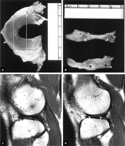 FIGURE 4.56 ● Normal anatomy of the meniscus. (A) Gross specimen of the lateral meniscus. Line 1, the sagittal plane of section through the body of the lateral meniscus; line 2, the sagittal plane of section through the anterior and body of the lateral meniscus. (B) The corresponding gross sagittal sections (1 and 2) are seen through the body (curved black arrows) and anterior and posterior horns (straight white arrows) of the lateral meniscus. The periphery or body of the meniscus has a continuous bowtie appearance. The anterior and posterior horns are oriented as opposing triangles of fibrocartilage. (C, D) The corresponding sagittal plane images (1 and 2) demonstrate the low-signal-intensity body (curved black arrows) and anterior and posterior horns (straight white arrows) of the lateral meniscus. |
Lateral Meniscus
The lateral meniscus forms a tight C shape (more circular than the medial meniscus) and is relatively symmetric in width from anterior to posterior. It accommodates the popliteus tendon posteriorly (Fig. 4.57), is separated from the lateral collateral (extracapsular) ligament, and has posterior horn attachments to the PCL and medial femoral condyle through the ligaments of Wrisberg (posterior to the PCL) and Humphrey (anterior to the PCL). The ligaments of Wrisberg and Humphrey represent branches of the meniscofemoral ligament attaching the posterior horn of the lateral meniscus to the lateral aspect of the medial femoral condyle. The lateral meniscus is relatively mobile (allowing for greater rollback on the lateral tibial plateau) and covers two thirds of the tibial articular surface.7 The anterior horn of the lateral meniscus is attached between the tibial intercondylar eminence and the anterior attachment of the ACL.31,37,38 The posterior horn of the lateral meniscus is attached between the tibial intercondylar eminence and the posterior medial meniscus. Except for the passage of the popliteus tendon, the lateral meniscus has a loose peripheral attachment to the joint capsule. There is no direct attachment of the lateral meniscus to the fibular collateral ligament or LCL. The popliteus recess allows passage to the popliteus tendon through a 1-cm hiatus in the posterolateral attachment of the lateral meniscus. The superior fascicle is seen medial to the inferior fascicle as the popliteus tendon penetrates the meniscocapsular junction. The function of the popliteal tendon attachments to the lateral meniscus is to pull the lateral meniscus posterior when the knee is flexed.39 Whereas the popliteus tendon can effectively rotate the tibia with the knee in extension, this unlocking of the knee from full extension is the reverse of the screw-home mechanism of the knee. The screw-home mechanism functions to lock the knee in extension with internal rotation of the femur relative to the tibia.40,41
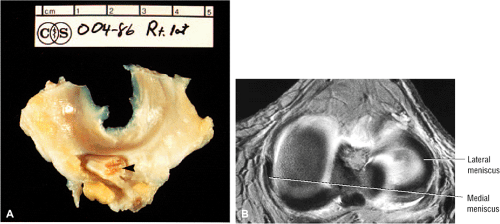 FIGURE 4.57 ● (A) Gross anatomy of the lateral meniscus and associated popliteus tendon (arrowhead). (B) Corresponding MR axial image demonstrates the C-shaped medial meniscus and teh more O-shaped lateral meniscus. The medial meniscus is more contained, which helps to explain its greater susceptibility to tearing in an ACL-deficient knee. |
Microstructure of the Meniscus
Pearls and Pitfalls
Meniscal Microstructure
Circumferential collagen fibers create normal meniscal hoop tension.
Radial (radial tie) fibers stabilize longitudinally oriented circumferential collagen fibers and also help resist meniscal extrusion.
Middle perforating collagen fibers represent a concentration of radially oriented collagen fibers in the central plane of the meniscus.
The microstructure of the fibrocartilaginous meniscus is organized so that the collagen bundles form two distinct zones, circumferential and transverse (Fig. 4.58):42
The circumferential fibers or bundles are concentrated in the peripheral third of the meniscus. Their function is to resist longitudinal loading (i.e., hoop stresses)43 by absorbing compressive forces. The meniscocapsular junction is peripheral to the circumferential zone.
In the transverse zone, radial collagen fibers bridge the circumferential zone of the meniscus peripherally toward the free edge. Radial fibers at the surface and in the midsubstance of the meniscus contribute to structural rigidity and provide resistance to longitudinal splitting.31 On cross-section, the transverse zone is divided into superior and inferior leaves by the middle perforating collagen bundle (Fig. 4.59), made up of a high concentration of radially oriented fibers. Middle perforating collagen fibers normally cannot be distinguished from adjacent meniscal tissue on MR images. Secondary vertical collagen fibers, which function as secondary stabilizers, also may be present within the transverse zone. In internal degenerations, the middle perforating collagen bundle, which may demarcate the sheer plane of the meniscus, corresponds to the location of the predominantly horizontal signal intensity seen in grade 2 menisci.
The meniscus is also characterized by three structurally distinct layers: a superficial layer with fine fibrils woven into a mesh-like patter; a surface layer deep to the superficial layer with randomly oriented collagen fibers; and a middle layer with a circumferential pattern of collagen fibers.44 Radial
fibers, also referred to as tie fibers, extend from the periphery of the middle layer into the inner rim. This framework is unique to the middle layer and allows the meniscus to resist tensile forces by converting axial loads to circumferential stresses. The resultant hoop stresses are resisted by the circumferential fibers and are transmitted to the tibia through the strong anterior and posterior meniscal attachments.45 Normal hoop tension, therefore, is significantly reduced by a radial tear that extends to the capsular margin of the meniscus.
fibers, also referred to as tie fibers, extend from the periphery of the middle layer into the inner rim. This framework is unique to the middle layer and allows the meniscus to resist tensile forces by converting axial loads to circumferential stresses. The resultant hoop stresses are resisted by the circumferential fibers and are transmitted to the tibia through the strong anterior and posterior meniscal attachments.45 Normal hoop tension, therefore, is significantly reduced by a radial tear that extends to the capsular margin of the meniscus.
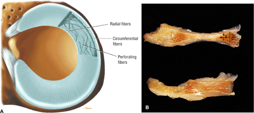 FIGURE 4.58 ● (A) Idealized structure of meniscal fibrocartilage with peripheral circumferential fibers, radial fibers, and perforating fibers. The middle layer of the meniscus functions in load transmission across the knee joint. Prominent and coarse collagen fibers directed in a parallel and circumferential direction to the meniscal periphery allow this middle layer to resist tensile forces. (Based on Miller RH. Knee injuries. In: Canale ST, ed. Operative orthopaedics, 10th ed. Philadelphia: Mosby, 2003. Chapter 43, p. 2184. ) (B) The circumferential (C) and transverse (T) zones of the meniscus. The middle perforating collagen bundle (arrow) divides the transverse zone into superior (s) and inferior (i) leaves. |
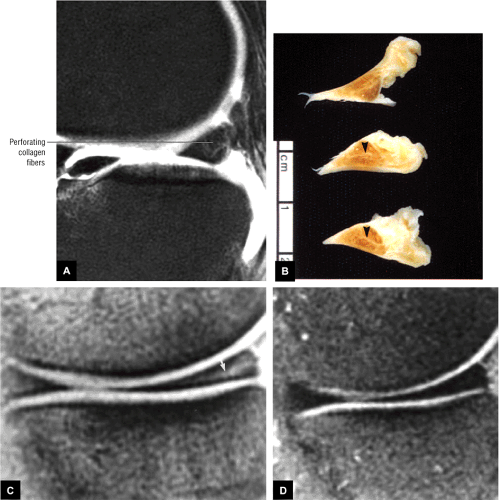 FIGURE 4.59 ● (A) Collagen network representing the radial tie fibers oriented from the circumferential peripheral zone. (B) Gross meniscal sections identify the location of the middle perforating collagen bundle and the site of preferential horizontal mucinous degeneration (arrowheads). (C) Grade 2 signal intensity (arrow) is seen in the posterior horn of the medial meniscus on a T2*-weighted image. (D) Grade 2 signal seen in C is not apparent on the corresponding FS T2-weighted FSE image. |
Vascular Supply of the Meniscus
The perimeniscal capillary plexus originates from branches of the lateral and medial geniculate arteries and supplies the periphery of the meniscus throughout its attachment to the joint capsule (Fig. 4.60).31,46 It penetrates the peripheral border of the meniscus with a circumferential network and radial branches oriented toward the center of the joint. In the adult meniscus, vascular penetrations may extend to 15% of the width of the meniscus (Fig. 4.61). On MR images, the vascular or red zone is represented by a band of peripheral hypointensity.47 Fat and vascularized connective tissue located between the meniscus and capsule should not be mistaken for the red zone of the meniscal fibrocartilage. Peripheral meniscal vascularity does not show IV contrast enhancement, whereas perimeniscal soft tissue does show enhancement adjacent to the meniscus. A vascularized synovial fringe adherent to the articular surfaces of the menisci is demonstrated throughout the peripheral attachment of the medial and lateral meniscus. This synovial reflection does not directly contribute vessels to the meniscus but may be surgically stimulated to facilitate a reparative response.
Meniscal Degenerations and Tears
Pathogenesis and Clinical Presentation
The meniscal cartilages support 50% of load transmission in the medial compartment and more than 50% in the lateral compartment.48 Clearly, the menisci are important in joint stabilization and in reduction of compressive forces acting on articular cartilage. Conservation of meniscal tissue minimizes the development of degenerative joint changes.49
The rotation of the femur against a fixed tibia during flexion and extension places the menisci at risk for injury.50 Tears involving the medial meniscus usually start on the inferior surface of the posterior horn. The lateral meniscus is more prone to transverse or oblique tears. Related hemorrhage and tearing of peripheral meniscal attachments may contribute to the pain perceived in meniscal tears. Meniscal injury may be associated with a history of twisting, squatting, or cutting.51 Abnormal shear forces, which may be generated during compression and rotation at the knee, lead to meniscal damage.
Clinical signs of meniscal pathology include:
Joint pain (at the joint line)
Giving way
Clicking
Effusions48
Locking in fixed flexion (which may occur immediately after displacement of a meniscal fragment)
Pseudo-locking (secondary to hamstring muscle spasms)51
The differential diagnosis of a meniscal tear includes osseous bone contusions (occult bony injuries), plica syndromes, popliteal tendinitis, osteochondritis and chondral lesions, loose bodies, patellofemoral pain and instability, fat-pad impingement syndrome, inflammatory arthritis, physeal or tibial spine fractures, meniscotibial ligament sprain, synovial lesions or tumors, and discoid menisci.51
MR of Meniscal Degenerations and Tears
Pearls and Pitfalls
Meniscal Degenerations and Tears
Grade 1 and grade 2 signal intensity represent intrasubstance degeneration and not fibrocartilaginous tearing.
Grade 3 signal intensity represents a meniscal tear. (The term “tear” should not be used in conjunction with grade 1 or grade 2 signal.)
A closed meniscal tear is characterized by grade 3 signal intensity that weakens or attenuates as it approaches an articular surface of the meniscus.
The articular surface of the meniscus is defined as an inferior or superior surface or the free edge apex of the meniscal fibrocartilage.
The normal meniscus demonstrates homogeneous low signal intensity on T1-, PD, T2- (conventional and FSE), GRE, and STIR-weighted images. The low signal intensity of the intact meniscus is attributed to the lack of mobile protons (water molecules within the meniscus are closely related to or absorbed within larger collagen macromolecules).26 Dephasing of hydrogen nuclei results in shortening of T2 time, contributing to the low signal intensity of meniscal tissue on all pulse sequences. In degenerations and tears of the meniscus, imbibed synovial fluid results in increased signal intensity:24
As synovial fluid diffuses through the meniscus, areas of degeneration and tears trap water molecules onto surface boundary layers, increasing the local spin density. This interaction of synovial fluid with large macromolecules in the meniscus slows the rotational rates of protons
and shortens T1 and T2 values.24 This phenomenon explains the sensitivity of T1-weighted and intermediate-weighted (i.e., PD-weighted images) in revealing meniscal degenerations and tears.
Degenerative changes and tears also result in local increases in the freedom of trapped water molecules, causing an increase in T2 times and allowing detection of increased signal intensity on short-TE sequences.26
As a result, the increased intrameniscal signal intensity seen in degeneration and tears is best visualized on short-TE images using T1, intermediate-weighted (PD), or GRE sequences. Increased signal intensity in synovial fluid gaps has been confirmed in surgically induced tears in animal models.54
In the absence of a joint effusion, meniscal degenerations and tears may actually decrease in signal intensity on T2-weighted images. On T2*-weighted GRE images, however, intrasubstance degeneration and tears generate increased signal intensities.25 Therefore, GRE sequences are extremely sensitive to the spectrum of meniscal degenerations and tears.
FSE sequences are not as useful in the evaluation of intrasubstance meniscal signal intensity and tears, even when performed with an ETL (number of echoes per TR) of 4 or less.29 FSE images may underestimate the extent or grades of MR signal intensity and thus mask the presence of a tear (see Fig. 4.59). Rubin et al.29 have attributed this blurring, which limits the usefulness of FSE images, to a ghosting artifact or an increase in magnetization transfer. Blurring is more pronounced with the use of a shorter effective TE, a longer echo train, and a smaller acquisition matrix. Short effective TE-related blurring occurs secondary to attenuation by T2 decay of later echoes (high spatial-frequency data) at the edges of k-space.
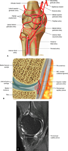 FIGURE 4.60 ● (A) The geniculate (genicular) artery anatomy, anterior anastomosis, and branches of the popliteal artery (in transparency). The vascular circle of the patellar anastomosis supplies the patella through nutrient arteries that enter at the inferior pole. The menisci receive their vascular supply primarily from the medial and lateral geniculate arteries, with the inferior and superior branches forming the perimeniscal capillary plexus within the synovium and capsular tissues. (B) Peripheral blood supply to the meniscus through vascular branches of the perimeniscal capillary plexus. This plexus receives terminal branches of all four medial and lateral geniculate arteries. (C) Sagittal FS PD FSE image displays the hyperintense perimeniscal capillary plexus posterior to the body segment or central third of the meniscus. |
To understand the significance of increased signal intensity in meniscal abnormalities, an MR grading system has been developed and correlated with a pathologic (i.e., histologic) model.24 Areas of degeneration demonstrate increased signal intensity in a spectrum of patterns or grades that are based on the signal distribution (morphology) relative to an articular meniscal surface or meniscal apex, exclusive of the peripheral capsular margin of the meniscus, which is considered nonarticular. The articular meniscal surfaces refer to the superior and inferior aspects of the meniscus opposite the distal femoral and proximal tibial articular cartilage surfaces, respectively.
Signal intensity changes include the following:
In MR grade 1, a nonarticular focal or globular intrasubstance increased signal intensity is seen (Fig. 4.62). Histologically, grade 1 signal intensity correlates with foci of early mucinous degeneration and chondrocyte-deficient or hypocellular regions that are pale-staining on hematoxylin and eosin preparations. The terms “mucinous,” “myxoid,” and “hyaline” degeneration can be used interchangeably to describe the accumulation of increased production of mucopolysaccharide ground substance in stressed or strained areas of the meniscal fibrocartilage.55,56 These changes usually occur in response to mechanical loading and degeneration. Grade 1 signal intensity may be observed in asymptomatic athletes and normal volunteers and is not clinically significant (Fig. 4.63).
In MR grade 2, a horizontal, linear intrasubstance increased signal intensity usually extends from the capsular periphery of the meniscus without involving an articular meniscal surface (Fig. 4.64). Areas and bands of mucinous degeneration are more extensive in MR grade 2 than in MR grade 1 (Fig. 4.65). Although no distinct cleavage plane or tear is observed in grade 2 menisci, microscopic clefting and collagen fragmentation may be seen in hypocellular regions of the fibrocartilaginous matrix. The low–spin-density meniscus and the middle collagen perforating bundle (which divides the meniscus horizontally into superior and inferior leaves57) cannot be differentiated in the normal knee because they both demonstrate low signal intensity. The middle perforating collagen bundle creates a neutral or buffer plane for the superior femoral and inferior tibial frictional forces and is a site for preferential accumulation of mucinous ground substance that displays grade 2 signal intensity. It also represents the shear plane of the meniscus and often is the site of horizontal
degenerative tears of the meniscus. Grade 2 signal intensity in menisci is a continuation of progressive degeneration from grade 1 and is not a discrete isolated histologic occurrence. Patients with images of grade 2 signal intensity are usually asymptomatic. Although the posterior horn of the medial meniscus is the most common location of grade 2 signal intensity, the finding of grade 2 signal intensity cannot be used as a prognostic indicator for development of grade 3 signal intensity.58 The presence of mucinous degeneration is, however, thought to represent potential structural weakening within collagen fibers, and when grade 3 signal intensity tears do develop, they are adjacent to or in continuity with areas of grade 2 meniscal degenerations. This finding is consistent with the posterior horn of the medial meniscus as the most common location for the occurrence of a meniscal tear. Although it is has been suggested that grade 2 meniscal signal intensity is a risk factor for the development of symptomatic meniscal tears, this theory has not been confirmed.26,58–64 Post-exercise studies have shown increased signal intensity in meniscal degenerations without alterations in morphology or grade of signal intensity.65 In a separate prospective study of asymptomatic football players over a 1-year period, the progression of grades of meniscal degenerations was recorded.63 Again, these preliminary findings cannot be used to predict the temporal occurrence of meniscal tears from preexisting areas of intrasubstance degenerations. The increased prevalence (24.1%) of grade 2 signal intensity in the posterior horn of the medial meniscus (as determined in a study sample of 54 asymptomatic patients with an average age of 28.5 years) is consistent with the increased frequency of grade 2 findings in this location found in cadaver menisci.24,66 Grade 2 signal intensity and discoid menisci may represent cystic areas or cavities of mucinous degeneration, which can be symptomatic
and may require treatment with partial meniscectomy. With the exception of discoid menisci, it is not common practice to treat menisci with grade 2 intrasubstance signal intensity surgically, even in a symptomatic patient. In the immature meniscus, vascular ingrowth that has been primarily reabsorbed cannot fully explain the finding of grade 2 signal intensity in a child without associated fibrocartilaginous degeneration.34 In the adult, however, the finding of increased signal intensity distinctly correlates with areas of mucinous degeneration.
A meniscus is considered MR grade 3 when the area of increased signal intensity communicates or extends to at least one articular surface (Fig. 4.66). A meniscus may contain multiple areas of grade 3 signal intensity or the entire meniscal segment (horn) may be involved, with irregular morphology. Fibrocartilaginous separation or tears can be found in all menisci with grade 3 signal intensity (Fig. 4.67). In less than 5%, these disruptions represent what has been referred to in the orthopaedic literature as confined intrasubstance cleavage or closed tears (Fig. 4.68).67 Diagnosis of closed meniscal tears requires surgical probing during arthroscopy and might be missed altogether on a routine arthroscopic examination if surface extension is not identified. Attenuation of grade 3 meniscal signal intensity as it approaches an articular surface is characteristic of closed tears. Closed tears may also represent some of the false-positive interpretations of grade 3 signal intensity when correlated with arthroscopy. Because the meniscus is an innervated structure, intrasubstance tears may present with pain in these rheologically abnormal menisci.26 In addition, false-negative correlations with arthroscopy may be related to spurious interpretation of areas of fraying or fibrillation as meniscal tears. Even without joint locking, the resultant edema and inflammation created by confined horizontal cleavage tears may be responsible for the clinical presentation of acute knee pain. Meniscal tears frequently occur adjacent to areas of intrasubstance degeneration (Fig. 4.69).
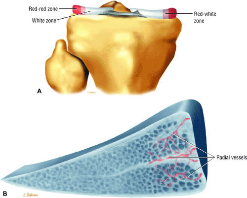 FIGURE 4.61 ● (A) The meniscal vascular supply is divided into zones of vascularity to help determine feasibility and/or success of repair. The red/red zone, the peripheral 3 mm of the meniscus, maintains an excellent blood supply. The centrally located red/white zone demonstrates variable vascularity. The red/white zone extends beyond 5 mm from the periphery and represents the avascular inner portion (including the free edge) of the meniscus. (B) Corresponding sagittal cross-section of the meniscus. The perimeniscal capillary plexus supplies the branching radial vessels, which penetrate the peripheral or outer border of the meniscus. A circumferential pattern of perimeniscal vessels is formed with the radial branches directed centrally. Peripheral vascular penetration is 10% to 30% of the width of the medial meniscus and 10% to 25% of the width of the lateral meniscus. |
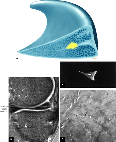 FIGURE 4.62 ● (A) Focal or globular intrameniscal degeneration (yellow) within the central shear plane of the middle collagen fibers. (B) Corresponding grade 1 signal intensity within the posterior horn of the medial meniscus on an FS PD FSE sagittal image. (C) On a cut gross section, a focus of meniscal degeneration (arrow) can be seen. (D) The corresponding photomicrograph shows hypocellularity, with decreased numbers of chondrocytes (black arrow) in pale-staining areas (white arrow). (Hematoxylin and eosin stain) |
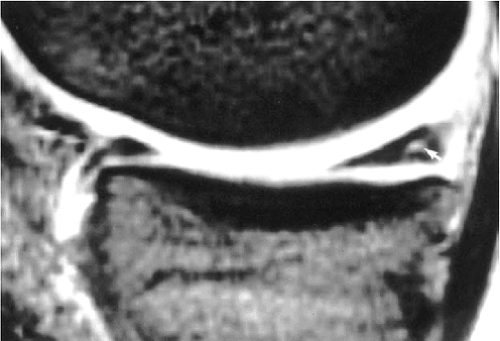 FIGURE 4.63 ● A T2*-weighted sagittal image shows grade 1 signal intensity (arrow) in the posterior horn of the medial meniscus in an athlete without medial compartment pain. |
In addition to observing increased signal intensity within tears, the morphology (i.e., size and shape) of the meniscus should be assessed when evaluating meniscal lesions. The normal meniscus measures 3 to 5 mm in height. The medial meniscus varies in width from 6 mm at the anterior horn to 12 mm at the posterior horn. The lateral meniscus is approximately 10 mm in width throughout its length.68
Regenerative chondrocytes and synovium represent attempts at meniscus healing along the tear–meniscus interface. In fact, arthroscopic rasping is performed to induce a neovascular response by abrading synovium and creating a blood supply. Synovial ingrowth in degenerative tears is thought to contribute to the development of acute and chronic pain. Hypertrophy of the synovium may also occur, secondary to joint debris in degenerative osteoarthritis, and is arthroscopically resected. Peripheral perimeniscal capillary ingrowth may be seen perforating areas of degeneration and fibrocartilaginous separation, supporting preferential healing in this location (Fig. 4.70). Acute traumatic tears have less predictable orientations and smaller areas of associated mucinous degeneration as sites for structural weakening than do degenerative tears (horizontal, cleavage, or flap tears).69 Grade 3 signal intensity is most frequent in the posterior horn of the medial
meniscus, a finding supported by the observations of increased stress and strain generated on the undersurface of the medial meniscus with femoral tibial rotations.
meniscus, a finding supported by the observations of increased stress and strain generated on the undersurface of the medial meniscus with femoral tibial rotations.
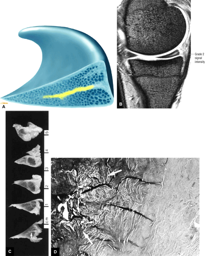 FIGURE 4.64 ● (A) Linear orientation of grade 2 intrasubstance degeneration (yellow) in the middle layer of the meniscal fibrocartilage. (B) Corresponding linear grade 2 signal intensity located in the central shear plane of the meniscus between the superior and inferior leaves of the meniscal fibrocartilage. (C) The corresponding gross section demonstrates linear mucinous meniscal degeneration (arrow). (D) The corresponding histologic study shows a focus of mucinous degeneration within the meniscal fibrocartilage (arrows). |
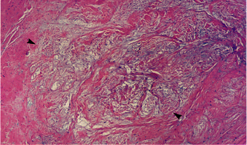 FIGURE 4.65 ● The region of mucinous degeneration (arrowheads) corresponds to grade 2 meniscal intrasubstance degeneration. (Hematoxylin and eosin stain) |
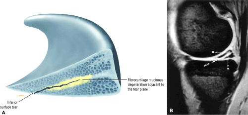 FIGURE 4.66 ● (A) Continuity of meniscal tear with intrasubstance degeneration (yellow) as an area of structural weakening of the meniscal fibrocartilage. (B) Flap tear inferior surface extension and continuity with peripheral directed meniscal hyperintensity. There are both horizontal (H) and vertical (V) components to this obliquely oriented tear. |
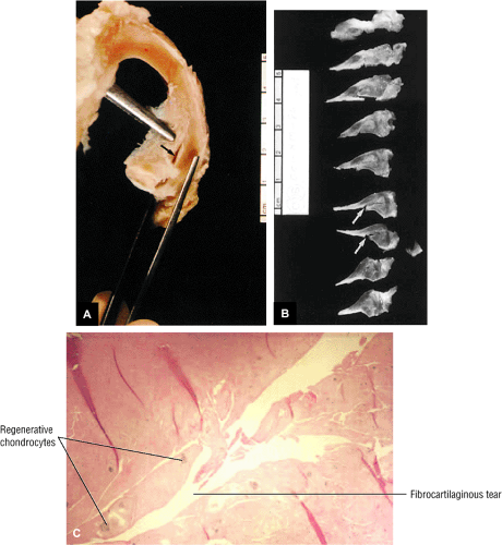 FIGURE 4.67 ● (A) On a gross specimen of the medial meniscus, an inferior surface tear (arrow) is revealed with probing. (B) Cut gross sagittal sections demonstrate the orientation of the inferior surface flap tear (arrows). (C) A photomicrograph of a grade 3 meniscal tear shows complete fibrocartilaginous separation with regenerative chondrocytes along the free edge of the torn meniscus. |
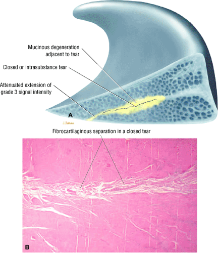 FIGURE 4.68 ● (A) Attenuated grade 3 signal intensity that weakens toward the inferior articular surface of the meniscus in a closed tear (sagittal perspective). (B) Photomicrograph demonstrates confined fibrocartilaginous separation in a closed meniscal tear. |
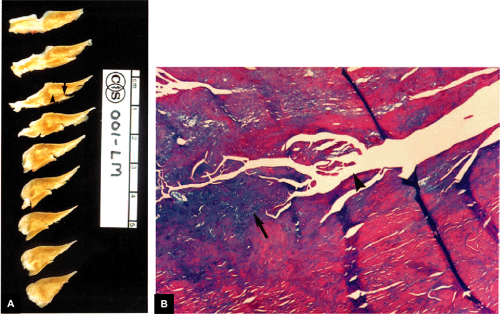 FIGURE 4.69 ● (A) A gross specimen of the posterior horn of the medial meniscus shows an inferior surface tear (arrow) adjacent to an area of intrasubstance degeneration (arrowhead). (B) The corresponding photomicrograph demonstrates a fibrocartilaginous tear (arrowhead) and surrounding (blue) mucinous degeneration (arrow). (Alcian blue stain) |
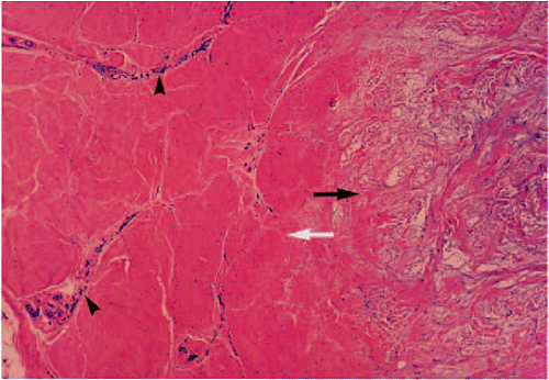 FIGURE 4.70 ● Perimeniscal capillary ingrowth (arrowheads) is directed toward an area of mucinous degeneration (black arrow). White arrow, normal adjacent meniscal tissue. |
MR makes a significant contribution in imaging of this frequently injured site. The accuracy of arthroscopy in identifying inferior surface tears of the posterior medial meniscus is reported to be as low as 45% to 65%.70,71 Furthermore, arthrographic and arthroscopic surface evaluation are insensitive to grade 1 and 2 intrasubstance degenerations as precursors to the formation of a defined meniscal tear.72 MR also detects multiple meniscal tears that may be overlooked on arthrography.
Classification of Meniscal Tears
Pearls and Pitfalls
Classification
Based on MR sagittal sections:
Vertical
Horizontal (includes the pure horizontal cleavage type)
Based on circumferential or surface anatomy:
Longitudinal (vertical or horizontal on corresponding meniscal sections)
Flap (vertical or horizontal)
Radial (vertical)
Longitudinal and flap tears can have either a primary vertical or horizontal tear pattern on corresponding sagittal images. Confusion exists because longitudinal and flap tears have been previously classified only as vertical tear types.
Radial tears, including classic radial tears and root tears, are vertical tears.
Cross-Sectional Patterns: Vertical and Horizontal Tears
The present system of classifying meniscal tears as grade 3 signal intensity relative to a meniscal articular surface does not address the anatomy of various horizontal and vertical tear patterns as identified during arthroscopic surgery of the knee.73 By using the cross-sectional anatomy of the meniscus as demonstrated on sagittal images, meniscal tears can be classified into two primary tear planes, vertical or horizontal (Fig. 4.71). However, because most meniscal tears are not exclusively perpendicular or parallel with the tibial plateau surface, tears classified as either vertical or horizontal may have secondary tear patterns (i.e., horizontal or vertical, respectively). For example, most horizontal tears extend to the inferior surface of the meniscus and do not extend to the meniscal apex as a cleavage tear.
An accurate description of the morphology and location of the tear is particularly useful in choosing between primary meniscal repair and partial meniscectomy.74 It is possible to verify meniscal tear patterns with axial images through the menisci.75
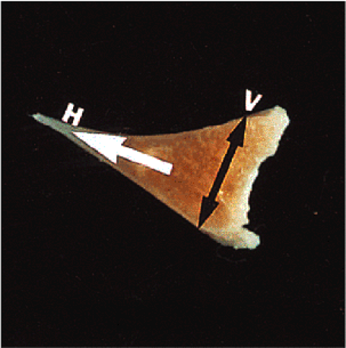 FIGURE 4.71 ● Idealized directions of horizontal (H, white arrow) and vertical (V, black arrows) tear patterns in a gross cross-section of the meniscus. |
Circumferential or Surface Patterns: Longitudinal, Radial, and Flap Tears
The surface tear pattern is created by the extension of vertical or horizontal tear planes to the articular surface of the meniscus. These surface tear types can be prospectively identified based on MR signal orientation and location as well as changes in meniscal morphology. As viewed from the surface of the meniscus at arthroscopy, and relative to its circumference, three tear patterns can be seen: longitudinal, radial or transverse, and flap or oblique (Fig. 4.72).43 A pure horizontal cleavage tear only extends to the meniscal apex and does not demonstrate superior or inferior articular surface disruption (Fig. 4.73).
Vertical tears extend to the meniscal surface as longitudinal, radial, or oblique tears. Non-cleavage horizontal tears display either longitudinal or flap surface tear patterns. When a horizontal tear remains in the plane of the middle perforating collagen bundle, it extends to the meniscal apex as a degenerative horizontal cleavage tear with similar-sized superior and inferior leaves. Although horizontal tears are sometimes referred to as “fish-mouth” tears, the description is imprecise (Fig. 4.74). Horizontal cleavage tears or flap tears with horizontal components are most frequently associated with meniscal cysts, and treatment of the underlying meniscal tear leads to involution of the cyst. Complex tears display combinations of vertical and horizontal and/or surface tear patterns (Fig. 4.75). Complex tears may thus demonstrate more than one circumferential or surface tear pattern in the same meniscus.46 For example, a radial and flap tear, a radial and horizontal tear, or a horizontal and flap tear may exist in different locations (e.g., body vs. posterior horn) in the meniscus. Complex tears may result from meniscal degeneration or be caused by significant trauma.
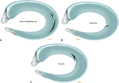 FIGURE 4.72 ● Circumferential surface tear patterns of a longitudinal tear (A), free edge radial tear (B), and a flap tear (C). The flap tear demonstrates features of a radial tear that changes direction to a longitudinal path. |
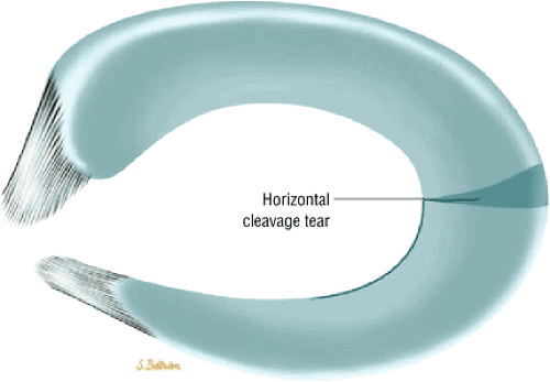 FIGURE 4.73 ● Horizontal cleavage tear extending to the meniscal apex and parallel to the tibial plateau. These tears result from excessive shear stress between femoral condylar and tibial plateau forces. |
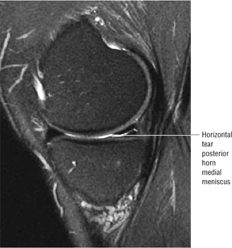 FIGURE 4.74 ● Free extension of hyperintense joint fluid within the horizontal plane of a horizontal cleavage tear parallel to the tibial plateau. The term “fish-mouth” tear describes the equal separation of the meniscal leaves (leaflets) at the inner free edge or apex of the meniscus. |
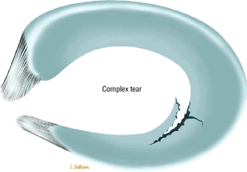 FIGURE 4.75 ● Complex meniscal tear with radial and flap components. |
Horizontal Tears
Pearls and Pitfalls
Horizontal Tears
A pure horizontal cleavage tear extends to the apex of the meniscus and results from excessive shear stress.
Longitudinal and flap tears may have a relative (not pure) horizontal orientation as viewed in the sagittal plane. However, these tear patterns occur only in association with superior or inferior leaf extension.
Horizontal cleavage tears are less common than flap tears.
The term “horizontal tear” is used to describe a horizontal cleavage tear that extends to the free edge of the meniscus in the plane of the middle collagen fibers (Fig. 4.76) with peripheral signal degeneration that may extend to the capsular periphery. In other words, horizontal tears occur in the horizontal plane and dissect circumferential collagen fibers, resulting in two separate shelves or leaves of the meniscal fibrocartilage. Although flap tears and longitudinal tears may have a relative horizontal tear vector or may demonstrate obliquely oriented grade 3 signal intensity on cross-section of the meniscus in the sagittal plane, these tears should not be classified as horizontal or pure cleavage tears. In addition, linear horizontally oriented grade 2 signal intensity may be mistaken for a complete horizontal tear.
Horizontal tears are most common within the posterior horn of the medial meniscus and are usually the result of excessive shear forces between the femoral condyle and the tibial plateau (Fig. 4.77).46 The tear involves the free edge and progresses transversely to involve the more peripheral aspects of the meniscus. On MR images, these tears demonstrate linear hyperintensity that extends to the free edge of the meniscus and is approximately parallel to the tibial articular surface. The horizontal character of the tear is equally evident on both coronal and sagittal images, but a pure cleavage tear may be difficult to appreciate on axial images because of a partial volume
effect, which can result because the signal intensity within the shear plane of the middle perforating collagen bundle is parallel to the axial plane and tibial plateau surface. A true horizontal cleavage tear should demonstrate apex extension on either coronal or sagittal images.
effect, which can result because the signal intensity within the shear plane of the middle perforating collagen bundle is parallel to the axial plane and tibial plateau surface. A true horizontal cleavage tear should demonstrate apex extension on either coronal or sagittal images.
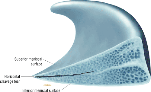 FIGURE 4.76 ● Horizontal cleavage tear divides the meniscus into superior and inferior leaflets. |
Meniscal cyst formation is commonly associated with horizontal tears (Fig. 4.78). In the presence of meniscal degeneration, tears may occur after minimal trauma. A flap tear results when there is superior or inferior extension resulting in a change of direction (into a non-horizontal plane) of the meniscal tear pattern (see Fig. 4.78). Flap tears may also develop from a radial tear with a secondary longitudinal component.
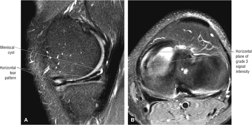 FIGURE 4.77 ● Horizontal tear with extension from the anterior horn to the posterior horn. Grade 3 signal intensity is identified within the central third or body of the medial meniscus on FS PD FSE sagittal (A) and axial (B) images. A small meniscal cyst has developed in posterior capsular tissues in continuity with the posterior horn of the medial meniscus (A). The corresponding axial image of the horizontal tear (B) demonstrates a wide area of grade 3 signal intensity within the central or middle plane of the meniscus. Because a longitudinal tear with a horizontal component would be directed to either the superior or inferior articular surface, it would not display a wide area of grade 3 signal intensity restricted to the middle or central plane extending to the meniscal apex. |
If the tear reaches the peripheral portion of the meniscus, the innervated vascular region, tenderness is typically noted at the joint line. Horizontal tears that are restricted to the free edge of the meniscus may be asymptomatic.76
Horizontal tears can usually be treated by trimming back to a stable rim. Frequently the more degenerated or smaller leaf is resected and the other leaf is preserved. In the presence of a meniscal cyst, the meniscus can be trimmed and the cyst decompressed arthroscopically.
Longitudinal Tears
Pearls and Pitfalls
Longitudinal Tears
Longitudinal tears occur in the peripheral aspect of the meniscus and are identified by peripheral grade 3 signal intensity on either coronal or sagittal images.
Longitudinal tears correspond to the long or longitudinal axis of the meniscus in the axial plane.
Longitudinal tears are not restricted to exclusively vertical tear patterns on sagittal images and may present with oblique or horizontally oriented signal (not parallel to the tibial plateau) that extends to an articular surface.
Statistically, most obliquely oriented signal intensity in the sagittal plane corresponds to flap tears, although longitudinal tears may also present with sagittal plane oblique grade 3 signal intensity. Thus, the term “oblique signal intensity” may be misleading unless used in the context of a specific circumferential or surface tear type. In practice, orthopaedic surgeons equate the term “oblique” with flap tear.
Longitudinal tears are vertical peripheral tears (Fig. 4.79) occurring along the longitudinal axis of the meniscus as viewed on axial images. This tear pattern begins in the posterior horn and advances in the direction of the circumferential collagen fibers.46 A tear viewed as longitudinal from the superior surface of the meniscus, however, may follow an either primarily vertical or horizontal course in cross-section on corresponding sagittal images (Fig. 4.80). Internal probing of a longitudinal tear during arthroscopy confirms its horizontal or vertical orientation.
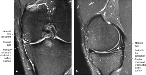 FIGURE 4.78 ● COexistence of horizontal and flap tear patterns in the posterior horn of the medial meniscus on FS PD FSE coronal (A) and sagittal (B) images. The blunting of the inferior of the meniscus with articular surface extension represents flap tear morphology. The peripheral mensical tear pattern is primarily horizontal or vertical tear patterns on corresponding sagittal images. |
Longitudinal tears extend circumferentially along the anteroposterior extent of the meniscus (parallel to the meniscal margin in the long axis). Vertical grade 3 signal intensity located within the peripheral third of the meniscus is considered to be a longitudinal tear (Fig. 4.81). Longitudinal tears may not extend through both meniscal leaflets and may be visualized only on an inferior or superior articular surface (Fig. 4.82). Thin-section axial images demonstrate linear signal intensity parallel to the long axis of the meniscus in longitudinal tears. If vertical signal intensity is located in the inner third of the meniscus, it is considered a flap tear.
Normal anatomic structures that may be mistaken for a longitudinal tear include the insertion of the transverse intermeniscal ligament and the insertion of the meniscofemoral (Humphrey’s and Wrisberg’s) ligaments to the posterior horn of the lateral meniscus. Although the popliteus tendon sheath may mimic a vertical peripheral tear of the posterior lateral meniscus, it is important to remember that vertical longitudinal tears can occur parallel to the popliteus tendon sheath (Fig. 4.83).
Longitudinal tears are most likely to occur in younger patients in an acute traumatic setting. They are usually found in the peripheral aspect of the meniscus, where there is an increased concentration of circumferential collagen fibers adjacent to the meniscal peripheral attachment. An increase in axial load (compressive force) results in radial strain and subsequent splitting of the meniscus longitudinally (between circumferential collagen fibers). The tear originates as a small longitudinal split that disrupts the posterior horn and then advances along the plane of the circumferential collagen fibers, which are split along their long axis. Multiple longitudinal tears may occur within the same meniscus. The longitudinal tear is associated with ACL and/or MCL tears, including ACL-deficient knees (Fig. 4.84). A bucket-handle or flap tear results when there is inner fragment displacement. Joint locking is usually related to pain and spasm associated with tension on the abnormally mobile fragments.
Peripheral vertical tears are successfully treated with primary meniscal repair, whereas horizontal tears that extend into avascular fibrocartilage are treated with partial meniscectomy. The peripheral extension of MR grade 3 signal intensity to the
stable meniscal rim may assist the arthroscopist in performing a partial meniscectomy but may not be appreciated at arthroscopy. This observation is consistent with the frequent appearance of grade 3 signal intensity in an asymptomatic partial meniscectomy meniscal remnant on MR.
stable meniscal rim may assist the arthroscopist in performing a partial meniscectomy but may not be appreciated at arthroscopy. This observation is consistent with the frequent appearance of grade 3 signal intensity in an asymptomatic partial meniscectomy meniscal remnant on MR.
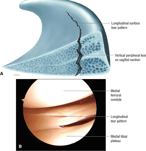 FIGURE 4.79 ● Longitudinal tear with peripheral vertical orientation through the circumferential collagen fibers. These tears result from excessive axial loads that produce radial strain that exceeds the capacity of the radial tie fibers to resist plastic deformation. Longitudinal tears are associated with ACL injuries because the meniscus may become trapped between the distal femoral condyle and the tibial plateau. (A) Lateral cross-section of a vertical longitudinal tear pattern. (B) Arthroscopic view of a medial meniscus longitudinal tear. |
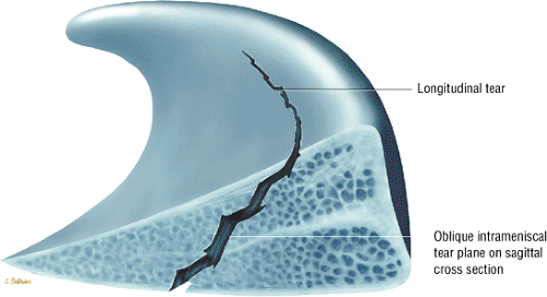 FIGURE 4.80 ● Surface longitudinal tear created by a cross-sectional pattern of both vertical and horizontal forces producing an oblique tear plane. |
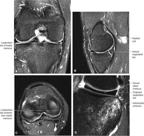 FIGURE 4.81 ● Peripheral longitudinal tear with complete superior-to-inferior surface extension on FS PD FSE coronal (A) and sagittal (B) images. (C) On an axial FS PD FSE image, the longitudinal tear can be seen coursing through the circumferential zone and following the contour of the meniscus. (D) Coronal FS PD FSE image showing a peripheral longitudinal tear in a discoid lateral meniscus. |
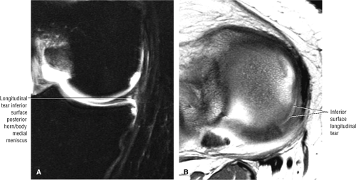 FIGURE 4.82 ● (A) Longitudinal tear with vertical peripheral morphology on FS PD FSE coronal image. (B) The longitudinal tear extends to the inferior meniscal surface and courses parallel to the long axis of the meniscus on corresponding PD FSE axial image. |
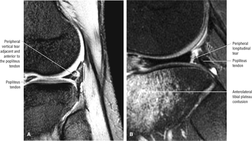 FIGURE 4.83 ● (A) Vertical longitudinal tear of the posterior horn of the lateral meniscus on a T2* GRE sagittal image. The tear is parallel and adjacent to the popliteus tendon sheath. (B) Peripheral vertical longitudinal tear of the lateral meniscus anterior to the popliteus tendon sheath on a sagittal FS PD FSE image. |
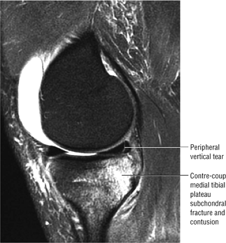 FIGURE 4.84 ● Characteristic peripheral vertical tear of the medial meniscus associated with a contre-coup medial tibial plateau fracture in an acute ACL tear (FS PD sagittal image). |
Bucket-Handle Tears
Pearls and Pitfalls
Bucket-Handle Tears
Common tear in young patients with trauma
Associated with ACL injury
An unstable meniscal fragment locks into the intercondylar notch and involves at least two thirds of the meniscal circumference.
Diagnosis of a bucket-handle tear requires identification of displaced meniscal tissue from posterior to a relative anterior coronal location. If displaced meniscal tissue is restricted to posterior coronal images, consider a displaced flap tear pattern.
A double delta sign and/or a double PCL sign are sagittal MR findings of a displaced bucket-handle tear.
A displaced longitudinal tear of the meniscus, usually the medial meniscus, is called a bucket-handle tear because the separated central fragment resembles the handle of a bucket (Fig. 4.85).24 The remaining larger peripheral section of the meniscus is the bucket. Vertical longitudinal tears are further classified as single vertical longitudinal tears, displaced bucket-handle type tears, broken bucket-handle tears, and double and triple vertical longitudinal bucket-handle tears.77 MR images further show that a bucket-handle tear may originate from either primary vertical or horizontal longitudinal tear patterns. Bucket-handle tears frequently occur in young patients secondary to significant trauma.78
Medial meniscus bucket-handle tears
Medial meniscus bucket-handle tears are three times more frequent than bucket-handle tears involving the lateral meniscus. The central fragment of a bucket-handle tear may be completely displaced into the intercondylar notch or, as may occur with a shorter tear of the posterior meniscus, may be only partially displaced. A bucket-handle tear effectively reduces the width of the meniscus, and peripheral sagittal images fail to demonstrate the normal bowtie configuration of the body of the meniscus. The remaining anterior and posterior horns are often hypoplastic or truncated, with or without increased internal signal intensity. In the normal medial meniscus without tear, the posterior horn is wider and thus has greater height than the anterior horn. Foreshortening of the posterior horn of the medial meniscus without history of previous partial meniscectomy is associated with bucket-handle morphology.
On coronal images, a displaced meniscal fragment can frequently be identified within the intercondylar notch.79 On sagittal images (provided the fragment displaces into the intercondylar notch), the displaced fragment of a bucket-handle tear is seen as a low-signal-intensity band parallel and anterior to the PCL.80 In simple and complex bucket-handle tears, axial images show the relation of the displaced tear to the remaining meniscus in a single section (Fig. 4.86).
The double PCL sign refers to visualization of the displaced meniscal fragment anterior to the PCL in the intercondylar notch.81 The double delta sign refers to visualization of flipped inner meniscal fragments adjacent (posterior) to the anterior horn of the donor site (Fig. 4.87). The double delta sign is produced by two triangular structures adjacent to each other anteriorly. The free edge of the native anterior horn is deformed (blunted) at the anterior tear site of the bucket-handle tear, whereas the displaced meniscal tissue has a well-defined free edge and may be mistaken for the native anterior horn meniscus. In complex bucket-handle tears, displacement of an anteriorly based flap may widen the gap anterior to the bucket-handle fragment (Fig. 4.88).
As a result of this anterior displacement, there is a relative lack of posterior horn notch fragments, as is commonly seen in lateral bucket-handle tears. Although a displaced posterior horn or body flap tear may mimic a bucket-handle tear on posterior coronal images, a true bucket-handle tear can be seen on multiple cross-sectional coronal images from posterior to anterior. Therefore, the presence of a third structure (separate from the ACL and PCL) within the intercondylar notch must be documented on more than a single posterior coronal image to fulfill the criteria of a bucket-handle tear. A less common occurrence
is the finding of bucket-handle tears in both the medial and lateral compartments. In this situation four meniscal fragments can be seen in the coronal plane (Fig. 4.89). Three separate meniscal fragments can be seen anterior to the PCL on sagittal plane images when the anterior tear site of the bucket-handle tear and the displaced notch fragments are co-linear.
is the finding of bucket-handle tears in both the medial and lateral compartments. In this situation four meniscal fragments can be seen in the coronal plane (Fig. 4.89). Three separate meniscal fragments can be seen anterior to the PCL on sagittal plane images when the anterior tear site of the bucket-handle tear and the displaced notch fragments are co-linear.
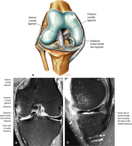 FIGURE 4.85 ● (A) Displaced fragment of a medial meniscus bucket-handle tear lodged within the intercondylar notch. The intercondylar notch fragments are identified anterior to the PCL. (B) Displaced intercondylar notch fragment representing an extra (in addition to the ACL and PCL) structure within the intercondylar notch. (C) Effectively reduced width of the body of the meniscus serving as the donor site for the bucket-handle fragment. |
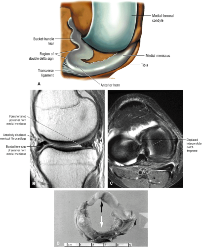 FIGURE 4.86 ● Bucket-handle tear with the peripheral meniscus shown as the source of the bucket-handle fragment. (A) The anterior double delta sign is created by the location of the anterior portion of the displaced fragment adjacent (posterior) to the native anterior horn of the meniscus. (B) Sagittal PD FSE image showing the anterior double delta sign of a medial meniscus bucket-handle tear. Note the foreshortened posterior horn on this sagittal image. (C) An axial FS PD FSE image of the bucket-handle tear. (D) A gross specimen demonstrates a displaced longitudinal bucket-handle tear (black arrows) from the medial meniscus (white arrow). |
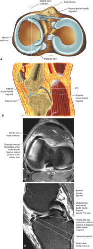 FIGURE 4.87 ● Double delta and double PCL signs. (A) Axial perspective color illustration showing the displaced fragment in proximity and posterior to the anterior horn segment. The central portion of the bucket fragment is responsible for the double PCL sign. (B) Corresponding sagittal section with double delta and double PCL fragments. (C) Effectively reduced width of the body of the meniscus serving as the donor site for the bucket-handle fragment. Native anterior horn of the medial meniscus is characteristically anterior to the displaced notch fragment on direct axial image. (D) Double PCL, double delta, and transverse ligament all on one single sagittal image. |
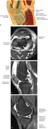 FIGURE 4.88 ● (A) Increased gap between anterior horn and bucket-handle fragments in complex bucket-handle tear. (B-D) Complex medial bucket-handle tear with three separate displaced meniscal fragments anterior to the posterior horn (D) (B, axial FS PD FSE; C, sagittal FS PD FSE; D, sagittal FS PD FSE). D is medial or peripheral to C. |
Lateral meniscus bucket-handle tears
The lateral meniscus may also be the site of bucket-handle tears in which the body of the lateral meniscus is displaced into the intercondylar notch (Fig. 4.90).82 In lateral meniscus tears there may be greater anterior displacement of posterior horn tissue than is seen in medial bucket-handle tears (Fig. 4.91). As with medial meniscus bucket-handle tears, the native anterior horn fragments usually have a blunted free edge, whereas the more posteriorly located (relative to the anterior horn) flipped or displaced fragment may be mistaken for the normal anterior horn segment (Fig. 4.92). The proximity of a lateral meniscus fragment to the ACL should be carefully evaluated on both coronal and sagittal planes to avoid underdiagnosis (Fig. 4.93).
Patients with bucket-handle tears may present with a locked knee or may lack full extension. These tears may also be associated with ACL injuries,78 and single or multiple flaps of meniscal tissue may be generated. As previously discussed, bucket-handle tears may start as a longitudinal tear with a primarily horizontal tear pattern. A displaced vertical component subsequently generates a bucket-handle morphology. This pathogenesis is supported by the finding that residual peripheral horizontal grade 3 signal intensity may persist after a partial meniscectomy performed to treat a bucket-handle tear. More commonly, bucket-handle tears are displaced vertical, longitudinal tears. Patients may also present with pain as the displaced free edge of the meniscus subluxes between the femoral condyle and tibial plateau into the intercondylar notch.46 Tenderness may be present at the anterior margin of the displaced or mobile meniscus, adjacent to Hoffa’s fat pad, because the peripheral meniscal nerve fibers are under tension at the apex of the tear. The posterior spring sign, a lack of full extension probably secondary to pain and muscle spasm, usually disappears with examination under anesthesia, which typically demonstrates return of the knee to full extension.
Treatment for nonseparated symptomatic tears is a partial meniscectomy, although meniscal repair may be undertaken in some double bucket-handle tears. Excision of a displaced fragment of a bucket-handle tear is considered in the following circumstances:
There is a significant radial split tear in the displaced bucket-handle component.
The meniscal rim size is 5 mm or greater, placing the tear clearly in the avascular zone of the meniscus.
The tear is chronic, with deformed (twisted) morphology77
Radial or Transverse Tears
Pearls and Pitfalls
Radial or Transverse Tears
There are three subtypes of classic radial tears (more common in lateral meniscus):
Anterior horn-body junction
Body
Posterior horn-body junction
Root tears are more common in the posterior horn of the medial meniscus.
Classic radial tears are commonly associated with horizontal tears in the lateral meniscus and flap tears in the medial meniscus.
MR findings in classic radial tears include (1) a blunted anterior horn and elongated posterior horn body segment; (2) a blunted posterior horn in association with an elongated anterior horn body segment; or (3) free edge increased signal intensity or blunting restricted to the middle third of the meniscus that does not involve blunting of the anterior or posterior horns or elongation of body segment.
Root tears are defined by abrupt loss or blunting of posterior horn meniscal tissue on posterior coronal images adjacent to the root meniscal insertion. A ghost meniscus or relative absence of posterior horn meniscal fibrocartilaginous tissue is characteristic of root tears on sagittal images located adjacent to the intercondylar notch.
Radial or transverse tears are defined as vertical tears perpendicular to the free edge of the meniscus and are subdivided into classic radial tears and root tears. Classic radial tears are further subdivided by location within the lateral meniscus. Both classic and root tears may involve either the medial or lateral meniscus. Classic radial tears, however, are more common in the lateral meniscus. Root tears are more frequently observed involving the posterior horn or the medial meniscus.
Classic radial tears
There are three recognized locations of classic radial tears. The most common classic radial tear involves the anterior horn-body junction of the free edge of the lateral meniscus (Fig. 4.94). Along the free edge of the meniscus there is a relatively higher concentration of radially oriented collagen bundles and thinning out of circumferential longitudinal fibers, increasing the likelihood of tears at this location. The position of the lateral aspect of the lateral meniscus contributes to the increased stiffness of radially oriented fibers at the middle perforating collagen bundle and to their susceptibility to shear stresses. Less commonly, classic radial tears present along the middle third of the meniscus (appearing as free edge blunting) or at the posterior horn-body junction of the meniscus (Fig. 4.95).
Because the sagittal plane sections the meniscus perpendicular to the free edge orientation of the tear, the only evidence of a radial tear on sagittal images may be increased signal intensity (focal grade 3) on one or two peripheral sections. On these images, the classic or common radial tear is characterized
by blunting of both the anterior horn-body junction and blunting and elongation of the posterior horn body segment. Because the tear plane is in the anterior third of the meniscus, the posterior horn body segment is seen as exaggerated or elongated, a finding characteristic of radial tears.83 The blunted anterior horn varies in size relative to the elongated posterior horn body segment, based on the location of the sagittal plane of section. The more closely the plane of section approximates the free edge of the meniscus, the more prominent the blunted anterior horn segment (Fig. 4.96). On sagittal images of a radial tear located at the junction of the posterior horn and body, the anterior horn body segment is elongated or exaggerated in anterior to posterior length.
by blunting of both the anterior horn-body junction and blunting and elongation of the posterior horn body segment. Because the tear plane is in the anterior third of the meniscus, the posterior horn body segment is seen as exaggerated or elongated, a finding characteristic of radial tears.83 The blunted anterior horn varies in size relative to the elongated posterior horn body segment, based on the location of the sagittal plane of section. The more closely the plane of section approximates the free edge of the meniscus, the more prominent the blunted anterior horn segment (Fig. 4.96). On sagittal images of a radial tear located at the junction of the posterior horn and body, the anterior horn body segment is elongated or exaggerated in anterior to posterior length.
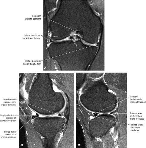 FIGURE 4.89 ● (A) Bicompartmental bucket-handle tears producing four separate meniscal fragments on coronal image. Characteristic double delta sign is demonstrated on corresponding medial (B) and lateral (C) compartment sagittal images. |
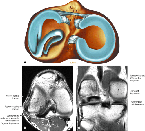 FIGURE 4.90 ● (A) Complex bucket-handle tear with greater posterior horn body involvement. Axial (B) and coronal (C) PD FSE images show a complex lateral bucket-handle tear with a posterior notch fragment displacement producing redundant folding of the meniscus. |
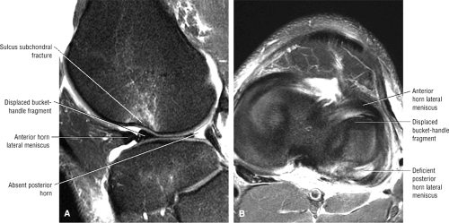 FIGURE 4.91 ● (A) Sagittal FS PD FSE image showing a typical anterior flap lateral meniscus fragment displaced posterior to the native anterior horn. Contusion and deformity of the sulcus resulted from an associated ACL tear. (B) Axial FS PD FSE image displaying anterior displacement of a large posterior body fragment in a characteristic lateral meniscus bucket-handle pattern. |
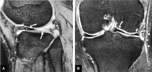 FIGURE 4.92 ● Bucket-handle tear of the lateral meniscus. (A) Sagittal T2*-weighted and (B) FS T2-weighted FSE coronal images show an anteriorly displaced posterior horn of the lateral meniscus (large curved arrow). Note the absence of meniscal tissue in the expected location (the posterior horn of the lateral meniscus) (large straight arrow). This deformity, with blunting of the apex (small straight arrow) of the anterior horn segment (small curved arrow), is commonly seen as a result of compression by the displaced posterior horn. |
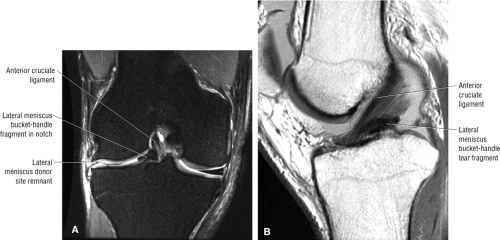 FIGURE 4.93 ● Coronal FS PD FSE (A) and sagittal PD FSE (B) images of a lateral bucket-handle tear fragment displacing the ACL from lateral to medial. |
Corresponding coronal images demonstrate the radial tear site in the anterior or posterior horn-body junction without posterior root involvement unless an associated root tear is also present (Fig. 4.97). Radial tears of the middle third of the meniscus are characterized by free edge blunting on central coronal images and by subtle blunting of the apex of the meniscus. These images may not demonstrate areas of increased signal intensity.
Disruption of hoop containment is associated with extension of radial tears to involve the longitudinal fibers of the circumferential zone. This disruption of the normal hoop tension effect results in peripheral subluxation or partial extrusion of the body of the meniscus (Fig. 4.98).84
The classic radial tear may present as a complex tear in association with a secondary horizontal cleavage tear, especially in the lateral meniscus (Fig. 4.99). This tear propagates anteriorly or posteriorly into the circumferential fibers and results in a split radial variant. These subtypes of classic radial tears are more common in the lateral meniscus but may be seen in the medial meniscus as well. In complex radial tears of the medial meniscus, the radial tear is frequently seen in association with a flap tear of the posterior horn of the medial meniscus, characterized by relative deficiency of the free edge of the inferior leaf of the posterior horn.
Classic radial tears may also be characterized as incomplete (the tear is restricted to the free edge of the meniscus) or complete (the tear extends peripherally to the meniscal synovial rim). Peripheral extension with a change in the direction of the tear transforms a radial tear into a flap tear pattern.
Root tears
The root tear subtype of radial tear can occur in either the medial or lateral meniscus, although it is more common in the medial meniscus, where it is thought to represent a degenerative tear.46 The meniscotibial attachment of the posterior horn is a typical location for this tear type (Fig. 4.100), as is the junction of the meniscus-root interface (Fig. 4.101). Displacement of the root tear produces a relative absence of posterior horn meniscal fibrocartilage on sagittal images. Diffuse increased signal intensity seen on one or two sagittal images of these displaced root type radial tears represents the so-called ghost meniscus (Fig. 4.102). Corresponding posterior coronal images demonstrate abrupt blunting of the normal meniscotibial attachment and foreshortening of the meniscus toward the posterior aspect of the intercondylar notch (Fig. 4.103). The residual meniscofemoral ligament may be mistaken for residual posterior horn tissue in the lateral compartment. The root tear of the posterior aspect of the lateral meniscus may present with either
a ghost meniscus appearance of the posterior horn on sagittal images or blunting of the lateral meniscus on posterior coronal images adjacent to the intercondylar notch.
a ghost meniscus appearance of the posterior horn on sagittal images or blunting of the lateral meniscus on posterior coronal images adjacent to the intercondylar notch.
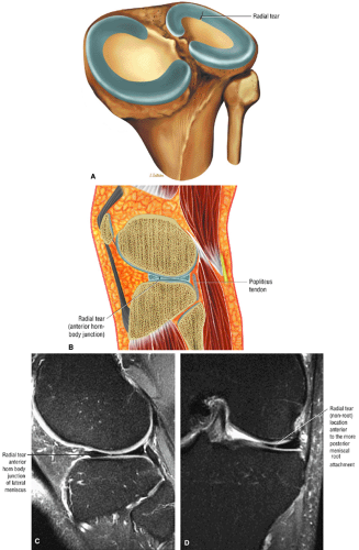 FIGURE 4.94 ● (A) Free edge radial tear at the junction of the anterior horn and body of the lateral meniscus. (B) Corresponding sagittal section produces the characteristic blunted foreshortened anterior horn and elongated components of the meniscal body and posterior horn. (C) Classic radial tear involving the anterior horn-body junction of the lateral meniscus. The blunted free edge of the anterior horn and elongated posterior horn are shown on this FS PD FSE sagittal image. (D) The corresponding coronal FS PD FSE image at the level where the femoral condyles fuse identifies the radial tear. |
As with bucket-handle tears, lateral meniscus root tears are associated with ACL tears. Displacement of these root tears may result in flipping of meniscal fragments into the posterior aspect of the intercondylar notch. These flipped meniscal fragments are best appreciated on posterior coronal images. Large radial tears (>50% of the meniscal width) or root tears are also associated with significant (>3 mm) meniscal extrusion relative to the tibial plateau.84
Clinically, tears 3 mm or less in length may be asymptomatic, whereas tears greater than 5 mm are more likely to produce symptoms.78 Symptomatic tears can be treated by trimming the anterior and posterior leaves adjacent to the tear site. As mentioned above, some radial tears are associated with more complex meniscal tears, such as a vertical longitudinal tear or a peripheral horizontal cleavage component. We prefer not to use the term “parrot-beak” tear, which is sometimes used to describe a free edge tear with both vertical and horizontal components, to describe a nondisplaced flap tear. Flap tears (see below) usually originate from a free edge radial tear that subsequently changes direction, thus creating the meniscal flap. This flap may be displaced toward the notch or become inverted and extruded peripherally. Root tears should be repaired unless there is unstable meniscal tissue separated from its peripheral attachment.
Flap Tears
Pearls and Pitfalls
Flap Tears
Flap tears usually result from extensions of radial or horizontal cleavage tears and represent the most common clinical tear type.
Vertical grade 3 signal intensity in the inner one third to one half of the meniscus and relative deficiency of the inferior surface of the meniscus are the most common findings in flap tears.
Flap tears may demonstrate menisical extrusion into the coronary recess of a meniscotibial ligament on coronal images. Reactive tibial plateau marrow edema is associated with these extrusions.
Oblique meniscal signal intensity on sagittal images does not necessarily equate with flap tear morphology (see criteria for for flap tear diagnosis).
Flap tears, large radial tears (including root tears), and complex tears are associated with major (>3 mm) meniscal extrusion.
Displaced flap tears of the posterior horn of the lateral meniscus are associated with tears.
A flap tear, which represents a composite of a longitudinal and a radial tear, starts on the free edge of the meniscus
and curves o.bliquely into the meniscal fibrocartilage (Fig. 4.104). These tears may also be referred to as oblique tears. Flap tears represent the most common meniscal tear type and are frequently associated with oblique signal intensity on sagittal plane meniscal cross-section (e.g., grade 3 signal intensity commonly extending to the inferior surface of the posterior horn of the medial meniscus). Flap tears may display either a primary vertical or horizontal tear pattern. Identification of obliquely oriented grade 3 meniscal signal on sagittal images does not necessarily indicate the presence of a flap or oblique tear, since longitudinal tears may also appear as an oblique course of grade 3 signal intensity extending to the meniscal surface. Unlike longitudinal tears, flap tears involve the inner one third to one half of the meniscus, with superior or inferior leaf extension creating the mobile limb or flap of fibrocartilage. In contrast, longitudinal tears are more likely to involve the peripheral third of the meniscus, where there is a greater concentration of circumferential fibers.
and curves o.bliquely into the meniscal fibrocartilage (Fig. 4.104). These tears may also be referred to as oblique tears. Flap tears represent the most common meniscal tear type and are frequently associated with oblique signal intensity on sagittal plane meniscal cross-section (e.g., grade 3 signal intensity commonly extending to the inferior surface of the posterior horn of the medial meniscus). Flap tears may display either a primary vertical or horizontal tear pattern. Identification of obliquely oriented grade 3 meniscal signal on sagittal images does not necessarily indicate the presence of a flap or oblique tear, since longitudinal tears may also appear as an oblique course of grade 3 signal intensity extending to the meniscal surface. Unlike longitudinal tears, flap tears involve the inner one third to one half of the meniscus, with superior or inferior leaf extension creating the mobile limb or flap of fibrocartilage. In contrast, longitudinal tears are more likely to involve the peripheral third of the meniscus, where there is a greater concentration of circumferential fibers.
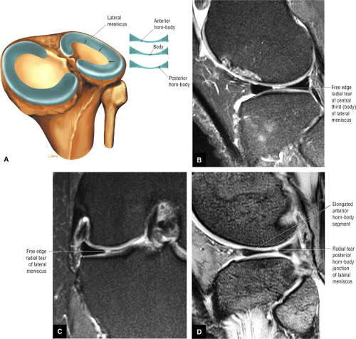 FIGURE 4.95 ● (A) Common locations for free edge radial tears include the anterior horn-body junction, the body (central third of the meniscus), or the posterior horn-body junction. A classic (non-root) radial tear pattern is located at the free edge of the body of the lateral meniscus on FS PD FSE sagittal (B) and coronal (C) images. Radial tears are typically visualized on peripheral sagittal images or coronal images through sectioning the body or middle third of the meniscus. Note the characteristic free edge blunting in the coronal plane image. (D) Classic (non-root) radial tear involving the posterior horn-body junction on a FS PD FSE sagittal image. The anterior horn body segment has an elongated morphology as the radial tear involves the posterior horn-body junction. |
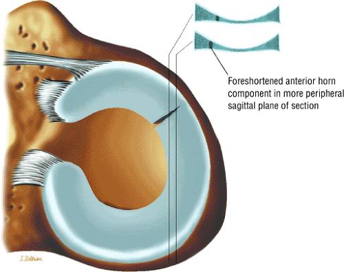 FIGURE 4.96 ● The size of the anterior component of a classic radial tear varies depending on the location of the sagittal plane of section. Further foreshortening of the anterior horn-body junction occurs with a more peripheral plane of section (bottom inset). |
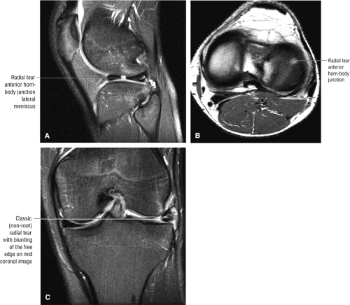 FIGURE 4.97 ● Classic lateral meniscus radial tear at anterior horn-body junction on an FS PD FSE sagittal image (A), a PD FSE axial image (B), and an FS PD FSE coronal image (C). The resultant blunting of both the anterior and posterior horns with posterior horn elongation is typical of the involvement of the body or middle third of the meniscus in a radial tear. A blunted meniscus on mid-coronal plane images (at or anterior to the plane of the MCL) is also characteristic. |
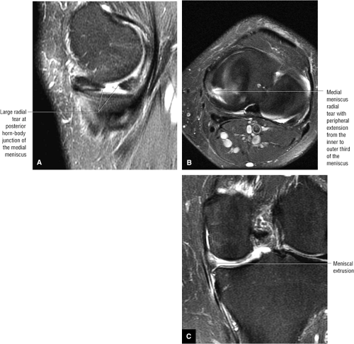 FIGURE 4.98 ● (A) Extensive radial tear of the posterior horn-body junction of the medial meniscus on an FS PD FSE sagittal image. (B) Extension of the radial tear into the peripheral circumferential zone on an FS PD FSE axial image. (C) Extrusion of the meniscus results from loss of normal meniscal hoop tension. |
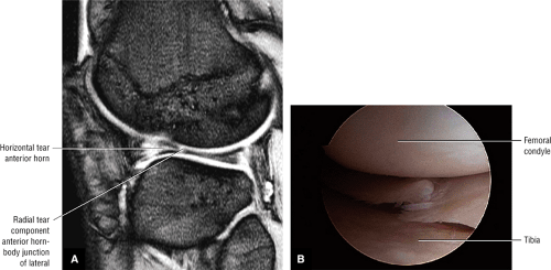 FIGURE 4.99 ● (A) T2* GRE sagittal image displaying a combination of radial and horizontal tear patterns extending to the anterior horn-body junction of the lateral meniscus. The horizontal tear primarily involves the anterior horn segment. (B) Arthroscopic view of a radial tear extending into a horizontal cleavage component. |
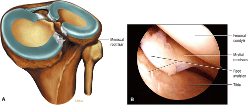 FIGURE 4.100 ● (A) Medial meniscal root tear avulsion occurring directly from the osseous tibial attachment site. (B) Arthroscopic view of medial meniscus root avulsion. |
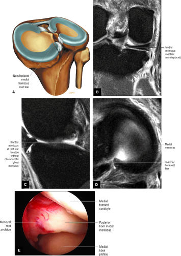 FIGURE 4.101 ● (A) Color illustration of nondisplaced root tear of the posterior horn medial meniscus. Posterosuperior perspective. Coronal (B), sagittal (C), and axial (D) images of a posterior horn root tear at the meniscal root attachment without associated displacement at the tear site. A ghost (absent) meniscus is not appreciated on sagittal images. (E) Corresponding arthroscopic view of meniscal root tear. |
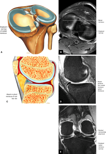 FIGURE 4.102 ● Displaced posterior horn root tear of the medial meniscus on axial illustration (A) and FS PD FSE axial images (B). Corresponding “ghost” meniscus is demonstrated on a sagittal illustration (C) and FS PD FSE sagittal image (D) through fluid-filled tear gap. Note residual meniscal tissue still attached to the meniscotibial attachment on coronal FS PD FSE image (E). |
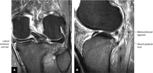 FIGURE 4.103 ● Lateral meniscal root tear on FS PD FSE coronal (A) and sagittal (B) images. The hypointense meniscofemoral ligament is identified posterior to the root tear on the sagittal image (B). |
The use of the term “flap tear” is at present somewhat confusing. Some classification systems describe a partial cleavage tear with a mobile flap of meniscal tissue as a subtype of horizontal tear. It is more accurate, however, to use the term “flap tear” to describe a distinct tear pattern and not as a subtype of or a synonym for a horizontal tear. In addition, although the terms “flap tear” and “oblique tear patterns” are interchange able, most orthopaedic surgeons consider “flap tear” to be the proper terminology. Radiologists, therefore, should avoid using these terms to describe obliquely oriented signal intensity unless a flap tear is directly confirmed and visualized on axial images or is correctly diagnosed using specific criteria for flap tears. We have developed such criteria for the prospective diagnosis of flap tear patterns based on the characteristic morphology of signal intensity and meniscal morphology in the sagittal plane. The criteria have been expanded to include coronal images to take into account the characteristic finding of meniscal extrusion into the coronary recess.
The criteria for diagnosis of a flap tear based on sagittal images include:
A vertical tear encompassing the inner third of the meniscus, either coapted (Figs. 4.105 and 4.106) or non-coapted (Fig. 4.107)
Relative deficiency of the inner third of the inferior meniscal surface with associated blunting of the remaining inferior leaf (Fig. 4.108)
A blunted free edge of the meniscus with displaced meniscal tissue inferior to the periphery of the meniscus (Fig. 4.109)
A change in the slope of the superior surface of the meniscus, indicating a change in the direction of the tear that creates the flap (Fig. 4.110)
In addition, extrusion of a portion of the meniscus into the coronary recess below the joint line is seen on coronal images (Figs. 4.111 and 4.112). The displaced flap in the coronary recess is also visualized on peripheral sagittal images with hypointense meniscal tissue below the level of the joint line or tibial plateau deep to the MCL on peripheral medial images (Fig. 4.113).84,85
In addition to the location of vertical signal intensity in the inner one third to one half of the meniscus, relative deficiency
of the inner margin of the inferior leaf of the meniscus is a characteristic finding in flap tears. Although flap tears most commonly involve the posterior horn of the medial meniscus, they may also be seen in the lateral meniscus. As the mobile flap rotates it may produce either double-decker (see Fig. 4.112) or stacked leaflet meniscal morphology, or it may extend into the meniscofemoral or meniscotibial recess (Fig. 4.114). When associated with ACL injuries, complex flap tears may displace posteriorly into the intercondylar notch (Fig. 4.115).86 Complex flap displacement and rotation of the posterior horn of the lateral meniscus may be mistaken for ACL ligamentous tissue (double ACL sign).
of the inner margin of the inferior leaf of the meniscus is a characteristic finding in flap tears. Although flap tears most commonly involve the posterior horn of the medial meniscus, they may also be seen in the lateral meniscus. As the mobile flap rotates it may produce either double-decker (see Fig. 4.112) or stacked leaflet meniscal morphology, or it may extend into the meniscofemoral or meniscotibial recess (Fig. 4.114). When associated with ACL injuries, complex flap tears may displace posteriorly into the intercondylar notch (Fig. 4.115).86 Complex flap displacement and rotation of the posterior horn of the lateral meniscus may be mistaken for ACL ligamentous tissue (double ACL sign).
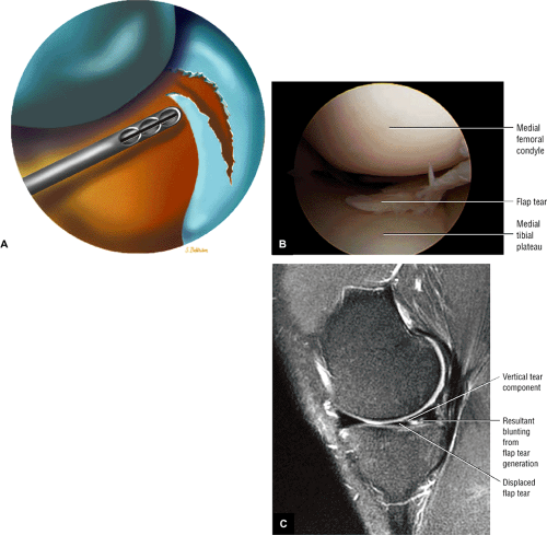 FIGURE 4.104 ● (A) Illustration depicting a flap tear at arthroscopy. (B) Vertical inner-third tearing produces an anteriorly displaced meniscal fragment, creating the flap identified at arthroscopy. (C) Blunting of the free edge of the meniscus is shown on a sagittal FS PD FSE image. Corresponding coronal plane diagnosis of a flap tear usually requires evidence of meniscal displacement into the meniscofemoral or meniscotibial recess. |
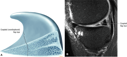 FIGURE 4.105 ● Coapted flap tear with vertical tear morphology involving the inner third of the medial meniscus as seen on a sagittal color illustration with superior and cross-sectional view of the meniscus and flap tear (A) and a sagittal FS PD FSE image (B). |
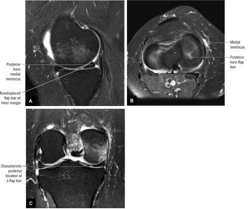 FIGURE 4.106 ● Coapted or nondisplaced flap tears of the posterior horn medial meniscus. (A) Inner margin vertical grade 3 signal intensity is identified in the sagittal plane. (B) Direct visualization of flap morphology is demonstrated on this axial image. (C) The common location of a flap tear identified on this posterior coronal image. In comparison, a classic (non-root) radial tear would be visualized on a more peripheral sagittal image (at the anterior or posterior horn-body junction) and on a coronal image more anterior to the plane of the posterior horn, usually where the condyles fuse. |
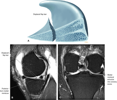 FIGURE 4.107 ● (A) Color sagittal illustration of the superior view of a displaced non-coapted flap tear of the posterior horn of the medial meniscus. (B) FS PD FSE sagittal image with inner-third vertical tear grade 3 signal intensity. (C) FS PD FSE coronal image showing extrusion of the meniscus with fragment displacement into the coronary recess. |
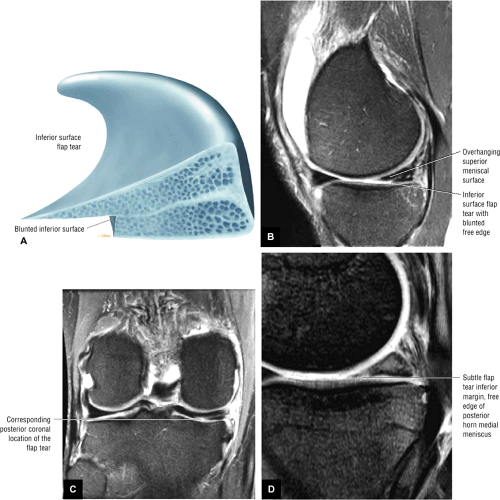 FIGURE 4.108 ● (A) Illustration of inferior surface flap tear subtype. (B) Corresponding sagittal FS PD FSE image. (C) Foreshortened and blunted inferior leaf is illustrated on a corresponding posterior coronal image. The flap tear pattern is specific on sagittal images, and the posterior coronal image location is confirmatory. (D) Additional flap tear variant limited to the free edge of the meniscus. Although this morphology may be mistaken for meniscal fraying, there is a relative deficiency of the inferior leaf resulting in a small flap tear of the inner margin of the posterior horn. |
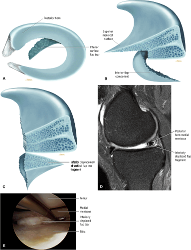 FIGURE 4.109 ● (A) Axial view of a medial meniscus inferior surface flap tear. (B, C) Inferior displaced flap tear producing a blunted posterior horn of the medial meniscus. The stacked meniscal leaflets create a “double-decker” pattern. Rotation of the flap tear fragment may be from the inferior leaf (B) or the entire inner third of the meniscus (C). (D) Sagittal FS PD FSE image. (E) Arthroscopic view of blunted appearance of medial meniscus resulting from displacement of an inferior flap tear. |
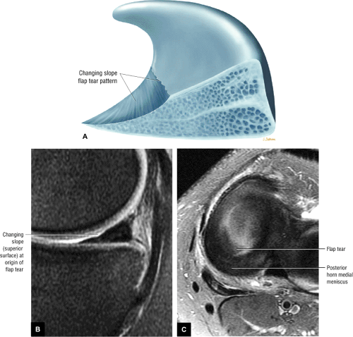 FIGURE 4.110 ● Changing slope sign (A) of a flap tear with correlative sagittal image (B). (C) Free edge flap component is seen on this corresponding axial image. |
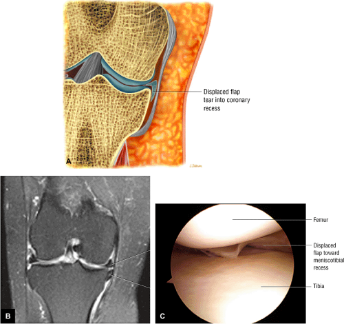 FIGURE 4.111 ● Separation of displaced medial meniscus flap fragment with inferior displacement into coronary recess on (A) color coronal section and (B) coronal FS PD FSE image. (C) Arthroscopic view of a hidden flap tear showing a rolled appearance in the posterior horn as the flap fragment displaces into the meniscotibial recess. |
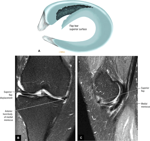 FIGURE 4.112 ● Superior flap rotation (A) producing the “double-decker” morphology of the medial meniscus in the coronal plane (B). Anterior displacement of the superior flap is best identified on the corresponding FS PD FSE sagittal image (C). |
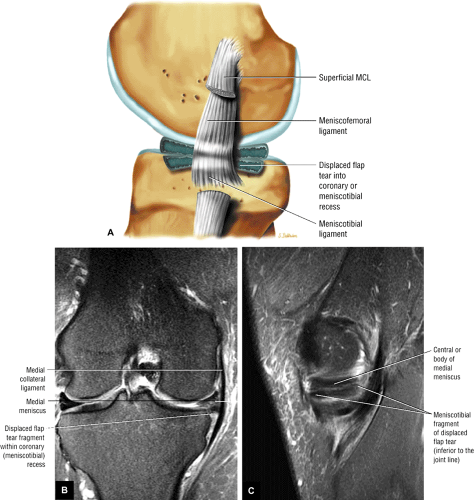 FIGURE 4.113 ● Displaced flap tear into coronary recess on sagittal (lateral) color illustration (A), FS PD FSE coronal image (B), and sagittal image (C). |
A flap tear is the most commonly seen tear pattern and frequently develops after minimal meniscal trauma superimposed on a degenerative process resulting from chronic shear forces. Acute tears may occur after sudden impact on the meniscus, usually with a twisting component. Degenerative flap tears most commonly involve the inferior leaf, but relative deficiency of the inner margin of the superior surface of the meniscus may also result in a flap tear. In addition, flap tear leaflets may displace either anteriorly (Fig. 4.116) or posteriorly (Fig. 4.117). A complex meniscal tear may demonstrate both flap and radial components, especially in the medial meniscus (Fig. 4.118). Since flap tears are often extensions of radial tears or horizontal cleavage tears, both tear patterns may coexist in the same meniscus and even in the same meniscal sagittal section or image. In fact, the separate features of flap, radial, and longitudinal tears should be described when part of a complex flap tear (Fig. 4.119).
Since flap tears represent a change in the direction of meniscal signal, flap tear morphology can be inferred when grade 3 signal intensity extends to the superior and inferior surfaces of the meniscus on separate sagittal images in different locations. As mentioned, rotation of a meniscal flap tear or complex folding of a meniscal flap may result in stacking of the flap on the residual meniscus, producing a double-decker morphology or a double layer of meniscal tissue, usually seen in the peripheral one third to one half of the meniscus on sagittal images. Flap tears may also generate an anterior- or posterior-based flap of meniscus.42 The popliteus tendon sheath may serve as a potential space for a displaced lateral meniscus flap tear (Fig. 4.120). Reactive plateau edema is frequently associated with displaced flap tears (Fig. 4.121). It is seen more commonly in the medial compartment and is associated with increased load transference to the chondral surface and subchondral bone. This load transference is increased in the presence of meniscal dysfunction. Unlike bucket-handle tears, flap tears do not demonstrate complete posterior-to-anterior extension and displacement of the involved meniscal fragment (Fig. 4.122). Unlike classic (non-root) radial tears, flap tears commonly involve the posterior horn of the meniscus, whereas classic radial tears usually demonstrate normal meniscal morphology on posterior coronal images (Fig. 4.123).
Impingement of the mobile flap fragment results in traction on the innervated peripheral meniscal rim, causing clinical symptoms. Flap tears that involve the avascular inner edge of the meniscus are irreparable.77 Treatment is partial meniscectomy with transection through the base and contouring of the remaining attachment to a stable rim.87 Residual peripheral horizontal grade 3 signal intensity is often seen after arthroscopic resection of the flap.
MR Accuracy
Compared with arthroscopy, the sensitivity of MR imaging of meniscal tears has been reported to be between 80% and 100%.6,25,27,53,66,88,89,90,91,92,93,94,95,96,97,98 In a series by Mink et al., 600 menisci were studied with an overall accuracy rate of 92%; there were 9 false-negative and 18 false-positive findings.99 With fast 3D MR imaging, there is a 95% concurrence between MR imaging and arthroscopy in the detection of meniscal tears and a 100% correlation for meniscal degeneration.100 Li et al. studied 459 menisci and reported an arthroscopic correlation of 93%.19 The negative predictive value of MR imaging approaches 100%, and correlation of peripheral meniscal signal intensity on sagittal MR images with coronal plane images of the corresponding menisci may reduce the incidence of false-positive MR findings, especially in the posterior horn of the medial meniscus.
MR is particularly useful in cases of multiple or complex knee lesions, in which the accuracy of the clinical knee examination drops from 72% for a single lesion to 30%.101 The possibility of an associated meniscal tear in the presence of a clinically deficient ACL knee or an existing MCL tear is a clinical indication for MR referral. The improved sensitivity of MR in the detection of chondral lesions using FS FSE techniques may further improve clinical diagnostic accuracy for treatment and patient care.
La Prade et al. found meniscal tears in 5.6% of asymptomatic patients.66 Lateral meniscal tears were twice as common as medial meniscal tears. In addition, grade 2 signal intensity involving the posterior horn of the medial meniscus was found in 24.1% of cases. MR findings of grade 2 signal intensity in the posterior horn of the medial meniscus correlate with histologic studies showing that the posterior horn of the medial meniscus receives the greatest femoral tibial forces during biomechanical loading and is the most frequent site of grade 2 signal intensity. Nonetheless, depiction of grade 2 signal intensity in asymptomatic patients cannot be used to prospectively predict progression to fibrocartilaginous weakening, which may eventually result in a meniscal tear. Although this study reported accuracy rates of 98.6% for the medial meniscus and 90.3% for the lateral meniscus as correlated with arthroscopy, it is essential that clinical examination findings be coordinated with MR studies, based on the 5.6% prevalence of meniscal tears in asymptomatic persons.
Variations in the accuracy rates of MR compared with those of arthroscopy may be due to the following factors:
Differences in the learning curves of radiologists in interpreting MR signal intensities
Differences in the experience of several arthroscopists participating in the correlative studies
False interpretation of areas of fibrillation or fraying as meniscal tears
Inability of arthroscopy to detect intrasubstance degenerative cleavage tears
Obstructed arthroscopic visualization of the posterior horn of the medial meniscus by the medial femoral condyle
Difficulty in accurately imaging the periphery of the meniscus at the meniscocapsular junction
Variability in examinations using different MR imaging equipment and surface coils at a variety of field strengths
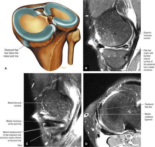 FIGURE 4.114 ● (A) Displaced flap tear with fragment rotation into the meniscotibial or coronary recess and characteristic deficient inner margin or inferior leaf on color illustration. (B) The superior medial perspective is shown on this sagittal image. Meniscal extrusion with inferior displacement of the flap can be seen on corresponding sagittal (C) and axial (D) images. |
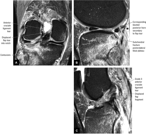 FIGURE 4.115 ● Displaced flap tear associated with ACL disruption. The posterior horn fragment is displaced into the posterior intercondylar notch posterior to the ACL. ACL-associated flap tears result from combined radial and longitudinal tear components. There is extension of the tear adjacent to the lateral meniscus root. (A) Coronal FS PD FSE image. (B, C) Sagittal FS PD FSE images. |
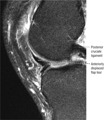 FIGURE 4.116 ● Flap tear variant with vertical superior folding of the anterior fragment (sagittal FS PD FSE image). |
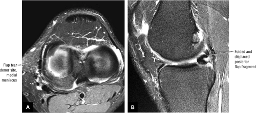 FIGURE 4.117 ● Flap tear variant involving the body and posterior horn producing vertical superior folding of the rotated flap fragments (the reverse S sign of a complex flap tear). (A) Axial FS PD FSE image. (B) Sagittal FS PD FSE image. |
Discoid Meniscus
Pearls and Pitfalls
Discoid Meniscus
Incomplete discoid menisci can be differentiated from complete discoid types by the degree of discoid morphology. No anterior or posterior horn equivalents are identified in the complete discoid meniscus (type A).
Prominent or cavitary grade 2 signal intensity in a discoid meniscus may be associated with positive clinical signs and symptoms related to the lateral compartment.
The popping or snapping knee syndrome is associated with the Wrisberg variant (absence of the posterior coronary ligament).
A discoid meniscus is a dysplastic meniscus that has lost its normal or semilunar shape and has a broad disc-like configuration. 102,103,104 Lateral discoid menisci are more common than medial discoid menisci, and the degree of enlargement varies from mild hypertrophy to a bulky slab of fibrocartilage (Fig. 4.124). The incidence of discoid menisci is reported to be 1.4% to 15.5%.105 The rare medial discoid meniscus is found in 0.3% of meniscectomies (Fig. 4.125).26 Watanabe’s classification groups discoid menisci into incomplete (Fig. 4.126), complete
(Fig. 4.127), and Wrisberg-ligament type (Wrisberg variant) (Fig. 4.128). Complete and incomplete refer to the degree or extent to which the meniscus demonstrates discoid morphology with an intact posterolateral meniscotibial ligament.26,106 In the Wrisberg-ligament type, meniscal morphology is normal and the deformity is defined either by the absence of the posterior capsular attachment (the posterior meniscotibial coronary ligament) or by the coverage area of the lateral tibial plateau. The deficiency or lack of posterior capsular attachment is thought to result in incomplete mediolateral motion, trauma, and secondary hypertrophy of the hypermobile meniscus.107 There is no medial meniscus counterpart to the Wrisberg-ligament type discoid lateral meniscus.
(Fig. 4.127), and Wrisberg-ligament type (Wrisberg variant) (Fig. 4.128). Complete and incomplete refer to the degree or extent to which the meniscus demonstrates discoid morphology with an intact posterolateral meniscotibial ligament.26,106 In the Wrisberg-ligament type, meniscal morphology is normal and the deformity is defined either by the absence of the posterior capsular attachment (the posterior meniscotibial coronary ligament) or by the coverage area of the lateral tibial plateau. The deficiency or lack of posterior capsular attachment is thought to result in incomplete mediolateral motion, trauma, and secondary hypertrophy of the hypermobile meniscus.107 There is no medial meniscus counterpart to the Wrisberg-ligament type discoid lateral meniscus.
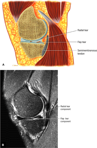 FIGURE 4.118 ● Continuity of a radial tear and flap tear pattern in the medial meniscus. The tear initiates as a radial tear, then changes direction with a longitudinal component to create the flap pattern. The relative deficiency of the inner margin of the inferior leaf with blunting of the remaining inferior leaf is characteristic of a flap tear. (A) Sagittal color illustration. (B) FS PD FSE sagittal image. |
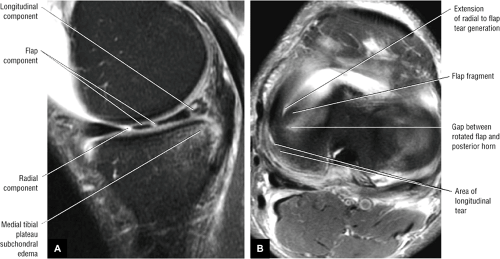 FIGURE 4.119 ● (A) FS PD FSE sagittal image illustrating a complex tear with radial tear, longitudinal tear, and flap tear components. (B) Corresponding FS PD FSE axial image identifies both the flap and radial components. |
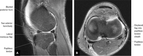 FIGURE 4.120 ● Displaced lateral meniscus flap tear in the popliteus tendon sheath. Tear can be seen inferior to the lateral joint line and anterior to the popliteus tendon. (A) Sagittal FS PD FSE image. (B) Axial FS PD FSE image. |
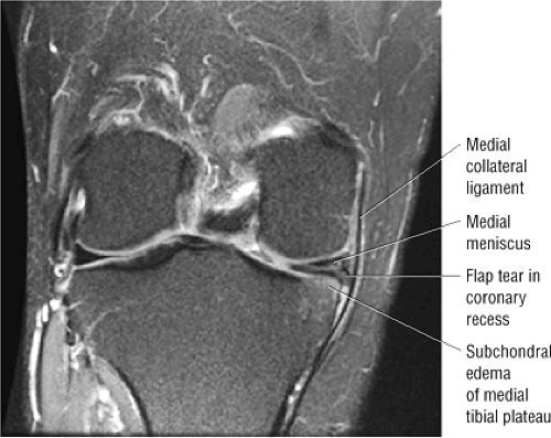 FIGURE 4.121 ● Medial tibial plateau marrow edema associated with medial meniscus flap tear. Compressive loading of the medial compartment associated with meniscal dysfunction leads to increased load transference to both the articular cartilage and subchondral bone. |
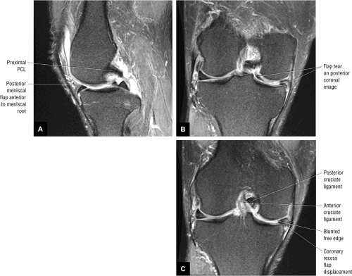 FIGURE 4.122 ● Flap tear mimicking a bucket-handle tear. (A) Posterior double delta sign on sagittal image. (B) Corresponding posterior coronal image showing intercondylar notch displacement. (C) Anterior coronal images, however, do not show anterior extension of the displaced meniscal flap fragment. Diagnosis of a true bucket-handle tear requires identification of displaced meniscal tissue on both posterior and anterior coronal images. |
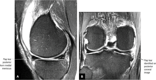 FIGURE 4.123 ● Posterior horn medial meniscus flap tear on sagittal image (A) triangulates to abnormal meniscal signal intensity on a corresponding posterior coronal image (B). |
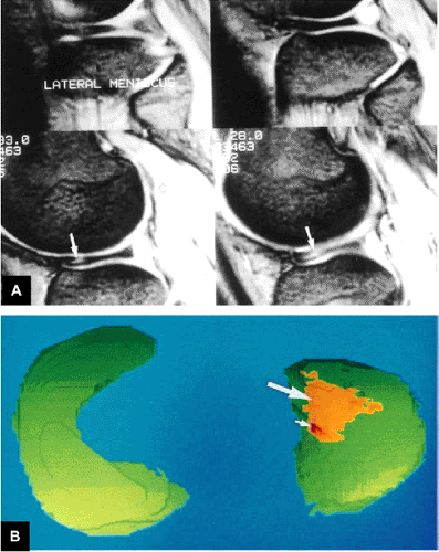 FIGURE 4.124 ● (A) A lateral discoid meniscus. The fibrocartilage of the separate anterior and posterior horns has a slab-like morphology as seen on consecutive T2*-weighted sagittal images. A superior surface tear (arrow) is demonstrated with associated intrasubstance degeneration. (B) A 3D MR rendering shows intrasubstance degeneration (orange and large arrow) and a superior surface tear (red and small arrow). |
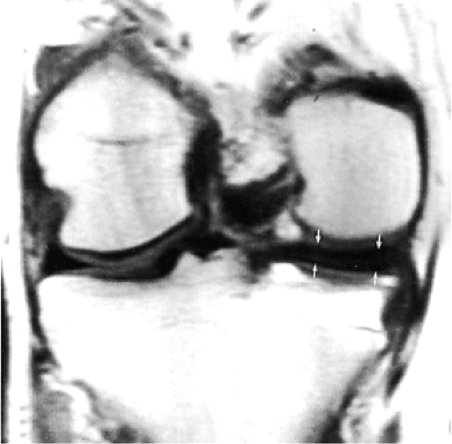 FIGURE 4.125 ● Dysplastic hypertrophied band of medial meniscus fibrocartilage on coronal image through a medial discoid meniscus. |
Discoid menisci are considered congenital deformities and are frequently bilateral. They present as fibrocartilaginous masses with an oval or circular shape. The thickness of the fibrocartilage varies from 5 to 13 mm.105 A complete discoid meniscus extends to the intercondylar notch (Fig. 4.129). An anterior megahorn discoid meniscus occurs when the posterior horn is normal but the anterior horn and body form a solid mass of fibrocartilage. Discoid menisci are susceptible to tears and cysts, and young patients often present with symptoms of torn cartilage. Pain, clicking or snapping, and locking are common presenting clinical findings in children.42,108 Clinical symptoms of a discoid lateral meniscus may not develop until adolescence. The Wrisberg-ligament type of discoid meniscus may, however, present earlier with lateral joint pain with or without an audible or palpable “clunk.” McMurray’s test may be negative on clinical examination, and in fact most discoid menisci are asymptomatic.
The differential diagnosis of a discoid meniscus includes any condition that presents as a “snapping knee” on physical examination (a snapping sound during knee flexion and extension). The following conditions are included in the differential:
Patellofemoral joint subluxation or dislocation
Meniscal cysts
Congenital subluxation of the tibiofemoral joint
Subluxation or dislocation, or both, of the proximal tibiofibular joint
Snapping of the tendons about the knee on an osteophyte or roughened surface
A displaced flap tear or bucket-handle tear
Treatment of the unstable inner segment of a discoid meniscus requires cauterization or resection (partial meniscectomy) to a stable rim. The Wrisberg-ligament type of discoid lateral meniscus is prone to medial displacement into the intercondylar notch and is best treated with a total meniscectomy.43,109 Some patients with symptomatic discoid menisci have undergone cauterization and partial resection in the presence of intrasubstance degeneration without a surface tear.106 On MR examination these menisci demonstrate prominent or thick horizontal grade 2 signal intensity oriented along the middle collagen bundle or shear plane of the meniscus. Except for cases of discoid lesions, menisci with grade 2 signal intensity are not usually treated at arthroscopy.106,110
Imaging findings in the evaluation of discoid menisci include the following:
Plain-film radiographs (although usually of limited value) may show widening (Fig. 4.130) of the involved compartment (lateral joint space), a hypoplastic lateral femoral condyle, a high fibular head, chondromalacia, cupping of the lateral tibial plateau, and a squared-off lateral femoral condyle.111
Arthrography demonstrates an elongated and enlarged meniscus that extends toward the intercondylar notch.
On sagittal MR images, using a 4-mm slice thickness, a discoid meniscus exhibits a continuous or bowtie appearance on three or more consecutive images.108,111 Demon-stration of the anterior and posterior horns is limited to one or two sagittal sections adjacent to the intercondylar notch. Central tapering, seen in the normal meniscus on sagittal images, is lost in discoid fibrocartilage.
The increased inferior-to-superior dimensions of the meniscus can be appreciated on both coronal and sagittal images. A discoid meniscus may be as much as 2 mm higher than the opposite meniscus.112
Coronal images show the extension of the discoid meniscus apex toward or into the intercondylar notch.
In a complete discoid meniscus, meniscal fibrocartilage without distinct anterior and posterior horns is usually interposed between the femoral condyle and the tibial plateau on every sagittal image through the involved compartment.
In the more common incomplete discoid type of meniscus, the meniscus does not extend into the intercondylar notch on coronal images.
If the radial diameter, as shown on coronal images through the body or central third of the meniscus, measures 13 mm from the capsular margin to the free edge, a discoid meniscus is probable.26 Normally, the central coronal image displays the smallest radial cross-section of the meniscal body, thus making this image sensitive to the enlargement seen in discoid menisci.
In the presence of an effusion, the enlarged meniscus is outlined with high-signal-intensity fluid on FS PD FSE, T2*-, or STIR-weighted images.
Axial images demonstrate the circumferential morphology of both incomplete and complete discoid menisci. Grade 2 signal intensity and discoid menisci may correlate with intrameniscal cavitations or cysts, and many orthopaedic surgeons recommend meniscectomy for a symptomatic discoid meniscus, even without grade 3 signal intensity. These menisci usually demonstrate a prominent and thickened grade 2 signal intensity that may correlate with an intrasubstance cleavage tear.
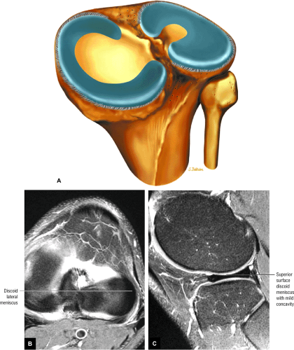 FIGURE 4.126 ● Incomplete discoid lateral meniscus illustrated on superior view (A) and shown on corresponding axial (B) and sagittal (C) FS PD FSE images. Note there is slight surface concavity in the body of the partial discoid fibrocartilage on the sagittal image (C). |
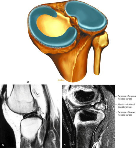 FIGURE 4.127 ● (A) Color illustration of superior view of a complete discoid lateral meniscus from a posterior perspective. (B) The thick slab of lateral meniscal fibrocartilage is seen as a continuous low-signal-intensity band on corresponding sagittal image (arrows). The superior surface of the complete discoid meniscus has no concavity. (C) Symptomatic discoid lateral meniscus in 3-year-old with mucoid expansion of the posterior aspect of the lateral meniscus. |
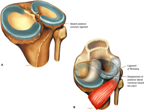 FIGURE 4.128 ● (A) Wrisberg variant with absence of the posterior coronary ligament on posterior superior view. (B) Without meniscotibial restraint, there is potential for entrapment of the posterior aspect of the fibrocartilage. In extension the attached Wrisberg ligament pulls and displaces the posterior aspect of the meniscus into the intercondylar notch. |
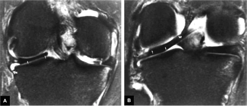 FIGURE 4.129 ● A complete discoid meniscus (small arrows) interposed between the lateral femoral condyle and tibial plateau extending to the intercondylar notch on FS PD-weighted FSE coronal images. An intact meniscotibial ligament (A, curved arrow) and Wrisberg-ligament (B, W) are shown. |
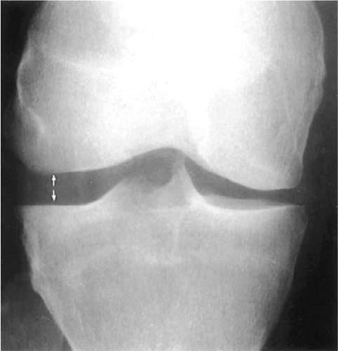 FIGURE 4.130 ● Convention radiographs show lateral joint space widening in complete discoid menisci. |
Pitfalls in Interpretation of Meniscal Tear Findings
Pearls and Pitfalls
Meniscal Tears
Attenuation of grade 3 signal intensity extension to an articular surface is associated with a closed meniscal tear.
External rotation of the knee may accentuate the course of the meniscofemoral ligaments. The ligament of Wrisberg is often mistaken for a peripheral tear of the posterior horn of the lateral meniscus.
Meniscal flounce does not indicate the existence of or increased association with a meniscal tear.
Knowledge of the more common pitfalls encountered in MR imaging of the meniscus helps to maintain high specificity and accuracy of diagnostic interpretations of meniscal tears.26,94,113,114,115,116
Grade 2 vs. Grade 3 Signal Intensity
In some cases (<5% in our experience), it is difficult to distinguish articular surface extension of signal intensity. In such cases, evaluation of the morphology of the meniscus as well as the degree and thickness of increased signal intensity may facilitate a more accurate interpretation. Weakening or decreased signal intensity of a grade 3 lesion as it approaches an articular surface, for example, favors a diagnosis of an intrasubstance closed tear that, at arthroscopy, might require surgical probing for detection. In the presence of a joint effusion, grade 3 signal, which becomes more conspicuous with conventional T2 weighting, corresponds to a disrupted meniscal surface, which facilitates the influx of free water molecules (i.e., T2 prolongation).
Correlation with corresponding coronal images may be helpful in patients with peripheral signal intensity or when grade 2 and grade 3 signal intensities cannot be differentiated. By providing a plane perpendicular to that seen on orthogonal sagittal images, extension to the superior or inferior surface of the meniscus or meniscal apex can be more easily determined.92
Artifact
Peripheral signal artifact (also called annefact or star artifact) can appear as either a bright spot or as a ribbon of bright signal smeared through the image. It occurs when signals are generated outside the field of view (FOV) and the receiver coil is able to detect them. The artifact is generally seen when a body coil is used to transmit radiofrequency and a phased-array coil is used to receive the signal. On long-axis images, sagittal or coronal, the artifact typically occurs if the phase encoding is selected along the superior-to-inferior (SI) direction and the receiver coils extend beyond the imaging FOV. The bright signal originates outside the FOV and is aliased back into the image. This can also happen with transmit-receive coils if tissue outside the FOV is excited. The artifact may overlap the meniscus in the sagittal plane when using FSE sequences (Fig. 4.131).
The following steps may be taken to reduce the likelihood of producing artifact:
Use S-I frequency when possible.
Ensure that the imaging FOV matches the receiver coil coverage, or use a smaller RF coil with reduced S-I coverage when possible. If using a CTL coil, select only that needed for the FOV.
Offset the FOV along the S-I or L-R direction to change the position of the artifact. Although this does eliminate the artifact, it is sometimes the best way to achieve useable images without changing phase and frequency
coils. Only a few centimeters of offset may be sufficient to shift the artifact so that it no longer overlaps the critical area of the meniscus at the level of the joint line.
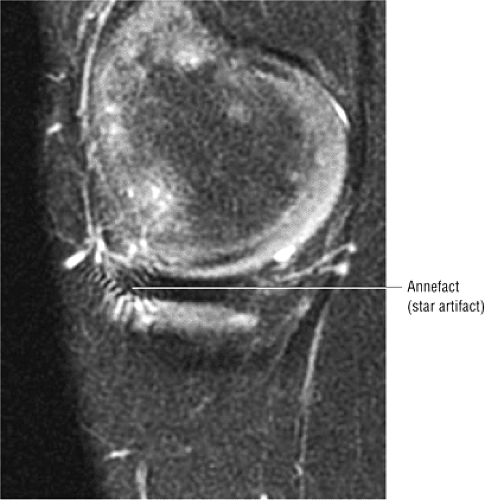 FIGURE 4.131 ● Annefact artifact obscuring the anterior aspect of the body of the medial meniscus at the level of the joint line on a FS PD FSE sagittal image. |
A less common pitfall involves a truncation artifact, which may mimic a meniscal tear when a 128 × 128 matrix with a 128-pixel phase-encoded axis is oriented in the S-I direction.117 This type of artifact is minimized when a 192 or 256 × 256 matrix is used. A pseudo-tear may be seen when the high-signal-intensity artifact is projected over the low-signal-intensity meniscus.118 This artifact is most conspicuous 2 pixels from the high-contrast interface between the meniscus and the articular cartilage.
Transverse Ligament
The transverse ligament of the knee, which connects the anterior horns of the medial and lateral meniscus, can simulate an oblique tear adjacent to the anterior horn of the lateral meniscus (Fig. 4.132). The transverse ligament originates anterolateral to the central rhomboid attachment of the lateral meniscus. The central rhomboid attachment of the anterior horn of the lateral meniscus may normally demonstrate linear increased signal intensity. On sagittal or axial images, the transverse ligament can be identified coursing between the tibial attachment of the ACL and Hoffa’s infrapatellar fat pad to its insertion on the anterior superior aspect of the anterior horn of the medial meniscus. In the presence of a joint effusion, increased signal intensity may be present in the interface between the transverse ligament and the anterior horn of the lateral meniscus on FS PD FSE images.
The transverse ligament varies in diameter and is absent in 40% of gross specimens. In up to 30% of MR examinations, the fat that surrounds the low-signal-intensity ligament mimics grade 3 signal intensity. In 15% of MR examinations, the transverse ligament can be followed in its entire medial-to-lateral extent.118 Infrequently the medial extent of the transverse ligament may simulate a tear adjacent to the anterior horn of the medial meniscus. Axial images demonstrate the course of the transverse ligament as a low-signal-intensity band traversing Hoffa’s infrapatellar fat pad. On serial sagittal images, the round transverse ligament may be traced from the anterior horn of the lateral meniscus to the anterior horn of the medial meniscus. The central attachment of the anterior horn of the medial meniscus is located anterior to the transverse ligament when viewed in the sagittal plane (see Fig. 4.132). The transverse ligament, however, is always identified anterior to the anterior horn of the lateral meniscus. As a function of external rotation of the knee, the transverse ligament may assume a more linear morphology in the attachment to the anterior horn of the lateral meniscus (Fig. 4.133).
Anterior Horn of the Lateral Meniscus
Isolated tears of the anterior horn of the lateral meniscus can be easily differentiated from transverse ligament pseudo-tears and are relatively uncommon compared to other meniscal tear locations. The central anterior ligamentous attachment of the anterior horn of the lateral meniscus itself may be mistaken for a meniscal tear. This attachment, which is rhomboid, is normally directed obliquely upward on sagittal images and frequently contains increased internal signal intensity (Fig. 4.134). In this location the increased signal intensity is sometimes referred to as “speckled.” It may be visualized on one or two sagittal images adjacent to the intercondylar notch and occurs near the origin of the transverse ligament. Excessive external rotation of the knee results in pseudo-foreshortening of the anterior horn of the lateral meniscus relative to the posterior horn and is associated with apparent anterior to posterior elongation of the femoral condyle.
Fibrillation
Fibrillation or fraying of the concave free edge of the meniscus facing the intercondylar notch is seen as increased signal intensity restricted to the apex of the meniscus in the presence of normal meniscal morphology (Fig. 4.135). If, however, there is abnormal morphology (truncation or foreshortening of the meniscus), a meniscal tear (radial or flap tear) is likely. FS PD-weighted FSE images are useful in defining the meniscal outline or morphology but are less sensitive to the detection of intrameniscal signal intensity. It is sometimes difficult to differentiate between the MR characteristics of fraying and tearing of the meniscus.93 A macerated meniscus imbibes synovial fluid throughout its substance and demonstrates a diffuse increase in signal intensity (multiple grade 3 tears). Posttraumatic diffuse increased intrameniscal signal intensity without a discrete meniscal tear may be seen in a more acute setting (Fig. 4.136). This finding has been loosely referred to as meniscal contusion or posttraumatic meniscal edema.119 This amorphous meniscal signal should not be confused with the meniscocapsular or meniscal corner fractures that occur with ACL tears and in fact represent true meniscal tearing.
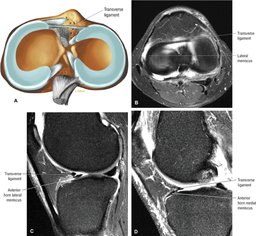 FIGURE 4.132 ● The transverse ligament of the knee connects the anterior horns of the medial and lateral menisci. (A) Axial superior view color illustration showing the transverse ligament coursing anterior to the anterior horn of the lateral meniscus. In the medial compartment anterior horn fibrocartilage extends anterior to the transverse ligament attachment. Axial (B) and sagittal (C, D) FS PD FSE images. The transverse ligament (B) is located anterior to the anterior horn of the lateral meniscus (C) and posterior to the anterior horn of the medial meniscus (D). The anterior horn of the medial meniscus extends anterior to the more superiorly located transverse ligament. The transverse ligament is also located directly posterior to the free edge of Hoffa’s fat pad. |
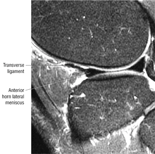 FIGURE 4.133 ● Sagittal FS PD FSE image shows a linear morphology of the transverse ligament. |
Popliteus Tendon
In the posterior horn of the lateral meniscus, the popliteus tendon sheath may be mistaken for grade 3 signal intensity and can be falsely interpreted as a tear (Fig. 4.137). The popliteus tendon sheath is intermediate in signal intensity on T1- and FS PD- or T2-weighted images and courses in an oblique, anterosuperior-to-posteroinferior direction, anterior to the low-signal-intensity popliteus tendon. In the presence of a joint effusion, fluid in the popliteus sheath demonstrates bright signal intensity on T2- or T2*-weighted images. In addition, the superior and inferior fascicles of the posterior horn of the lateral meniscus are best displayed on T2-weighted images (including FS PD-weighted FSE or T2*-weighted sequences) in the presence of a joint effusion. A fascicle tear should not be confused with the normal superior and inferior meniscocapsular defects, which allow passage of the popliteus tendon through the popliteus hiatus (Figs. 4.138 and 4.139). In the sagittal plane, the most lateral image through the popliteus tendon displays the anatomy of the inferior fascicle, with normal deficiency of the superior fascicle (Fig. 4.140). More medially, both the superior and inferior fascicles are visualized. The most medial image through the popliteus tendon and sheath displays the superior fascicle with normal deficiency of the inferior fascicle. The course of the popliteus muscle and tendon can be followed on serial axial, sagittal, and posterior coronal images. The thickness of the popliteus tendon sheath is variable and may be identified as a thin line or a thick band. A true peripheral lateral meniscal tear usually presents with a different obliquity than that described for the popliteus tendon sheath (Fig. 4.141). A vertical tear of the posterior horn of the lateral meniscus, however, may parallel the popliteus tendon sheath. In such cases, the popliteus tendon should be used as a landmark for the location of the peripheral edge of the meniscus. After lateral meniscectomy, the low-signal-intensity popliteus tendon may be mistaken for a retained posterior horn remnant. Continuity with the popliteus tendon helps to avoid this misdiagnosis.
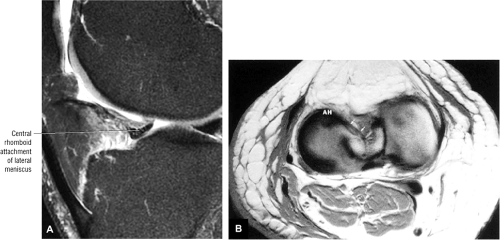 FIGURE 4.134 ● (A) Sagittal FS PD FSE image shows the speckled pattern of the normal central rhomboid attachment of the anterior horn of the lateral meniscus. (B) T1-weighted axial image of the central rhomboid attachment (small arrows) of the anterior horn (AH) of the lateral meniscus. |
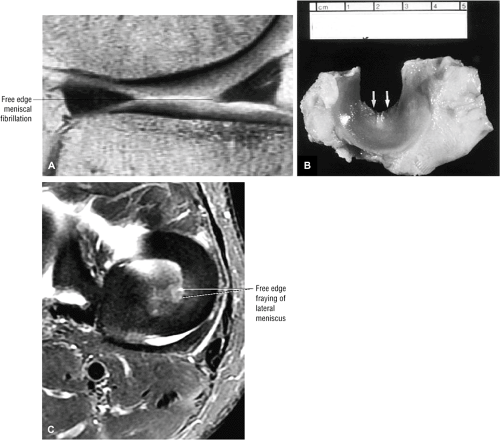 FIGURE 4.135 ● (A) Minimal blunting and intermediate signal intensity restricted to the apex of the meniscus representing degenerative fibrillation or fraying. These changes may be mistaken for a radial tear. (B) Gross specimen shows a meniscus with fibrillation along the concave free edge (arrows). (C) Free edge lateral meniscal fraying without defined meniscal tear. |
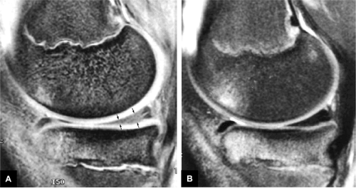 FIGURE 4.136 ● (A) Acute posttraumatic diffuse “meniscal edema” (arrows) is hyperintense on this T2*-weighted sagittal image. (B) On a corresponding FS PD-weighted FSE sagittal image, however, the posterior horn of the medial meniscus demonstrates normal morphology without tearing. Associated anterior medial compartment bone contusions can be seen on this sequence. |
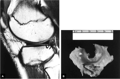 FIGURE 4.137 ● Popliteus tendon and sheath. (A) T1-weighted sagittal image demonstrating the intermediate-signal-intensity popliteus tendon sheath (curved arrow) and the low-signal-intensity popliteus tendon (straight arrow). (B) The corresponding gross specimen shows the course of the popliteus tendon (arrow) along the posterior horn of the lateral meniscus. |
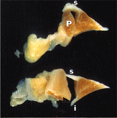 FIGURE 4.138 ● Examination of a gross anatomic specimen allows identification of the superior (s) and inferior (i) fascicles. The popliteus tendon (P) passes normally through defects in the inferior and superior fascicles. |
Partial Volume Averaging
The concave peripheral meniscal edge may produce the appearance of grade 2 signal intensity on peripheral sagittal images through the body of the meniscus.113 This appearance is more commonly seen in the medial meniscus and is caused by partial volume averaging of fat and neurovascular structures lying in the concavity of the meniscus. This artifact has been reported in up to 29% of medial and 6% of lateral menisci.118 Corresponding thin-section radial or coronal images, however, display an intact meniscal structure and may display the concave margin of the meniscus.
Meniscofemoral Ligaments
Laterally, the meniscofemoral ligament consists of the ligament of Humphrey, which extends anterior to the PCL, and a posterior branch of the ligament of Wrisberg, seen posterior to the PCL (Fig. 4.142). The meniscofemoral ligament most commonly has direct attachment to the lateral meniscus and is obliquely oriented to its insertion on the medial femoral condyle. The posterior branch of the meniscofemoral ligament, the ligament of Wrisberg, is the larger of the two branches and may appear to be half the cross-sectional diameter of the PCL.118 The anterior meniscofemoral ligament has been reported to be present in 34% of anatomic dissections and the posterior meniscofemoral ligament in 60%. MR visualization has been reported in 33% of cases for either ligament, and in 3% of MR examinations both structures are identified. One branch of the meniscofemoral ligament usually predominates. The ligament of Humphrey can be best seen on sagittal images, whereas the ligament of Wrisberg is best shown on posterior coronal images. The ligament of Humphrey can, however, be identified on coronal images (Fig. 4.143).
Meniscal insertion of the meniscofemoral ligament may mimic the appearance of a vertical tear in the posterior horn of the lateral meniscus (Fig. 4.144).120 This pseudo-tear, the result of fat and or fluid interposed between the meniscus attachment and the meniscofemoral ligament, can be seen extending obliquely from the superior meniscal surface and is directed posteriorly and inferiorly toward the inferior meniscal surface. With external rotation of the knee, the interface between the meniscofemoral ligament and the posterior horn of the lateral meniscus becomes more prominent. In this location the ligament of Wrisberg is more likely than the ligament of Humphrey to be mistaken for meniscal pathology.
Oblique meniscomeniscal ligaments, which pass between the anterior and posterior cruciate ligaments, also may be mistaken for a displaced flap tear or bucket-handle tear (Fig. 4.145).121 The oblique meniscomeniscal ligament passes from the anterior horn of one meniscus to the posterior horn of the opposite meniscus.
Pseudo–Bucket-Handle Tear
On posterior coronal images that traverse both the body and the posterior horn of the lateral meniscus, separate portions of the posterior horn may be mistaken for a lateral bucket-handle tear. This is more likely to occur with the knee positioned in external rotation (Fig. 4.146). This appearance is not usually encountered on posterior coronal images through the medial meniscus. Correlation with sagittal images shows normal meniscal morphology without tearing.
Pseudohypertrophy of the Anterior Horn (Anterior Flipped Meniscus)
Complex meniscal tears may present with a unique MR appearance. In the lateral meniscus, the posterior horn may be absent or truncated, or it may be displaced or flipped anteriorly, occupying the space adjacent to the anterior horn (Fig. 4.147), creating pseudohypertrophy of the anterior horn fibrocartilage. This pattern is commonly seen in bucket-handle tears of the lateral meniscus.82 The two meniscal horns are separated by an interface of fluid. The flipped posterior horn tissue is posterior to the anterior horn.
Lax Meniscal Sign or Meniscal Flounce
Sometimes a lax or redundant folding, buckling, or flounce in the meniscus contour is present without any associated fibrocartilage tear (Fig. 4.148). This finding is seen more commonly in the medial meniscus and is best visualized when there is an associated effusion and/or joint laxity. A flounce contour without associated meniscal pathology may also be seen in the lateral meniscus (Fig. 4.149). The lax or “buckled meniscus” sometimes simulates a central or peripheral meniscal tear. However, this phenomenon may disappear with joint manipulation or subsequent imaging. A true meniscal flounce or fold represents a normal variant, provided there are no other associated indicators of meniscal pathology. The presence of a meniscal flounce is not associated with an increased prevalence of meniscal tears.
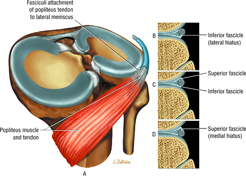 FIGURE 4.139 ● The popliteus tendon is extra-articular but intracapsular and susceptible in posterolateral corner injuries. It is covered by a synovial membrane on its medial aspect. The popliteal hiatus is bound anteroinferiorly by the superior fascicle. These fascicles are also referred to as popliteomeniscal ligaments. Normal deficiencies of the fascicle allow passage of the popliteus tendon from the lateral (B) to the medial (D) aspect of the hiatus. Both superior and inferior fascicles are shown at the midportion of the hiatus (C). |
Vacuum Phenomenon
The magnetic susceptibility of normal amounts of intra-articular gas may produce a low-signal-intensity void or blooming artifact on GRE images (Fig. 4.150). This artifact may be mistaken for a meniscal tear or articular cartilage injury.
Pseudo–Loose Body
Normal high-intensity fat intercondylar notch signal may be mistaken for a loose body on T2*-weighted or FS coronal or sagittal images. This is unlikely to occur if T1-weighted images are correlated with corresponding GRE or FS images.
MCL Bursa
The bursa of the MCL is seen between the periphery of the body of the medial meniscus and the MCL.8 On T2-weighted images, fluid within the bursa may be falsely mistaken for a peripheral meniscocapsular tear.
Magic-Angle Phenomenon
On short-TE images, the magic-angle phenomenon may be responsible for increased signal intensity in the upward-sloping portion, or medial segment, of the posterior horn of the normal lateral meniscus.116 This effect, a function of the anisotropic behavior of normal meniscal fibrocartilage, is seen in meniscal sections oriented at approximately 55° relative to the static magnetic field (Bo) along the long axis of the magnet bore.
Capsular Attachment
The region between the posterior horn of the medial meniscus and the capsular periphery may be mistaken for a peripheral vertical tear of the medial meniscus (Fig. 4.151). Fat and peripheral vessels in this region produce a signal that can be mistaken for a meniscocapsular separation. T2* GRE images are useful in appreciating the lack of low-spin-density meniscal signal in the normal capsular junctional zone between the capsule and the meniscus. FS PD FSE images can be windowed to appreciate the difference between meniscal and capsular signal intensity. The identification of a complete and well-defined fluid plane between the meniscus and the capsule, or the presence of a corner tear of the posterior horn of the medial meniscus adjacent to the capsule, may be seen in association with meniscocapsular injuries. In this area the normal capsular attachment of the meniscus is not as
prominent as the well-defined condensation of the meniscofemoral and meniscotibial ligaments that occurs in the central third of the meniscal capsular interface.
prominent as the well-defined condensation of the meniscofemoral and meniscotibial ligaments that occurs in the central third of the meniscal capsular interface.
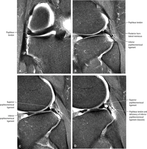 FIGURE 4.140 ● Coronal (A) and sagittal (B) images at the level of the superior popliteomeniscal ligament or fascicle deficiency on a lateral peripheral image. (C) Both inferior and superior fascicles are visualized between the lateral and medial sagittal sections through the hiatus. (D) A more medial section through the hiatus showing the normal inferior popliteomeniscal ligament (fascicle) deficiency. |
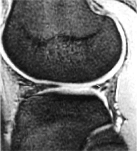 FIGURE 4.141 ● A tear (arrow) of the posterior inferior corner of the lateral meniscus on a T2*-weighted sagittal image. The oblique direction of the tear is opposite to the expected course of the popliteus tendon. The superior meniscal fascicle is intact and is shown in continuity with the posterior horn of the lateral meniscus. |
Popliteal Artery
The popliteal artery within the popliteal fossa neurovascular bundle is located posterior to the posterior horn of the lateral meniscus. If phase and frequency direction are not swapped, pulsation artifacts produce an artificial signal in the area of the posterior horn of the lateral meniscus and obscure accurate visualization of the ACL in the sagittal plane. Phase and frequency are also swapped in the axial plane to improve visualization of the patellofemoral articular cartilage.
Treatment of Meniscal Tears
The following treatment options are available for meniscal injury:
Open meniscal repair, usually appropriate for peripheral tears that occur within 1 to 2 mm of the meniscosynovial junction and involve the posterior third of the medial or lateral meniscus31
Nonoperative treatment, sometimes indicated for partial-thickness split tears that involve less than 50% of the meniscal width and for full-thickness tears less than 5 mm in size with vertical or oblique tear patterns
Meniscectomy, used to treat complex tears, degenerative tears, and large radial and flap tears51
Meniscal transplantation, used to delay the development of degenerative disease after meniscectomy
Meniscal repairs are frequently performed in conjunction with ACL reconstructions because of the association of meniscal tears with ACL-deficient knees. Results of meniscal repairs performed in conjunction with ACL reconstructions are better than those of isolated meniscal repairs. The vascularity of the posterior horn of the lateral meniscus permits repair of complex tears, and injection of a fibrin clot can be used as an adjunct in some cases.122,123 Reparable meniscal tears, including peripheral vertical longitudinal and meniscocapsular injuries, have the following characteristics:
The tear is traumatic.
The tear is located within the peripheral third (the vascular zone) of the meniscus.
There is relative preservation of the body segment of the meniscus.
Peripheral meniscal tears are often associated with hemarthrosis and frequently occur in sports injuries. The medial meniscus is more often affected in football and basketball injuries, whereas the lateral meniscus is more often torn in injuries sustained during wrestling or soccer. Tears involving the avascular zone may not be suitable for repair.
As mentioned, vascular zone tears and unstable peripheral longitudinal vertical tears greater than 1 cm in length, including displaced bucket-handle tears, are candidates for meniscal repair.51 Also, meniscal repair may be appropriate for tears in avascular portions of the meniscus that are in communication with peripheral synovium and perimeniscal capsular plexus. Techniques such as abrasion of the perimeniscal synovium, meniscal rasping, and implantation of exogenous fibrin clots have increased and expanded the criteria for meniscal repair. Most tear types with rim widths of up to 5 mm are considered candidates for meniscal repair, contingent on their ability to be stabilized and coapted. Because of the importance of the lateral meniscus in load transmission, and the potential for severe degenerative disease in patients undergoing total lateral meniscectomy, meniscal repair techniques are usually attempted for most lateral meniscal tears.48 Lateral meniscal tears are also more common in association with acute ACL injuries.
Tears stable to arthroscopic probing (<3 mm of translation on arthroscopic palpation) and short radial tears less than 5 mm in length may not require resection.51 There have been reports of patients in whom certain lateral meniscal tears (posterior horn avulsion tears, vertical tears posterior to the popliteus tendon, and stable vertical longitudinal and radial tears) were identified during ACL reconstruction and who had remained asymptomatic without treatment of their meniscal lesions.124
The decision to perform a partial meniscectomy depends on the morphology of the tear and its extension to the free edge of the meniscus.87 Horizontal tears should not be treated with primary meniscal repair. For longitudinal, vertical, or bucket-handle tears, when meniscal repair is not indicated, a partial meniscectomy is performed in which the displaced portion of the meniscus is reduced with a probe before resection of the meniscus until stable tissue is exposed. A horizontal component is often present at the meniscal rim. Radial tears greater
than 5 mm may be symptomatic and partially resected at arthroscopy. Although usually associated with horizontal tears, meniscal cysts may be associated with deep radial tears. Partial meniscectomy with removal of a flap is performed in oblique tears. The stability of the remaining portion of the meniscus can be tested with a probe at arthroscopy and varies as a function of the horizontal and vertical component to the tear. In horizontal cleavage tears, if one leaf is unstable, it is resected, leaving the stable leaf. A 3-mm flap may be left. In addition, avascular tears and tears associated with unstable ACL-deficient knees in patients older than 40 years are frequently treated by partial meniscectomy.51
than 5 mm may be symptomatic and partially resected at arthroscopy. Although usually associated with horizontal tears, meniscal cysts may be associated with deep radial tears. Partial meniscectomy with removal of a flap is performed in oblique tears. The stability of the remaining portion of the meniscus can be tested with a probe at arthroscopy and varies as a function of the horizontal and vertical component to the tear. In horizontal cleavage tears, if one leaf is unstable, it is resected, leaving the stable leaf. A 3-mm flap may be left. In addition, avascular tears and tears associated with unstable ACL-deficient knees in patients older than 40 years are frequently treated by partial meniscectomy.51
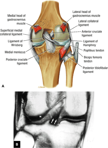 FIGURE 4.142 ● The ligaments of Humphrey and Wrisberg attach the lateral meniscal posterior horn to the medial femoral condyle. Partial insertion of the popliteus tendon into the posterolateral aspect of the lateral meniscus occurs through the superior and inferior fasciculus forming the popliteal hiatus. (B) The ligament of Wrisberg (small arrows) and the PCL (large arrows) are seen on a T1-weighted posterior coronal image. The attachments of the ligament of Wrisberg to the posterior horn of the lateral meniscus (M) and the posteromedial femoral condylae (FC) are evident. |
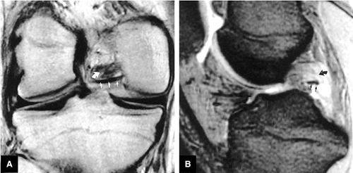 FIGURE 4.143 ● Intermediate-weighted coronal and (B) T2*-weighted sagittal images show the anatomy of the ligament of Humphrey (straight arrows). A complete tear of the PCL (curved arrow) is also present. |
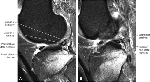 FIGURE 4.144 ● Sagittal FS PD FSE images of the normal meniscofemoral ligaments without a meniscal tear. (A) The ligaments of Humphrey and Wrisberg can be seen posterior to the posterior horn of the lateral meniscus. (B) On next medial sequential image through the lateral compartment, the ligament of Wrisberg courses superiorly to pass posterior to the PCL within the intercondylar notch. The hyperintense interface between the lateral meniscus and meniscofemoral ligament is normal, even though a fracture of the posterior lateral tibial plateau can be seen on this image. |
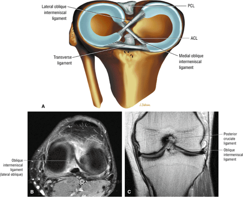 FIGURE 4.145 ● The course of the oblique intermeniscal ligaments can be seen from the anterior horn of the medial meniscus to the posterior horn of the lateral meniscus. (A) Superior view of both oblique meniscal ligaments. (B) Axial FS PD FSE image. (C) Anterior coronal PD FSE image. |
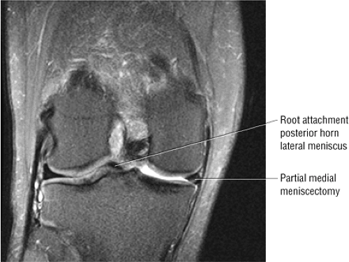 FIGURE 4.146 ● The posterior root attachment of the lateral meniscus is often mistaken for a displaced meniscal fragment, including a bucket-handle tear. Incidental post-partial meniscectomy changes are also seen in the medial meniscus, which is foreshortened and has residual grade 3 signal intensity (coronal FS PD FSE image). |
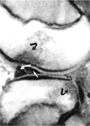 FIGURE 4.147 ● The posterior horn of the lateral meniscus (open arrow) is displaced toward (straight arrow) the anterior horn of the lateral meniscus (curved arrow). Trabecular bone contusions are of low signal intensity relative to the adjacent bright fatty marrow epiphysis on a T1-weighted sagittal image. |
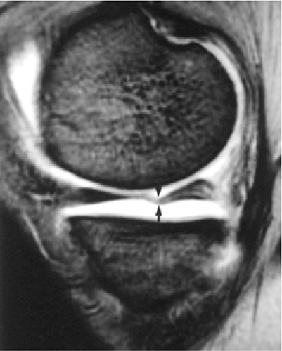 FIGURE 4.148 ● T2*-weighted medial sagittal image demonstrates that a wavy folded contour may be a normal variant of the intact meniscus. |
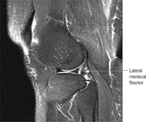 FIGURE 4.149 ● Less common lateral meniscal flounce on FS PD FSE sagittal image. |
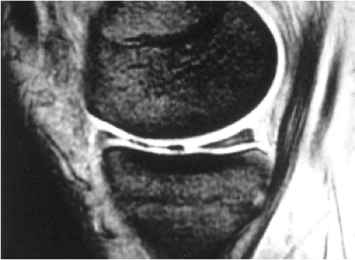 FIGURE 4.150 ● The vacuum phenomenon. Normal intra-articular gas is identified as a signal void between the femoral and tibial articular cartilage. This T2*-weighted sagittal image demonstrates blooming of the signal void from magnetic susceptibility of the intra-articular gas. |
 FIGURE 4.151 ● FS PD FSE sagittal image displaying the normal medial meniscocapsular attachment with an intact meniscus–capsular interface junction at the periphery of the posterior horn of the meniscus. |
Meniscal Transplantation
Meniscal transplantation, developed by Garrett et al., is used to delay the development of degenerative disease after meniscectomy.125 In this procedure, age- and size-matched allograft menisci are sutured to the resected meniscal rim. The anterior and posterior meniscal horn and meniscotibial attachments are preserved so that they can function as firm anchors for the generation of hoop stresses. Accurate restoration of the meniscal horns is achieved with the use of bony plugs or blocks. This procedure is primarily used in young patients who have undergone total meniscectomy and who are likely to develop degenerative arthrosis by middle age. Ideal patients for meniscus transplantation should meet the following criteria:
Documented near-complete meniscectomy
Ligamentous stability
Early (grades I to II) chondral degeneration
Intact osseous alignment and congruence of articular cartilage126
Degenerative arthrosis develops more rapidly after lateral meniscectomy than after medial meniscectomy, and patients with significant joint space narrowing and chondral loss are not candidates for meniscal replacement.
Meniscal transplantation also contributes to stability in ACL-deficient knees with absent medial menisci and fibrocartilage. It may also contribute to preservation of joint function as part of a three-stage reconstruction that includes the repair of the meniscus, the ACL, and any associated osteochondral lesion.
MR is used preoperatively to evaluate the meniscal remnant, to determine proper sizing, and to identify associated chondral erosions. Postoperatively, MR is used to evaluate the integrity of the transplant and allograft and to follow peripheral healing at the suture site. During the process of peripheral revascularization after meniscal transplantation, persistent grade 3 signal intensity may be seen (Fig. 4.152).
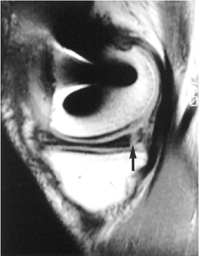 FIGURE 4.152 ● A T1-weighted sagittal image shows that peripheral grade 3 signal intensity (arrow) in a postmeniscal transplant represents suture attachment with healing, not a vertical tear. |
Postoperative Appearance of the Meniscus
Pearls and Pitfalls
Postoperative Meniscus
Grade 3 signal intensity should not be mistaken for residual tear or retear in a stable meniscal remnant after partial menisectomy.
Selective blunting of the inferior surface (leaf) is associated with partial meniscectomy of tears extending to the inferior articular surface of the meniscus.
Stable meniscal fibrovascular scars are intermediate in signal intensity on FS PD FSE images. Direct linear extension of hyperintense fluid or intra-articular contrast, however, represents retear of the meniscal repair or extension of the tear into an unstable meniscal remnant.
MR arthrography is primarily used to evaluate post-primary repair menisci and in cases of more extensive partial menisecectomies.
The postoperative evaluation of partial meniscectomies and primary repair offers unique challenges for MR imaging (Fig. 4.153). Correlation of MR findings with preoperative MR studies or details of the arthroscopic surgery is useful in increasing the accuracy of MR diagnosis of a retear or persistent tear or a normal healing response to the meniscal fibrocartilage. It may be difficult to identify tears in the meniscal remnants after a partial meniscectomy. The free edge of the inferior leaf may be preferentially resected in tears demonstrating inferior surface extension (Fig. 4.154).
MR Appearance After Meniscectomy
Even in the absence of a retear, the meniscal remnant may demonstrate a residual grade 3 signal intensity, also referred to as intrameniscal signal conversion (Fig. 4.155). FS PD FSE or T2* GRE (although the latter is subject to increased susceptibility artifact, as discussed below) images can be used to identify fluid directly extending into the cleavage plane of a tear in a meniscal remnant (Fig. 4.156). This finding is more
specific than the presence of grade 3 signal intensity on short-TE or T1-weighted images. A meniscal cyst may be associated with an unstable or symptomatic meniscal remnant or post-repair meniscus. A sharp, blunt, surgical truncation of the apex of the meniscus with foreshortening is often seen with partial meniscectomy. The meniscal tissue, however, may be contoured so that the remnant does not show obvious blunting (Fig. 4.157).
specific than the presence of grade 3 signal intensity on short-TE or T1-weighted images. A meniscal cyst may be associated with an unstable or symptomatic meniscal remnant or post-repair meniscus. A sharp, blunt, surgical truncation of the apex of the meniscus with foreshortening is often seen with partial meniscectomy. The meniscal tissue, however, may be contoured so that the remnant does not show obvious blunting (Fig. 4.157).
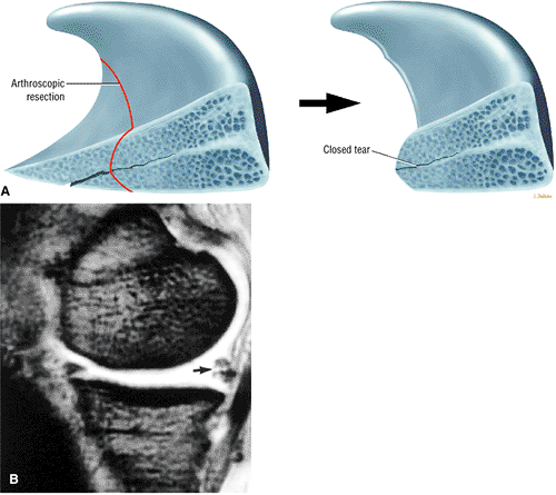 FIGURE 4.153 ● Boundary of partial meniscectomy to a stable meniscal rim. Residual degeneration or a closed tear is left to preserve the surrounding meniscal tissue. (B) T2*-weighted image shows normal residual grade 3 signal intensity (arrow) in a partial remnant from a posterior horn medial meniscectomy. This intensity does not represent a retear in this stable meniscal rim. |
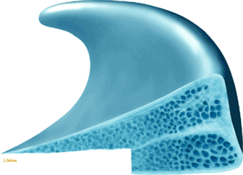 FIGURE 4.154 ● Preferential resection of inner margin of inferior leaf (leaflet) in partial meniscectomy. |
Residual signal intensity may also occur if one or both leaves of a cleavage component of a tear are removed. MR accurately demonstrates the degree of partial meniscectomy from less than 25% (Fig. 4.158) to 75% (Figs. 4.159 and 4.160) or greater. We have successfully used FS PD-weighted FSE images to display the morphology of the postoperative meniscus with decreased magnetic susceptibility artifact in comparison with GRE techniques. It is important, however, to recognize the limitation of FSE technique in accurately identifying intrameniscal signal intensity, and it should be used in conjunction with either FS PD conventional spin-echo or GRE images.
Postoperative meniscal fragments adjacent to the site of a meniscectomy may also be identified with MR imaging, especially using techniques of FSE with FS or conventional T2 spin-echo images. After meniscectomy, increased contact stress and elastic modulus between the femur and the tibia place the articular cartilage at risk of injury (Fig. 4.161), and the meniscal remnants are less effective in diffusing loads to a greater area of the knee joint.
No meniscal tissue is seen after a total meniscectomy; the joint space left after removal of fibrocartilage may be filled with fluid. Additional MR findings after partial or complete meniscectomy may include progressive joint space narrowing with articular cartilage loss (Fig. 4.162) and subchondral low signal intensity in the involved compartment before the appearance of plain-film sclerosis. The lateral compartment is especially at risk for arthrosis after partial or complete meniscectomy. Subchondral changes may display hypointensity on T1 or PD FSE images and hyperintensity on corresponding STIR or FS PD FSE images during stages of reactive hyperemia. Flattening or posterior ridging of the femoral condyles and tibial marginal spurring and sclerosis (indicative of previous meniscectomy) are chronic findings (Figs. 4.163 and 4.164).51
Smith et al. have divided the MR characteristics of partial meniscectomy into three groups.127 Group 1 menisci demonstrate near-normal length and no osteoarthritis. Group 2 menisci are significantly shortened but do not show osteoarthritis. Group 3 menisci may be any length, but they demonstrate the development of osteoarthritis. In group 2 menisci, contour irregularities simulated meniscal fragmentation in 40% of segments studied; therefore, no rigid criteria for diagnosis of tearing in meniscal segments with partial meniscectomy contour irregularities were established in this study. Regenerated meniscal tissue (i.e., rim) is composed of fibrous tissue, is smaller than normal, and demonstrates low to intermediate signal intensity on T1-, PD, T2-, or T2*-weighted images.
Accurate correlation of the original tear pattern with the extent of the meniscectomy increases the usefulness of the finding of grade 3 signal intensity as an indicator of retear. An increased prevalence of radial tears has been observed in postoperative partial meniscectomy remnants and is attributed to the altered hoop mechanism of the meniscus secondary to meniscal resection.128
The accuracy of MR diagnosis of recurrent tears in the postoperative meniscus may be improved with MR arthrography (Fig. 4.165).129 MR arthrography is useful in patients with meniscal resections of greater than 25%, provided that native
joint fluid does not already extend into the meniscus. MR arthrography is not necessary in patients with minimal meniscal resection (< 25%).130,131,132
joint fluid does not already extend into the meniscus. MR arthrography is not necessary in patients with minimal meniscal resection (< 25%).130,131,132
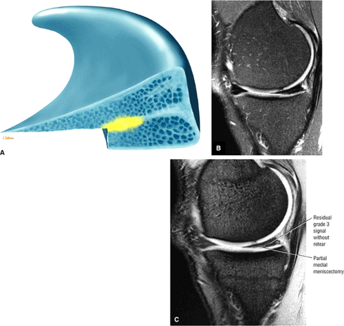 FIGURE 4.155 ● Partial meniscectomy. (A) Residual meniscal degeneration (yellow). Corresponding partial medial meniscectomy posterior horn fibrocartilage on FS PD FSE (B) and T2* GRE (C) sagittal images. Residual grade 3 signal is best visualized with GRE T2* contrast. |
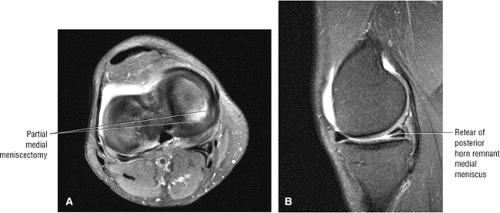 FIGURE 4.156 ● (A) Axial image showing post-partial medial meniscectomy. (B) Corresponding FS PD FSE sagittal image showing retear of the meniscal remnant. |
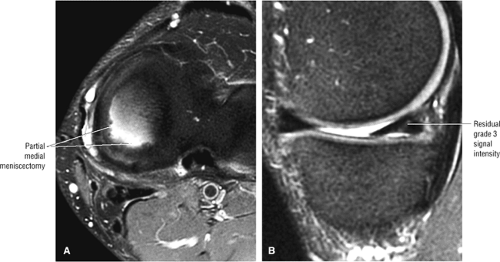 FIGURE 4.157 ● Contoured free edge (A) and inferior leaflet (B) after partial medial meniscectomy. Residual intrasubstance meniscal signal is present without retear. (A) Axial FS PD FSE image. (B) Sagittal FS PD FSE image. |
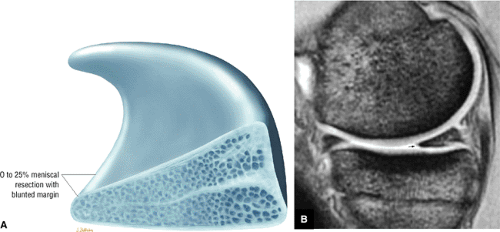 FIGURE 4.158 ● Mild free edge blunting after a minimal or micro-partial meniscectomy. (A) Sagittal cross-sectional illustration. (B) Corresponding FS PD FSE sagittal image. |
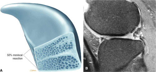 FIGURE 4.159 ● Fifty percent meniscal resection with blunted free edge. (B) Corresponding FS PD FSE sagittal image demonstrates persistence of grade 3 signal intensity (arrows) in the posterior horn remnant of the lateral meniscus. |
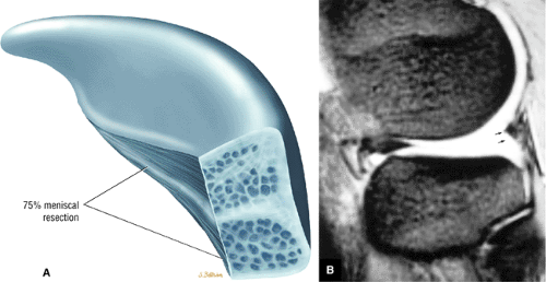 FIGURE 4.160 ● (A) Cross-sectional sagittal illustration of a 75% resection of posterior horn lateral meniscus with a thick rim of meniscal remnant. (B) Corresponding T2* GRE sagittal image. |
MR Appearance After Meniscal Repair
Primary meniscal repairs may show grade 1, grade 2, or persistent grade 3 signal intensity on postoperative MR (Fig. 4.166).133,134,135 Second-look arthroscopy has shown that healed meniscal repair may demonstrate grade 3 signal intensity, making postoperative characterization of primary repairs difficult.134 However, the criteria for retear of a primal meniscal repair are similar to those for a partial meniscectomy remnant. Signs of retear include:
Hyperintensity at the repair site on FS PD- or T2-weighted images
Displaced meniscal fragments
Increased signal intensity at a new location or site relative to the repair136
Intra-articular gadolinium may be helpful in identifying imbibed synovial fluid extending into menisci that are retorn after primary repair (see Fig. 4.165), according to the same principle underlying the use of long-TE or T2-weighted images to identify the direct extension of fluid into the cleavage plane of a tear to help increase diagnostic accuracy. Both IV and intra-articular gadolinium have been used to improve characterization of recurrent tears and meniscal surfaces (Fig. 4.167).30,137
Correlation of MR findings with second-look arthroscopic examination of post-primary repair menisci has shown that there may be conversion of grade 3 signal intensity into lower grades of signal intensity, primarily in areas of fibrovascular healing, which corresponds with the conversion of granulation or scar tissue to normal fibrocartilage (Fig. 4.168). This process occurs over a period of months. Arnoczky et al. evaluated MR signals in healing menisci in dogs.133 They found that in full-thickness radial tears, the normal fibrovascular scar tissue or repair tissue generated increased signal intensity on MR that persisted at 26 weeks, even though this fibrovascular repair tissue had converted from scar into fibrocartilage. This study supports the observation that normal fibrovascular repair tissue as well as conversion of fibrovascular repair tissue to fibrocartilage may demonstrate persistent grade 3 signal intensity in healing menisci. The findings by Deutsch et al. of persistent signal intensity up to 27 months postoperatively demonstrate that the conversion process from fibrovascular tissue to fibrocartilage is protracted and may even be chronic.134 Intact meniscal fibrovascular scars are intermediate in signal on FS PD FSE images and maintain intermediate signal without allowing extension of intra-articular gadolinium-based contrast on corresponding MR arthrography.
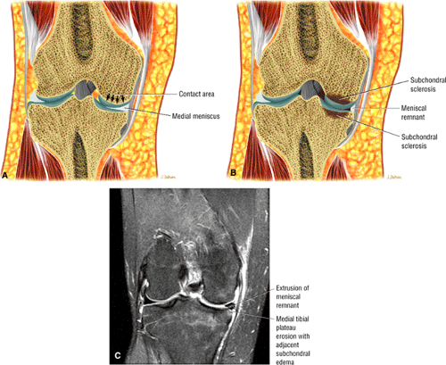 FIGURE 4.161 ● (A) A large contact area between the medial femoral condyle and the tibial plateau allows normal load transference to the intact meniscus. (B) Loss of the condylar meniscus contact area results in focally concentrated stress and medial compartment arthrosis after a partial meniscectomy. (C) Coronal FS PD FSE image shows extrusion of a meniscus remnant and erosion of the medial tibial plateau. |
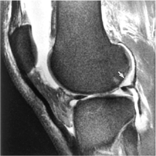 FIGURE 4.162 ● Loss of lateral femoral condyle articular cartilage (arrow) opposite the lateral meniscus posterior horn remnant shown on a FS T2-weighted FSE sagittal image. |
Miscellaneous Meniscal Pathology
Meniscocapsular Separations
Pearls and Pitfalls
Meniscocapsular Separations
The meniscocapsular ligaments consist of meniscofemoral and meniscotibial ligaments and are defined in layer 3 of the knee joint capsule.
Tears of the proximal MCL are associated with meniscofemoral ligament injuries.
Fluid interposed between the meniscus and capsular periphery posterolateral to the superficial MCL and deep MCL represents a form of meniscocapsular tearing and may be associated with a posterior medial meniscal corner tear in acute ACL injuries.
Meniscal avulsions involving the meniscotibial attachment occur in both the medial and lateral meniscus.
Meniscocapsular separations or tears usually involve the less mobile medial meniscus.115 The thick medial third of the joint
capsule or medial capsular ligament is divided into meniscofemoral and meniscotibial components (Fig. 4.169).138,139 Anteriorly these fibers are separated from the superficial fibers of the MCL by an interposed bursa and can best be seen on routine FS PD FSE radial images through the medial compartment of the knee. Most protocols do not routinely use radial images, however, since routine orthogonal FS PD FSE images are usually sufficient. The posterior horn of the medial meniscus, fixed to the tibia by meniscotibial or coronary ligaments, is especially susceptible to tearing at its capsular attachment. Even in the absence of grade 3 signal intensity through the meniscus, a separation at the meniscocapsular junction associated with pain may have clinical significance. Small or nondisplaced meniscocapsular tears may heal without surgical intervention because these tears occur through the vascularized periphery of the meniscus, adjacent to the perimeniscal capillary plexus.68 Minor repair of these lesions also has a high success rate because of their peripheral location.
capsule or medial capsular ligament is divided into meniscofemoral and meniscotibial components (Fig. 4.169).138,139 Anteriorly these fibers are separated from the superficial fibers of the MCL by an interposed bursa and can best be seen on routine FS PD FSE radial images through the medial compartment of the knee. Most protocols do not routinely use radial images, however, since routine orthogonal FS PD FSE images are usually sufficient. The posterior horn of the medial meniscus, fixed to the tibia by meniscotibial or coronary ligaments, is especially susceptible to tearing at its capsular attachment. Even in the absence of grade 3 signal intensity through the meniscus, a separation at the meniscocapsular junction associated with pain may have clinical significance. Small or nondisplaced meniscocapsular tears may heal without surgical intervention because these tears occur through the vascularized periphery of the meniscus, adjacent to the perimeniscal capillary plexus.68 Minor repair of these lesions also has a high success rate because of their peripheral location.
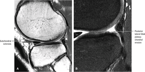 FIGURE 4.163 ● Partial lateral meniscectomy. (A) Sagittal PD FSE image showing early superficial surface subchondral sclerosis of the posterior lateral compartment. (B) Sagittal FS PD FSE image depicting chondral erosion subsequent to partial lateral meniscectomy. |
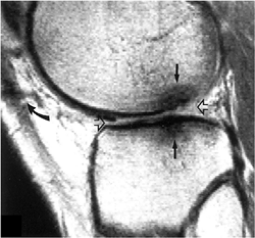 FIGURE 4.164 ● Lateral compartment arthrosis with advanced degenerative changes after lateral meniscectomy (open arrows). Hypointense subchondral sclerosis is demonstrated (closed arrows). Arthroscopy tract is seen anteriorly. |
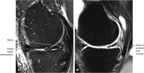 FIGURE 4.165 ● MR arthrogram. Retear of posterior horn remnant showing increased conspicuity of contrast between FS PD FSE (A) and FS T1-weighted (B) sagittal images. The meniscal extension of intra-articular contrast is best visualized on the FS T1-weighted image. |
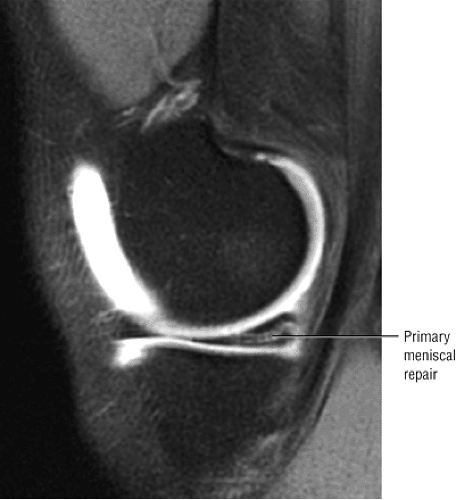 FIGURE 4.166 ● Primary meniscal repair with intrasubstance signal intensity not extending to an articular surface (sagittal FS T1 MR arthrogram image). |
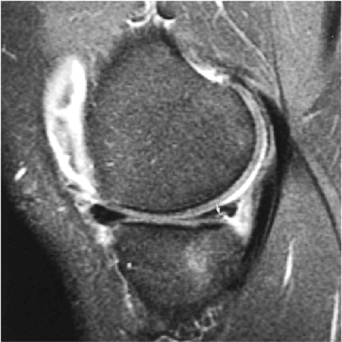 FIGURE 4.167 ● IV gadolinium enhancement facilitates identification of grade 3 signal intensity (arrow) extending to the irregular inferior surface of the postoperative meniscus on a FS T1-weighted image. |
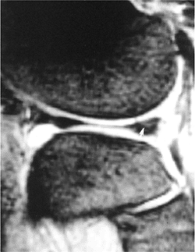 FIGURE 4.168 ● A T2*-weighted sagittal image made after primary repair of the lateral meniscus shows minimal residual signal intensity in the posterior horn. |
On sagittal MR images, the tibial plateau articular cartilage should be covered by the posterior horn of the medial meniscus without an exposed articular cartilage surface. Displacement of the posterior horn of the medial meniscus by 5 mm or more, uncovered tibial articular cartilage, and fluid interposed between the peripheral edge of the meniscus and capsule are suggestive of peripheral detachment.68 Uncovering of the tibial articular cartilage, however, is not a specific sign for meniscocapsular injury, and quantitative measurements of meniscal displacement may be unreliable. In addition, the
meniscus may have fluid within the superior and inferior capsular recesses without violation of the meniscocapsular junction. In true meniscocapsular separations, especially in association with ACL tears, sagittal images demonstrate fluid completely interposed between the peripheral portion of the posterior horn of the medial meniscus and the joint capsule (Fig. 4.170). Coronal and sagittal images best display the anatomy of the deep capsular layer and its relation to the meniscus for identification of disruptions of the meniscofemoral and meniscotibial ligaments.
meniscus may have fluid within the superior and inferior capsular recesses without violation of the meniscocapsular junction. In true meniscocapsular separations, especially in association with ACL tears, sagittal images demonstrate fluid completely interposed between the peripheral portion of the posterior horn of the medial meniscus and the joint capsule (Fig. 4.170). Coronal and sagittal images best display the anatomy of the deep capsular layer and its relation to the meniscus for identification of disruptions of the meniscofemoral and meniscotibial ligaments.
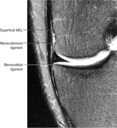 FIGURE 4.169 ● Coronal FS PD FSE image showing the medial meniscofemoral and meniscotibial ligaments proximal and distal, respectively, to the lateral joint line. |
MCL tears may also be seen in association with meniscocapsular separation. Figure 4.171 illustrates displacement of the meniscofemoral ligament from its femoral attachment in association with a proximal grade 3 MCL tear. Complete peripheral detachment of the posterior horn is seen as a free-floating meniscus, especially if it is associated with a MCL tear. The interface between the posterior horn of the medial meniscus and posteromedial capsular tissue should be identified and defined on all sagittal images. Fluid extending completely across this interface (superior to inferior) or across the meniscotibial capsular attachment is an abnormal finding (Fig. 4.172). In the posteromedial aspect of the knee, the capsule fuses with the gastrocnemius tendon superiorly and also attaches to the cortex of the posterior femoral condyle. A subgastrocnemius bursa is formed between the capsule and the gastrocnemius tendon.140
In acute ACL tears, posterior inferior corner tears of the medial meniscus are frequently seen in association with posteromedial medial tibial osseous contusion or fractures. In the setting of an ACL tear, such peripheral tears are caused by contre-coup forces resulting from direct contact between the medial femoral condyle and medial tibial plateau subsequent to impaction between the sulcus terminals of the lateral femoral condyle and the posterolateral tibial plateau (see Fig. 4.172). This area of meniscocapsular interface is more posterior and lateral (toward the notch) than the portion of layer 3 referred to as the deep MCL.
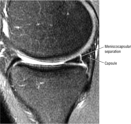 FIGURE 4.170 ● Sagittal PD FSE image showing complete meniscocapsular separation at the interface of the posterior horn of the medial meniscus and the peripheral capsular tissue. Hypointense thick capsular tissue should not be mistaken for meniscal fibrocartilage. |
Meniscal avulsion from the tibial plateau is associated with disruption of the meniscotibial attachment of the deep capsular layer (Fig. 4.173). The term floating meniscus describes the resultant appearance of fluid surrounding the detached meniscus in the setting of acute trauma with discontinuity of the meniscotibial capsular ligament (see Fig. 4.173).141 As the meniscofemoral ligament is usually intact in this setting, the prominent layer of fluid is localized between the meniscus and the tibial plateau. A “floating meniscus” may involve either the medial or lateral meniscus. A distal MCL tear may preferentially disrupt the meniscotibial ligament (Fig. 4.174).
Meniscal Cysts
Pearls and Pitfalls
Meniscal Cysts
Meniscal cysts are related to either microscopic or macroscopic tears in meniscal fibrocartilage.
Horizontal cleavage tears or complex meniscal tears with a horizontal component are associated with the development of meniscal cysts.
Loculations, septations, and dissection of the cyst from the site of origin are common findings.
Meniscal cysts (also referred to as ganglion cysts, a nonspecific and less descriptive term) have been reported in 1% of
meniscectomies.8,26 They are classified into three types: intrameniscal, parameniscal, and synovial cysts:
meniscectomies.8,26 They are classified into three types: intrameniscal, parameniscal, and synovial cysts:
Intrameniscal cysts are uncommon and represent intrameniscal fluid collections in continuity with meniscal tears.
Parameniscal cysts are more common and most frequently present as loculated or simple fluid collections located at the periphery of the meniscus, often with a horizontal cleavage tear pattern on cross-section (Fig. 4.175).
Synovial cysts are rare and are not associated with meniscal tears. They represent cystic outpouching of the joint capsule.26
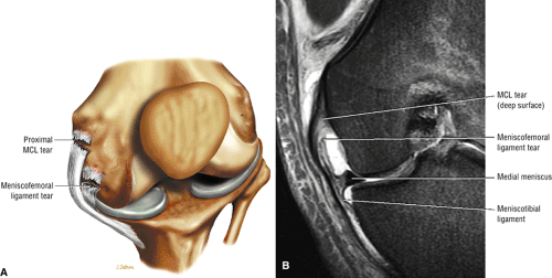 FIGURE 4.171 ● Coronal illustration (A) and FS PD FSE image (B) showing meniscofemoral ligament disruption in association with a proximally located MCL sprain. |
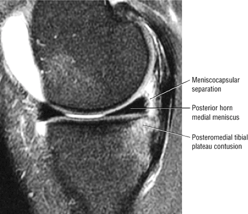 FIGURE 4.172 ● Medial meniscus meniscocapsular separation with a complete plane of fluid separating the posterior horn and posterior capsular tissues. This injury occurs posterior to and closer to the intercondylar notch than do deep capsular ligament (deep MCL) injures, which are associated with superficial MCL tears. Contre-coup forces during an ACL tear produce this injury and contusion of the posteromedial tibial plateau (sagittal FS PD FSE image). |
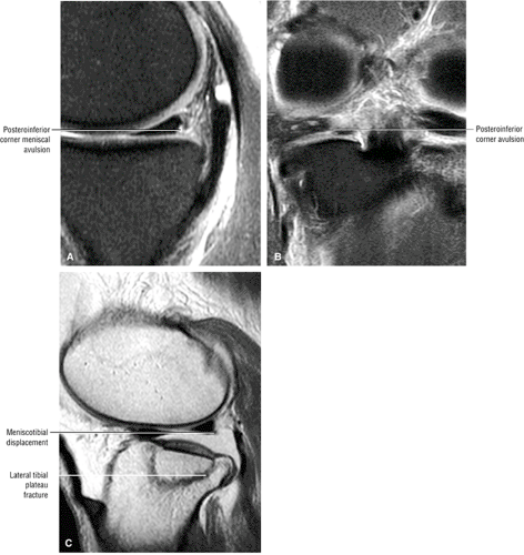 FIGURE 4.173 ● Posteroinferior medial meniscus corner avulsion at the meniscotibial ligament attachment site on FS PD FSE sagittal (A) and coronal (B) images. (C) Separate case with a “floating lateral meniscus” associated with a lateral tibial plateau fracture and disruption of the meniscotibial attachment. |
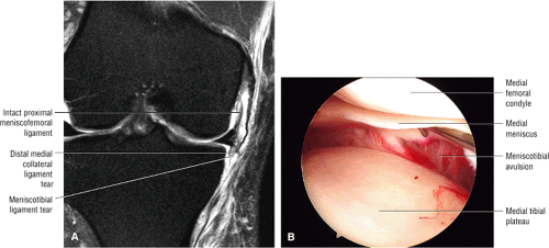 FIGURE 4.174 ● (A) A coronal FS PD FSE image demonstrating distal MCL avulsion associated with avulsion of the meniscotibial ligament. (B) Corresponding arthroscopic view shows a meniscotibial tear of the deep capsular layer of the MCL located between the elevated medial meniscus and medial tibial plateau. |
Parameniscal cysts usually present at the level of the joint line, either as a focal mass or a swelling. They may develop in response to trauma or degeneration and are associated with meniscectomy.142,143 One theory holds that injuries or trauma generate tangential or compressive forces that initiate necrosis in the central peripheral aspect of the meniscus, leading to mucoid degeneration and cyst development. Lateral parameniscal cysts are three to seven times more common than medial cysts, and they often present at the medial third of the peripheral margin of the meniscus. The difference in the prevalence of lateral and medial meniscal cysts may be exaggerated because of underreporting of medial cysts, which are less likely to cause symptoms. Diagnostic use of MR for meniscal lesions should provide more accurate statistics about these cysts.144
Medial meniscal cysts may dissect through soft tissue (i.e., joint capsule and MCL) and often present in a different location than the meniscus tear origin (Fig. 4.176). They are frequently found deep to the MCL or in the posteromedial corner, deep to the posterior oblique ligament. If there is peripheral propagation of mucoid degeneration, the medial meniscus may appear intact in the presence of an associated external cyst. Pericruciate meniscal cysts may arise from tears of the posterior horn of the medial meniscus and may be mistaken for a posterior cruciate ganglion cyst.145 Small meniscal cysts also occur in asymptomatic knees.146 Medial meniscal cysts can been seen extending from the posterior horn and dissecting peripherally to present in a more anterior location. A thin stalk in continuity with the meniscus can usually be identified in these cases. A horizontal meniscal tear, a flap tear with a primarily horizontal component, or a complex tear frequently communicates with a meniscal cyst with decompression of synovial fluid.
In 90% of cases, lateral meniscal cysts are also associated with a horizontal flap tear, a horizontal cleavage tear, or a complex tear with horizontal and radial components. Lateral meniscal cysts are usually located anterior to the LCL or between the LCL and popliteus tendon. Discoid lateral menisci are associated with fibrocartilaginous cavitary lesions (prominent grade 2 signal) and parameniscal cyst development (Fig. 4.177). Large meniscal cysts usually present as painful, palpable masses near the joint line. A palpable mass that disappears with knee flexion is known as Pisani’s sign. Lateral meniscal cysts tend to be larger than medial cysts because the soft tissue constraints tend to be looser than on the medial side (Fig. 4.178).
Meniscal cysts are uniformly low in signal intensity on T1-weighted images and increase in signal intensity on FS PD-weighted FSE images, T2* GRE images, or STIR images.
Because cysts may also contain bloody or gelatinous fluid with an increased protein content, there may be some variation in their signal-intensity properties on T2-type sequences relative to the appearance and imaging characteristics of free synovial fluid. Loculations or septations may be seen, especially in complex meniscal cysts, usually in those cysts removed in distance from their site of origin (meniscal tear). Erosion of the adjacent tibial condyle may occur with large, untreated lateral meniscal cysts.
Because cysts may also contain bloody or gelatinous fluid with an increased protein content, there may be some variation in their signal-intensity properties on T2-type sequences relative to the appearance and imaging characteristics of free synovial fluid. Loculations or septations may be seen, especially in complex meniscal cysts, usually in those cysts removed in distance from their site of origin (meniscal tear). Erosion of the adjacent tibial condyle may occur with large, untreated lateral meniscal cysts.
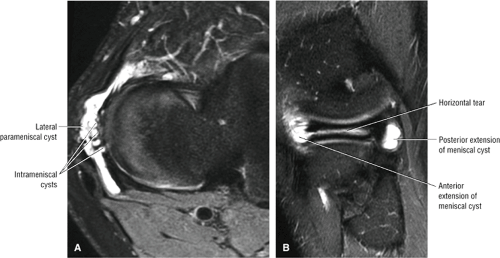 FIGURE 4.175 ● Lateral meniscus horizontal tear decompressing fluid into a series of intrameniscal cysts communicating with a larger peripheral parameniscal cyst. Anterior-to-posterior extension of the parameniscal cyst is shown on axial (A and sagittal (B FS PD FSE images. |
The differential diagnosis of parameniscal cysts includes:
Osteophytic spurring
Synovial cysts
Proximal tibiofibular cysts
Traumatic bursitis
Masses (including pigmented villonodular synovitis, hemangioma, lipoma, and synovial sarcoma)147
Although aggressive malignant lesions such as synovial sarcomas may show hyperintensity on T2-weighted images, they tend to have a lower and more inhomogeneous signal intensity than that of synovial fluid. Sometimes synovial sarcomas mimic the appearance of a hemorrhagic or highly proteinaceous fluid collection. IV gadolinium contrast peripherally enhances a meniscal cyst in comparison to the more centralized enhancement of a soft tissue neoplasm.
Treatment for meniscal cysts is arthroscopic resection and repair of the tear.
Calcium Pyrophosphate Dehydrate Deposition Disease
Pearls and Pitfalls
Calcium Pyrophosphate Dehydrate Deposition Disease
T2* GRE images are recommended for detection of punctate hypointense CPPD crystal depositions.
High contrast settings help identify meniscal tissue involvement.
Meniscal degeneration and tears may be underestimated secondary to localized susceptibility effects induced by crystal deposition, especially on T2* GRE images.
In calcium pyrophosphate dehydrate deposition disease (CPPD), there is deposition of calcium pyrophosphate crystals in hyaline cartilage, synovial tissue, capsule, and/or meniscus. CPPD presents with the clinically separate yet related syndromes of:
Pseudogout, in which there is no urate, as is found in true gout
Tophaceous pseudogout, which produces pseudotumors
Familial CPPD, which is rare in the knee and presents at an earlier age
Pyrophosphate arthropathy, both osteoarthritic and neuropathic forms
Chondrocalcinosis, which is asymptomatic
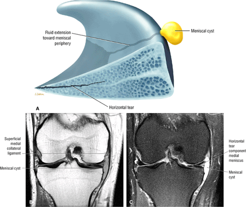 FIGURE 4.176 ● Peripheral meniscal cyst formation in continuity with horizontal tear. (A) Sagittal cross-section with parameniscal cyst in yellow. (B) Coronal PD FSE image. (C) Coronal FS PD FSE image. |
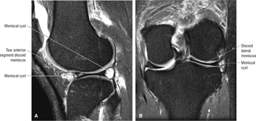 FIGURE 4.177 ● FS PD FSE sagittal (A) and coronal (B) images showing a discoid lateral meniscus forming fluid- and synovium-containing parameniscal cyst. |
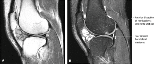 FIGURE 4.178 ● A large septated and multilobulated lateral parameniscal cyst dissecting freely into Hoffa’s fat pad as seen on sagittal PD FSE (A), sagittal FS PD FSE (B), and axial FS PD FSE images. |
In chondrocalcinosis, meniscal calcifications are usually identified with conventional radiographic techniques. In patients with calcium pyrophosphate disease, MR studies using high contrast settings for photography reveal focal, low-signal-intensity calcifications separate from adjacent low-signal-intensity meniscus. On T2*-weighted images, local susceptibility artifacts are seen around the foci of calcium pyrophosphate deposition, making them easier to identify (Fig. 4.179). Because of local magnetic susceptibility, however, crystals resulting from calcium pyrophosphate disease in either the meniscus or articular cartilage may dampen the signal intensity for meniscal degenerations and tears, falsely producing grade 2 signal intensity in cases in which there is grade 3 signal intensity on corresponding T1- or PD-weighted images (Fig. 4.180). Chondrocalcinosis, therefore, is more difficult to identify on non-GRE sequences. Conversely, increased signal intensity directly attributed to the effect of chondrocalcinosis may also decrease MR accuracy by producing false-positive tears on GRE sequences.148
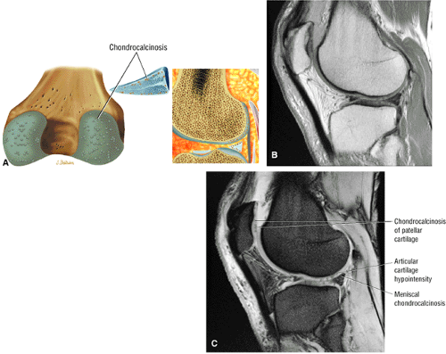 FIGURE 4.179 ● Chondrocalcinosis affecting both the articular cartilage and meniscus. (A) Posterior coronal and sagittal (lateral) cross-section illustration. PD-weighted (B) and T2* GRE (C) sagittal images. The conspicuity of hypointense crystal deposition susceptibility is improved on the GRE image (C). |
Dicalcium phosphate dihydrate, hydroxyapatite, and calcium oxalate are also responsible for cartilaginous calcifications.43 A meniscal ossicle is larger and occurs as an isolated focus in asymptomatic patients without a history of antecedent trauma (Fig. 4.181).133 On MR, the marrow-containing corticated ossicle can be seen within the posterior horn of the medial meniscus.
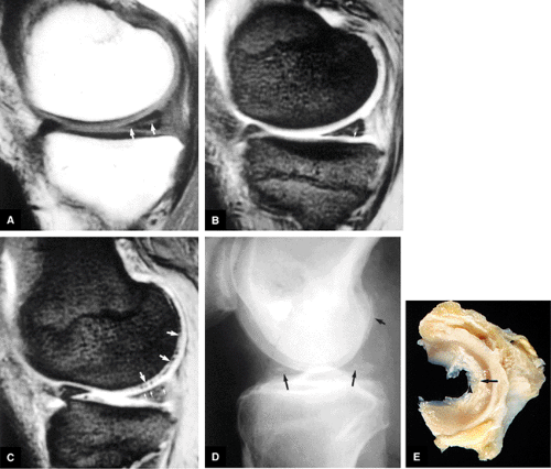 FIGURE 4.180 ● Chondrocalcinosis. (A) On a T1-weighted sagittal image the posterior horn of the medial meniscus shows grade 3 signal intensity (arrows). (B) On the corresponding T2*-weighted sagittal image, chondrocalcinosis dampens the meniscal signal intensity (arrow) as a result of localized magnetic susceptibilities. (C) On a T2*-weighted sagittal image through the lateral compartment, multiple foci of deposition resulting from calcium pyrophosphate disease are evident within the articular cartilage (large arrows) and the meniscus (small arrows). (D) On the corresponding lateral radiograph, chondrocalcinosis is evident in a region of meniscal fibrocartilage (large arrows) and articular cartilage (small arrow). (E) On a gross meniscal specimen, deposition resulting from chondrocalcinosis is seen in the lateral meniscus (arrow). Degenerative free edge of the meniscus is shown (arrowhead). |
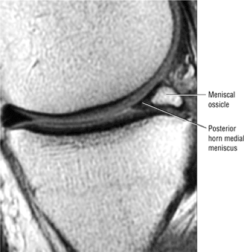 FIGURE 4.181 ● The meniscal ossicle (curved arrow) shows bright marrow-fat signal intensity on a T1-weighted sagittal image (left) and low signal intensity on a T2*-weighted sagittal image (right). The blunted apex of the posterior horn (straight arrow) is indicated. A popliteal cyst is seen with increased signal intensity on the T2*-weighted sagittal image (open arrow). |
Cruciate Ligaments
Anterior Cruciate Ligament
Functional Anatomy
Pearls and Pitfalls
Anterior Cruciate Ligament
The ACL is a two-bundle ligament with a small anteromedial and a larger posterolateral (tight in extension) bundle. Functional ACL fiber recruitment, however, is more complicated than assignment to one of two fiber bundles.
The ACL is the primary restraint to anterior tibial displacement, with the posterolateral bundle providing the principal resistance to hyperextension forces.
The cruciate ligaments are intracapsular and extrasynovial. The ACL and PCL are enveloped by a fold of synovium that takes origin from the posterior intercondylar area of the knee.149 Proximally, the ACL is attached to a fossa on the posteromedial aspect of the lateral femoral condyle.138,149 At its origin, the ACL is 16 to 24 mm in diameter, located posteriorly within the intercondylar notch.149 Distally the ACL extends inferior and medial to the anterior tibial intercondylar area and attaches to a fossa anterior and lateral to the anterior tibial spine, between the anterior attachments of the menisci (Fig. 4.182). The center of origin of the ACL is 15 mm from the junction of the posterior femoral shaft and the proximal aspect of the lateral femoral condyle (defined as the over-the-top position). This over-the-top position is a critical landmark in the placement of the femoral tunnel when reconstructing the ACL. The ACL is 11 mm wide and 31 to 38 mm long.20 The tibial attachment of the ACL (broader or larger than the femoral attachment) passes deep to the transverse ligament of the knee.149 It begins as the ACL starts to fan out in its proximal third. Ligamentous branches of the middle geniculate artery form a vascular plexus that supplies both the ACL and PCL (Fig. 4.183).
The individual fascicles of the ACL are divided into two functional fiber bundles (the anteromedial and posterolateral bands [AMB and PLB]) that do not exist as distinct structures on gross examination (Fig. 4.184).149,150,151 The longer and stronger AMB tightens with knee flexion, whereas the smaller and shorter PLB tightens with knee extension.35 With knee flexion, the femoral attachment of the ACL assumes a more horizontal orientation, resulting in AMB tightening and PLB loosening.149 In flexion, the anteromedial fibers twist or spiral over the posterolateral fibers.152 The continuum of dynamics between the AMB and PLB results in some portion of the ACL being taut in both flexion and extension.149 The ACL prevents anterior translation of the tibia and resists posterior translation of the femur. Both the ACL and PCL regulate the screw-home mechanism of the knee.153
Mechanism of Injury
Pearls and Pitfalls
ACL Injury
Pivot Shift Injury
Non-contact injury in skiers or American football players
Valgus load, flexion and external rotation of the tibia or internal rotation of the femur
ACL rupture and lateral compartment contusions
Dashboard Injury
Applied force to anterior proximal tibia with knee in flexion
Associated with anterior tibial and posterior patellar edema with rupture of the PCL and posterior joint capsule
Hyperextension Injury
Direct force applied to the anterior tibia with a planted foot
Direct injury secondary to car bumper impacting on the anterior tibia of a pedestrian
Indirect force as caused by a forceful kicking motion
Kissing contusions of anterior femoral condyle and anterior tibial plateau (hyperextension with an applied valgus force shifts the kissing or opposing bone contusions medially)
Associated soft tissue injuries include ACL or PCL and a meniscal injury.
Knee dislocation with at-risk structures including ACL, PCL, popliteal neurovasular structures and posterolateral complex injuries
Clip Injury
Contact injury secondary to pure valgus stress to a partially flexed (10° to °30) knee
Seen in American football players
Ossesous contusion of lateral femoral condyle from a direct blow with medial femoral epicondylar edema related to MCL avulsion stress
Associated soft tissue structures at risk include the proximal MCL and ACL as a function of increased knee flexion (O’Donoghue’s triad includes the medial meniscus).
There are three general mechanisms of ACL failure:
External rotation and abduction with hyperextension
Direct forward displacement of the tibia
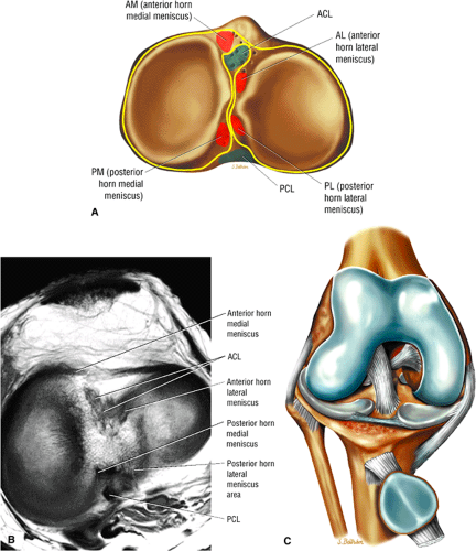 FIGURE 4.182 ● (A) Tibial insertion sites for the anterior cruciate ligament (ACL) and posterior cruciate ligament (PCL). Insertions are also indicated for the meniscal fibrocartilage. The ACL inserts between the anterior attachments of the menisci. The PCL attaches to the posterior intercondylar area and posterior tibial surface. (B) Corresponding axial MR image demonstrating hypointense cruciate ligament insertions. (C) Anterior tibial insertion sites of the ACL and menisci on anterior coronal perspective. |
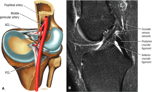 FIGURE 4.183 ● (A) The vascular supply to the cruciate ligaments via the middle geniculate (genicular) arterial branch of the anterior popliteal artery. There is no blood supply derived from the ACL ligament to the bone insertion site. (B) Return venous network for the cruciate ligaments corresponding to the ligamentous arterial anastomosis (sagittal FS PD FSE image). |
With varus or valgus stress, the ACL is injured after collateral ligament failure. Forced valgus in external rotation is the most common mechanism of injury and causes disruption of the MCL and medial supporting structures.20,155,


Related posts:

Stay updated, free articles. Join our Telegram channel
Full access? Get Clinical Tree
