CHAPTER 23 Spinal Injections
INTRODUCTION
The thought process underpinning the use of these injections for specific diagnosis is discussed in other chapters. It should be emphasized that a general principle invoked is that injections are performed for specific diagnoses and that proper testing is performed prior to an injection procedure. This insures that the minimum number of invasive procedures is performed. This chapter focuses on technique and not rationale. Contraindications to the performance of spinal injections include systemic infection, local infection at the injection site, bleeding dyscrasia, and anticoagulation. A detailed analysis of the variety of complications that can result from each of the described spinal injections is covered in Chapter 20 by Botwin. Spinal injections are performed under fluoroscopic guidance to improve accuracy, efficacy, and safety. The interventionalist must be cognizant to limit radiation exposure to the patient, staff, and interventionalist to a minimum. The reader is directed to the radiation safety chapter by Windsor. Local anesthesia is recommended prior to performing the spinal injection procedures discussed in this chapter. Unless there are known ‘caine’ allergies, local anesthesia is done with 1% Xylocaine injecting through a 25-gauge needle creating a skin wheal. The skin wheal can be quite small as it needs to only be greater than the diameter of the needle. Larger skin wheals provide more flexibility for selection of needle placement. The disadvantage of a larger skin wheal is that the skin wheal can be painful to the patient. The acidity of Xylocaine injection can cause a painful burning sensation. Because of this, the Xylocaine can be mixed with sodium bicarbonate to neutralize the acidity and make the injection more comfortable. A 10:1 mixture of 1% Xylocaine and 8.4% bicarbonate is used. The decision to use 1% Xylocaine or the Xylocaine–bicarbonate mixture is under the discretion of the interventionalist. For very experienced spine interventionalists local anesthesia may not be required. Some patients may prefer moderate sedation to better tolerate the procedure. This includes those patients who are anxious, needle-phobic, have lower pain thresholds or are at increased risk of a vasovagal reaction. Additionally, some patients in severe pain may have difficulty getting into the proper position on the fluoroscopy table and may benefit from moderate sedation. In particular, those with severe radicular pain, particularly in the presence of a foraminal disc protrusion or foraminal stenosis may experience severe pain with injection of medication around the involved spinal nerve. However, the level of moderate sedation should be limited. The patient still needs to be awake to appropriately respond to painful stimuli, and should have the ability to communicate with the interventionalist. If nerve is contacted, the patient requires the ability to verbalize that extremity pain is perceived to avoid nerve injury. If the patient is too sedated, the nerve or spinal cord could be penetrated with the patient and interventionalist unaware, resulting in neurologic injury. It is preferable to avoid moderate sedation for diagnostic injections, but this is not always feasible. The intravenous anxiolytic or opiate medication may influence the results, increasing the risk of a false-positive diagnostic injection. One way to mitigate that scenario is to ask the patient to complete the pain drawing and VAS scale after sedation is provided.
NEEDLE TECHNIQUES
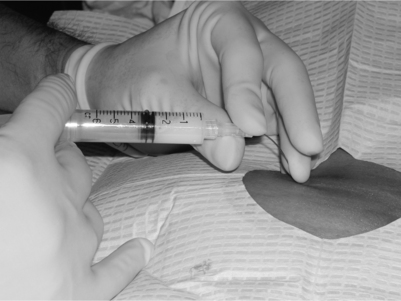
The standard spinal needle has an angled opening of the needle referred to as the bevel. The hub of the needle has a ‘notch.’ The notch and bevel are on the same side in a standard spinal needle. As a needle is advanced through tissue it tends to move towards the sharper side and away from the bevel and notch. The interventionalist, however, does not see the needle tip and bevel, which are already in the patient’s soft tissues. Instead, one typically sees the part of the needle protruding from the skin, the hub portion and notch. Therefore, the interventionalist must be cognizant of the orientation of the notch as the needle is advanced, since the needle tip will tend to move 180 degrees away from the notched side as it is advanced. Novice interventionalists ignore this tendency and often end up trying to fight the needle’s trajectory, while advanced interventionalists learn to use this ‘bevel control’ to their advantage and, instead, drive the needle. Bevel control can be even more accentuated by placing a 10–20 degree bend on the needle tip away from the notched and bevel side as close to the needle tip as possible. We recommend using a sterile gauze when placing the bend to prevent inadvertent contamination of the needle tip. Another technique to enhance control of the needle is to use a concave arc on the needle for even more precision and steerability. The arc is created by holding the needle between the thumb and index fingers while using one of the other digits closer to the skin surface to create the concavity on the same side the needle is being directed toward (Fig. 23.1). This concavity tends to further slide the needle into position. The combination of bevel control and a concave arc directing the needle are effectively like having ‘power steering’ to direct the needle tip wherever it is needed. However, like power steering, the needle will be much more sensitive and less forgiving if these techniques are not understood. Thinner needles (i.e. 25 or 27 gauge) are much more responsive to these techniques than the thicker (18 gauge) needles which tend to respond more to ‘brute force.’ Twenty-two-gauge needles tend to be intermediate in response to these techniques and brute force.
FLUOROSCOPIC VIEWS
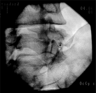
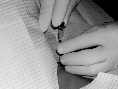
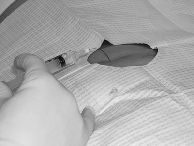
All physicians practicing fluoroscopically guided procedures understand that at least two views are needed to confirm needle tip position. Biplanar imaging, such as anteroposterior (AP) and lateral, are typically utilized. Additionally, other views may be utilized to increase precision, safety, and efficiency in interventional spine care. Therefore, throughout this section, we will describe additional terminology regarding fluoroscopic imaging for each spinal procedure: Trajectory view, Safety view, and the two final-position views. These views are obtained by appropriately positioning the fluoroscope and/or patient. Each procedure is done by using a trajectory view for original needle entry, the Safety View during needle advancement to avoid relevant structure, and two final views to confirm needle position prior to contrast and subsequent medication injection. Trajectory view (aka hubogram, needle view) is the initial one which visualizes the path or route the needle will travel to get to the ultimate target. The image is obtained on the fluoroscope, and this determines the initial skin entry position. When utilizing an unencumbered trajectory view during needle advancement, the target can be efficiently approached without encountering obstructions. As well, radiation and procedure time can be minimized by making sure the needle is positioned parallel to the fluoroscopic beam prior to taking additional fluoroscopic pictures. This is accomplished by advancing the needle along the trajectory established by the fluoroscope’s image intensifier relative to the patient. As the needle is advanced down the fluoroscope’s beam a ‘dot’ rather than a ‘line’ is noted on the image (Fig. 23.2). As the needle tip is advanced close to the desired target, biplanar imaging is utilized. However, to safely advance the needle and avoid penetrating ‘dangerous’ structures, we recommend using the ‘Safety (aka danger)’ view during needle advancement. The ‘Safety’ view is used to ensure that the needle does go where it is supposed to and, more importantly, does not go where it should not be. Careful interventionalists are cognizant of the structures to avoid such as thecal sac, spinal cord, major vessels, lung, and kidney. The safety view is that which best visualizes where these structures are known to lie. Unfortunately, fluoroscopy does not enable visualization of the soft tissue structures to be avoided. However, understanding the correlation of fluoroscopic with three-dimensional anatomy enables safe advancement of the needle using identifiable landmarks. Once the needle tip is believed to be at the desired target, we recommend confirming location with biplanar imaging, or two views prior to confirming with contrast injection. For the experienced interventionalist, biplanar imaging at this stage may not be required. Subsequent to this confirmation, contrast is injected. Once the ideal position and contrast flow is confirmed, the injectate is administered. When advancing spinal needles, the needle should be advanced parallel to the X-ray beam towards the target using the trajectory view. The needle tip and hub of the needle will be superimposed, resembling a target when viewed on the monitor (see Fig. 23.2). When advancing the needle, the hand holding the needle should be braced against the patient. This keeps the needle from advancing with inadvertent patient movement. In the cervical spine or with other delicate procedures, a two-handed technique is often utilized. The ulnar palm of the hand is placed against the patient with thumb and index finger on the sides of the hub to maintain correct orientation of the needle. Such positioning guards against advancing the needle too deep, especially if the patient moves. The second hand advances the needle in small increments in the desired direction (Fig. 23.3). The needle is advanced under intermittent fluoroscopic guidance, checking the direction and advancement of the needle. A metal surgical sponge stick can be used in some injections under continuous fluoroscopic guidance. This is an advanced technique and not recommended in the cervical spine or for novice interventionalists. Total fluoroscopy time with continuous fluoroscopy should not exceed that for the same procedure utilizing intermittent fluoroscopy. If it does, the interventionalist should do the procedure with intermittent fluoroscopy. Additionally, the interventionalist must be careful not to expose his/her hand to the X-ray beam. When viewing the monitor, the interventionalist’s hand should not be present on the images. Partitions on the c-arm can be adjusted to cone down the view and decrease radiation exposure to both the patient and interventionalist. Extension tubing between the needle and syringe limits radiation exposure to the interventionalist’s hands. As well, the using of tubing prevents inadvertent movement of the needle tip during the exchange of syringes and while any agent is being injected. As of 2003, the standard of care for injections that involve the epidural space and/or nerve root dictates that extension tubing be utilized.1 Usually, when performing spinal injection procedures, the needle is advanced to abut upon bone or periosteum next to the target for injection. While some advocate that ‘bone is the interventionalist’s friend,’ others argue that teaching a novice to advance until contact with periosteum may lead to false security while advancing the needle too far. Most of the techniques utilize an approach that traverses skin, subcutaneous tissue, muscle, and then bone. The various approaches try to provide the safest path to the desired target. Bone is often utilized to gauge needle depth and avoid dangerous advancement into deeper structures such as subarachnoid space, spinal cord, spinal nerve, vertebral artery, and/or peritoneum. Once periosteum is reached, the needle is usually carefully redirected only a few millimeters in the desired location utilizing biplanar imaging. A thorough understanding of three-dimensional anatomy and the associated structures is required. The needle is advanced in the ‘Safety’ view which demonstrates structures that must be avoided. Non-ionic contrast is utilized to confirm proper spinal needle placement. Contrast may also demonstrate inadvertent intravascular placement, thereby minimizing potential complications due to vascular injection of medications and will increase the probability of an effective injection. The non-ionic contrast agents typically utilized for spinal procedures are Omnipaque or Isovue, both approved for intrathecal usage. When injecting contrast or medication, it is important not to move the needle tip. As previously mentioned, extension tubing is frequently used for this purpose and is required for epidural space and or nerve root injections. With longer spinal needles in the thoracic and lumbar spine, the needle may be bent while injecting. This keeps the force of depressing the plunger from inadvertently advancing the needle (Fig. 23.4). Of course, since extension tubing is used this potential problem should not be an issue. It should be understood that for intra-articular injection, the therapeutic agent must be injected by connecting the syringe to the hub or the joint space will be rapidly and unnecessarily filled with extra contrast (the contrast that filled the extension tubing). Real-time imaging must be employed regardless of whether extension tubing is used or not. When real-time imaging is used to confirm accurate placement, it inherently means the needle has come to a stop. Then contrast is injected. Simultaneous advancement of the needle and contrast injecting while using continuous fluoroscopy is not appropriate. Unless real-time imaging is performed, vascular uptake may be missed. This means that relying on static fluoroscopy performed after the injection of contrast is insufficient. Aspiration looking for vascular flash-back has a sensitivity of only 46% in the cervical spine2 and 45% in the lumbosacral spine.3 In caudal injections, negative vascular flash-back occurred in only 9.2% of venously placed injections.4 For transforaminal lumbosacral epidural injections, the overall rate of vascular placement was 11.2%.3 At the level of S1, the rate was as high as 21% and in the lumbar level 8.1%. Not only do misplaced needle tips result in suboptimal treatment, but inadvertent intravascular injections can lead to serious complications to include cardiovascular collapse requiring resuscitation,1 spinal cord infarction and cerebral vascular thrombosis.19,20 For these reasons, we reiterate our recommendation that real-time injection of a non-iodinated contrast agent such as Isovue or Omnipaque (and in rare cases gadolinium) be utilized. Some advocate using digital subtraction to even further confirm a nonvascular injection.
DIAGNOSTIC PROCEDURES
When correct needle placement is confirmed by the injection of contrast, medication can then be instilled. Injections may be of two types: diagnostic or therapeutic. With diagnostic injections, local anesthetics without preservatives are used. The agents most frequently used are 1–2% Xylocaine and 0.25–0.5% bupivacaine. A double-block paradigm has been described to reduce false-positive injections.5–7 With the comparative block paradigm, anesthetics of two different half-lifes are utilized. Typically, Xylocaine or bupivacaine is used. The patient is blinded to the medication utilized. Another method to reduce false positives is the use of placebo–control blocks. For that type of double-block paradigm local anesthetic is injected on one occasion and normal saline during another. Ideally, the patient and the interventionalist are blinded to the agent used. With either a comparative or placebo–control injection, the patient is instructed post injection to perform maneuvers that would typically aggravate pain. At The Penn Spine Center we usually require at least an 80% decrement in pain from pre- to post-injection for the diagnostic injection to be considered positive. Others use 50% as the target decrement. Following the injection, the patient is instructed to keep a prospective pain dairy. Since we have found that many patients forget their pain diaries on follow-up, we recommend recording pain response every 15 minutes for 2 hours post procedure, keeping the patient for at least 1 hour and copying their pain diary before they leave. After the first 2 hours, the patient records on an hourly basis the maximum percentage of relief and severity of pain on visual numeric scale until pain returns to less than 50% relief. The patient then returns on a separate day for repeat injection with the other anesthetic. Prior to injection, the patient’s pain dairy is reviewed and the duration of relief and maximum percentage of relief is recorded. If the patient once again has at least 80% relief with the other anesthetic, the patient is instructed in keeping a pain dairy. At follow-up, the patient’s pain dairy is reviewed. The appropriate response is longer relief with bupivacaine over Xylocaine. If this occurs, the patient passes the double-block paradigm and pain is attributed to the structure injected. The patient is then a candidate for various therapeutic interventions related to the structure, as clinically indicated. If the patient has longer relief with the shorter-acting agent or less than the targeted percentage of relief for the procedure to be deemed positive with the second injection, the initial injection was a false positive. In that case, the patient is not a candidate for therapeutic intervention. Most studies utilizing the double-block paradigm have not used a strict criteria regarding the degree of pain relief to be determined a positive block. Studies of the zygapophyseal joint utilized definite relief as positive for the initial injection and 50% relief with the second injection.5,7 Use of 80% relief with the second injection probably increases the specificity by eliminating patients with 50–79% relief. However, sensitivity is lowered and potential positive responders are lost.
THERAPEUTIC PROCEDURES
Additional recommendations
We recommend that procedures are done in a fluoroscopy suite with personnel trained in advanced cardiac life support nearby. As a minimum, continuous monitoring of blood pressure heart rate should be done every 1–5 minutes. If moderate sedation is administered, oxygen saturation, pulse, blood pressure, and level of sedation should be monitored.8–10 In those with hypertension or cardiac pathology, continuous electrocardiogram monitoring should be included.8 Airway and ventilator support should be available in case of respiratory depression. After the procedure, the patient should be taken to recovery and monitored for at least 20–30 minutes for any adverse reaction. Prior to discharge, patients should be alert and able to ambulate independently. We recommend a pain assessment be done prior to discharge. A driver should be present to take the patient home.
Considerations for specific procedures
Anatomic considerations in epidural injections
The epidural space is a triangular space extending from the foramen magnum to the sacral hiatus. The inner border of the epidural space is the thecal sac with the outer meningeal layer of the thecal sac, the dura mater. The dura extends from the foramen magnum to the level of S2. The outer border of the epidural space is the bony spinal canal with its covering periosteum. The anterior border is the posterior longitudinal ligament. The posterior border is composed of the lamina and ligamentum flavum. The lateral border is the pedicle and intervertebral foramina. The epidural space contains loose areolar tissue, a venous plexus, spinal nerve roots, radicular arteries, superficial and deep cervical arteries, arachnoid granules, and lymphatics. A cryomicrotome study of the epidural space found the epidural space to be widest at the midlumbar level with progressive narrowing at more cephalad levels.11 Above C7–T1 no posterior epidural space was evident.11 The width of the epidural space is 1–1.5 mm at C5, 2.5–3 mm at T6, and 5–6 mm at L2.12 In the cervical and thoracic region, the ligamentum flavum in about half of specimens did not fuse in the midline.11 In the cervical spine, the interspinous ligament was absent.11 Absence of the interspinous ligament and midline fusion of the ligamentum flavum have clinical significance when utilizing the loss of resistance technique with a midline interlaminar epidural injection. The lack of resistance from these ligaments could lead to inadvertent entry into the epidural space or dura unbeknownst to the interventionalist. In the lumbar and lower thoracic region exists the dorsomedian dural fold (plica mediana dorsalis).13 The dorsomedian dural fold divides the epidural space into three compartments: ventral and two dorsolateral compartments. The dorsomedian fold also affects the width of the space dorsally, which may be as little as 2 mm or less.13 The presence of the dorsomedian fold can affect epidural injections. The smaller width may predispose to dural puncture with a midline interlaminar approach.13 Additionally, the separate compartments can lead to incomplete flow of medication. Within the thecal sac the spinal cord is present until approximately L2. Rootlets arise from the cord to form the ventral and dorsal nerve roots and pass inferiorly. These roots exit the thecal sac with the dura forming the root sleeve. The dura ends at the proximal margin of the DRG. The dorsal and ventral roots then coalesce to form the spinal nerve as it exits the neural foramen. The dura extends as the epineurium of the spinal nerve. Fibrous tissue of the anterior and posterior epidural space extends as the epiradicular sheath. The epiradicular sheath encloses the dorsal root ganglion and spinal nerve. The epiradicular sheath is the target for a diagnostic selective spinal nerve root injection as it exits the foramen. The foramen is formed superiorly and inferiorly by the pedicle of the superior and inferior vertebrae, respectively. The superior articular process of the zygapophyseal joint forms the posterior wall. The inferior vertebral endplate and disc form the anterior wall. The foramen consists of entrance, mid, and exit zones. The mid-zone of the foramen contains the DRG, ventral root, sinuvertebral nerve, and vascular interconnections. Approaching the exit zone, the ventral root and DRG coalesce to form the spinal nerve. In general, the relation of the DRG to the pedicle is immediately inferior in 90%, medial 2%, and inferolateral in 8%.14 However, in the lumbar spine the location of the DRG may vary dependent upon the level of the lumbar spine.15 Hamanaishi and Tanaka,15 studying the location of 442 DRGs in 104 MRI scans reported: (1) extraforaminal location in 100% at L2, 48% L3, 27% L4, and 12% L5; (2) intraforaminal location in 52% L3, 72% L4, and 75% L5; and (3) intraspinal location 13% L5 and 65% S1. In the cervical spine, the spinal nerve exits in the inferior aspect of the foramen with vascular structures in the superior aspect of the foramen. The spinal nerve is posterior to the vertebral artery.16 In the lumbar spine, the spinal nerve and vessels are in the superior aspect of the foramen. The spinal nerve upon exiting the foramen travels inferior, lateral, and anterior. The spinal cord receives blood supply to the posterior third via the two posterior spinal arteries. The posterior spinal arteries arise from the posterior inferior cerebellar arteries. The posterior spinal arteries consist of plexiform channels and run along the line of attachment of the dorsal roots of the spinal nerves.17 The arteries also receive supply from the posterior radicular arteries. The anterior spinal artery arises from the vertebral artery and is only sufficient for the upper cervical region.17 The vertebral artery arises from the subclavian and enters the costotransverse foramen at C6 and exits at C1 and crosses posteriorly behind the arch of C1 before entering the skull through the foramen magnum. Branches from the vertebral artery descend and form a single artery, the anterior spinal artery. The anterior spinal artery receives added supply at different intervals throughout the spine. The anterior spinal artery is divided into cervical, thoracic, and lumbar segments.18 Spinal arteries arising from the vertebral, subclavian, intercostals, aortic, and iliac arteries enter through the intervertebral foramen and divide into the anterior and posterior radicular arteries.17 The majority of the radicular arteries supply primarily the nerve root. A variable number of anterior radicular arteries help supply the anterior spinal artery. These feeder arteries are larger arteries and have been termed radiculomedullary arteries.19 These arteries may ascend and descend within the thecal sac to supply the anterior spinal artery. A variable number of these feeder arteries are present in the cervical region but at least one or two are typically present, usually entering at the level of C5–6.20 Below T8 the major supply of the anterior spinal artery is through the artery of Adamkiewicz.19 Interruption of this artery can result in cord infarction of the anterior two-thirds, the anterior spinal artery syndrome. The artery of Adamkiewicz arises as a branch from the aorta and enters from the left side at T9–L2 in 85% but can enter as low as S1.21,22 A right-sided radiculomedullary artery in the lumbar region can contribute to the anterior spinal artery. Injury to a radiculomedullary artery compromises circulation to the cord with the risk of ischemia or infarction. Drainage of blood from the cord occurs through the anterior and posterior spinal veins. These veins drain into radicular veins which in turn drain into the epidural venous plexus. The plexus exits the intervertebral foramen and enters into the external venous plexus. Blood then drains into the vertebral, intercostals and lumbar veins.17
TYPES OF EPIDURAL INJECTIONS
Injections into the epidural space are of three general types: caudal, interlaminar, and transforaminal. Although interlaminar and caudal injections may be performed with or without fluoroscopic guidance (we advocate the former as routine), transforaminal injections require fluoroscopic guidance. Interlaminar or caudal epidural injections done without fluoroscopic guidance are also termed blind epidural injections. Techniques of hanging drop and loss of resistance are utilized to identify entry into the epidural space. The accuracy of blind epidurals has been tested. The loss of resistance technique in the cervical spine for blinded interlaminar injections has a miss rate of 53%.23 In the lumbar spine the miss rate ranges from 17% to 30%.24,25 Caudal epidural injections have a miss rate of 25–52%.4,25 However, if the sacral cornu are easily palpated and there is no palpation of subcutaneous air, loss of resistance blinded injection with an experienced interventionalist may be successfully performed in 91.3%.26 If the landmarks are not easily the palpated, the success rate in the same study was 54.5%. Landmarks were readily palpable in only 59.3% of subjects.27 Under fluoroscopic guidance, El-Khoury27 had a failure rate of 2.5% for caudal injections. Of two failures, one was secondary to dural puncture and the other was from inability to place the needle in a subject who had suffered a sacral fracture. Anatomic variance of the sacral hiatus in 15% may prevent successful caudal injection.28 Variations included a hiatus of less than 8 mm in length, severe partial agenesis, complete agenesis, absent hiatus, bony septum in canal, and angulation of the sacrum.29 The rate of misplacement of blind epidural injections is unacceptable, especially considering the routine availability of fluoroscopy. For additional safety, digital subtraction should be considered, if available, when performing transforaminal injections with precarious vascular anatomy such as in the cervical spine or high lumbar locations (L1–3, artery of Adamkiewicz watershed zone). Other safety measures include using a local anesthetic test dose and routine remixing of the glucocorticoid if it is of the type that tends to accrete. Transforaminal injections have theoretic advantages over interlaminar injections. Interlaminar injections place medication in the posterior epidural space. Stojonavic et al.23 demonstrated that cervical interlaminar injections contrast entered the ventral epidural space in only 28% and remained unilateral in 51% of injections. In the thoracic spine, contrast entered the ventral epidural space in only 24% injections.29 Kraemer et al.30 demonstrated medication flowed dorsally with interlaminar epidural injections. In a randomized, controlled trial, perineural injection was found to be superior to interlaminar epidural injection in radiculitis from herniated lumbar disc,30 supporting the benefits of target-specific injection. With therapeutic selective nerve injections, medication is delivered directly to the targeted spinal nerve, dorsal root ganglion, and nerve root. This is particularly important where resistance to fluid flow occurs such as in spinal stenosis, foraminal disc protrusions, and epidural fibrosis. In cases of axial pain felt to be discogenic in origin, transforaminal injections place the medication ventrally in the epidural space adjacent to the posterior anulus, posterior longitudinal ligament, and sinuvertebral nerve.
Diagnostic selective spinal nerve root injections target the spinal nerve, nerve root, and DRG only. A small aliquot of local anesthetic is injected to anesthetize the spinal nerve to determine if pain is emanating from the specific spinal nerve and nerve root. Diagnostic selective spinal nerve root injections are indicated when the etiology of pain radiating into an extremity is in question. A pre- and postinjection pain drawing and visual analogue scale is obtained. Post procedure, the patient should perform activities which usually provoke the pain. If the patient has an 80% decrement in pain, the diagnostic injection is considered positive.31
General techniques
Non-ionic contrast is utilized to confirm proper needle placement. Contrast should outline the epidural space and/or the spinal nerve depending on the type of injection performed. The contrast will display either a negative or positive outline of the epidural space or the nerve (Fig. 23.5). Injection into the epiradicular sheath usually is of low resistance and not painful. However, the injections may be painful when there is severe nerve irritation and/or compression, such as with a foraminal disc herniation. In these situations, inject medication slowly, approximately 1 second per 0.25 cc per second, to minimize pain. Also, slower injection may reduce the incidence of postinjection headache. If pain develops during the injection, stop injecting until the discomfort dissipates. Then resume injecting, but slowly to avoid pain. If significant resistance is encountered, do not force the medication. Recheck the needle placement with real-time fluoroscopy to insure proper placement and that the needle tip has not been advanced intraneurally. With intraneural needle placement and injection of contrast, the patient typically experiences severe radicular pain. When severe radicular pain is described by the patient the injection should be stopped immediately. The contrast will usually demonstrate a sharp line within the substance of the nerve. The needle should be withdrawn back into the epiradicular sheath and rechecked with real-time fluoroscopy. The other contrast pattern that is important to recognize is a subarachnoid pattern. This pattern will give a myelographic outline. If this occurs, the procedure is abandoned as subarachnoid instillation of medication can be catastrophic. There is the risk of respiratory depression, hypotension, syncope, and arachnoiditis.32–36 Transforaminal injections can be performed by CT scan with advantages of less radiation to the interventionalist along with visualization of nerve and soft tissue structures.37 However, CT has disadvantages of greater expense, being less rapid to perform, and there being no ability to perform real-time injection of contrast.37 The latter is a major disadvantage as inadvertent radiculomedullary injection can result in paralysis.19,20 Fluoroscopic guidance with real-time injection of contrast is recommended.
Caudal epidural injection
The caudal epidural space extends between the sacral hiatus and the caudal end of dura which terminates anywhere between S1 and S3, but usually at the inferior border of S2 segment. The contents of the canal include sacral nerves, fatty tissue, and sacral venous plexus, the latter usually terminating at S4 segment but may continue inferiorly in some patients. The canal size is variable, with documented volumes from 15 to 60 ml. Variations in sacral anatomy have been mentioned by several authors. These variations include, but are not limited to absence of sacral hiatus (prevalence in general population is reported to be about 8%), location of the sacral hiatus, curvature and location of sacral foramina, bifid sacrum and sacral canal stenosis secondary to previous sacral fracture. The radiological landmark of the sacral canal is a translucent layer posterior to the sacral segments in lateral views with the sacral hiatus visible as a translucent opening at the base of the caudal canal. After consenting, the patient is placed prone on the fluoroscopic table with a pillow under the abdomen and legs abducted. For the right-handed interventionalist, it is usually recommended to stand on the left side of the patient. In nonobese patients, the sacral cornua can actually be palpated, which provide landmark to locate the hiatus. The skin of the region is then prepped with povidone-iodine and draped with a fenestrated sterile drape. A 3 inch, 22-gauge needle is usually selected for the procedure. The entry point of the skin is approximately 2 cm distal to the sacral hiatus. The needle is advanced at about 45 degrees until it reaches the sacrococcygeal ligament. The needle is then slightly withdrawn, and the hub made to lie parallel to the skin surface, before advancing the needle through the sacral hiatus into the sacral canal. The needle is advanced to the interval between the sacral foramina of S2 and S3. Any further advancement of the needle could result in advertent dural puncture. The position of the needle is verified on lateral fluoroscopic views to avoid the incorrect placement because of anatomical variations. The use of contrast material is highly recommended to confirm the absence of venous run off, as the needle might be in the sacral venous plexus without actually causing a flash back. The most common contrast spread pattern is a ‘Christmas tree’ shape. Typically, 1.0–3.0 mL of contrast material will demonstrate appropriate position. After aspiration for blood and CSF is negative and venous run-off ruled out by contrast fluoroscopy, 2–3 mL of methylprednisolone along with 10 mL of lidocaine is instilled. This provides enough volume for the injectate to reach the level of L3 vertebral body.
Interlaminar epidural injection
Cervical
With progressive cephalad narrowing of the epidural space, the width at C5 has been shown to be 1–1.5 mm12 with no evident posterior epidural space above C7–T1. It has also been shown11 that in 50% of the specimens ligamentum flavum did not fuse in the midline, and the interspinous ligament was absent. With these anatomic considerations, the most common injection site for cervical interlaminar injection is the C7–T1 or C6–7 interspace. Because of the relatively small size of the cervical epidural space, a catheter technique is recommended, particularly in an elderly population. Feeding a catheter from the upper thoracic, preferably T1–2, epidural space to the desired segmental level in the cervical spine significantly reduces the chance of cervical cord damage. The recommended positions for the cervical interlaminar injections include sitting, lateral, and prone. The sitting position is easiest for the patient and enhances operator’s ability to flex the cervical spine and identify the midline. However, its use is limited practically in patients prone to vasovagal syncope and those who are unable to assume a sitting position because of underlying vertebral compression fractures. In these situations, a lateral position is recommended, particularly when tunneled epidural catheters or implantable devices are considered. This position may, however, pose technical difficulty because of spine rotation. The most commonly used position is the prone position. One must, however, ensure flexion of the cervical spine to widen the epidural space. After optimal position and skin prep with povidone-iodine, the appropriate landmarks are identified. A midline approach is selected. The midline of the desirable interspace is identified by palpating the spinous processes above and below the space, with a lateral rocking motion of these processes. Usually 3 inch or 1½ inch, 22-gauge needle is selected, and advanced in the midline. Cervical epidural injections have been performed blind without fluoroscopic guidance. However, anatomic studies have found high rates of discontinuity in the ligamentum flavum in the cervical region and a smaller epidural space than lumbar levels. This variability can potentially result in higher rate of dural puncture and unsuspected spinal cord injections during blinded injections. Fluoroscopy and contrast administration are, therefore, highly recommended to obviate these complications. If a blind technique is used, the epidural space is identified by the loss of resistance technique without ballottement. The hanging drop method is not used because of the associated 2.0% failure rate, compared with less than 0.5% failure rate for the loss of resistance technique. After satisfactory needle position is confirmed and gentle aspiration negative for both blood and the CSF, medications are injected. Because of the relatively small size of the cervical epidural space, a catheter technique is recommended, particularly in an elderly population. Feeding a catheter from the upper thoracic, preferably T1–2, epidural space to the desired segmental level in the cervical spine significantly reduces the chance of cervical cord damage.
Transforaminal epidural injection
Cervical
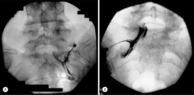
Anterior, lateral, posterior and oblique approaches have been utilized for cervical transforaminal epidural injections. The anterior approach has been described by many practitioners.16,38–40 The main disadvantage of this technique is the vertebral artery is at risk of puncture since it is located anterior to the spinal nerve. When placing the needle into the foramen, the posterior wall of the foramen is targeted to avoid vertebral artery puncture.37 Also, the interventionalist has to use their fingers to push the trachea and esophagus to one side and the carotid artery to the other. These structures are also at risk for puncture. With a left-sided approach, the thoracic duct could also be inadvertently punctured. These problems led Vallee et al.41 to propose a sitting, lateral approach. With the lateral technique, the patient is placed in a sitting position to help lower the shoulder.41 The lateral approach targeted the superior articular process to gauge depth and to avoid the more anteriorly located vertebral artery. The c-arm is then aligned obliquely to advance the needle medially and ventrally into the foramen under fluoroscopy. Position is then checked in the anterior plane. The main disadvantage of placing the patient in a sitting position would be in the event a vasovagal reaction or in a patient requiring moderate sedation. A posterior approach has been described.16 The patient is placed in the lateral decubitus position. The needle is entered 5–7 cm from midline and directed at 45–60 degree angle until it touches the transverse process.16 The needle is then advanced to touch the nerve root extraforaminally. An oblique approach with the patient lying supine has the advantages of the lateral technique without its disadvantages. With this technique the needle can be placed into any portion of the foramen instead of being relegated to an extraforaminal location. The oblique approach also keeps the spinal nerve posterior to the vertebral artery, decreasing the risk of puncture compared to an anterior approach. The oblique approach is the recommended technique. Patient and fluoroscopy positioning are critical to allow the procedure to be done safely and easily. The patient is placed in a supine or supine-oblique position. A towel or blanket is placed under the head to place the spine parallel to the fluoroscopy table. A common mistake is to allow the patient to shrug the shoulder (Fig. 23.6A). The shoulder should be depressed to keep it from interfering with viewing the spine under fluoroscopy (Fig. 23.6B). The patient or c-arm is then rotated to place the foramen perpendicular to the radiographic imager. In this position, the superior articular process is well visualized (Fig. 23.6C). Avoid placing the spine too obliquely, which can rotate the vertebral artery into the area of injection (Fig. 23.7). Remember, the vertebral artery runs through the costotransverse foramen from C1 to C6. Once positioned, the patient is prepped and draped in a sterile manner. A skin wheal is raised with a 10:1 mixture of 1% Xylocaine and 8.4% bicarbonate, though some interventionalists do not perform this step. The bicarbonate is used to neutralize the acidic Xylocaine and diminish the burning sensation the patient may feel with the skin wheal. A 22- or 25-gauge 1.5–2.5 inch spinal needle is then inserted perpendicular to the midportion of the superior articular process and advanced until bone is reached. As touching periosteum is painful, one must only gently touch bone. As described above, it is not necessary to contact periosteum. During needle insertion, the ulnar aspect of the hand that is holding the needle should be against the patient. If the patient moves, the hand against the patient keeps the needle from inadvertently being advanced. By utilizing bone to gauge depth, dural puncture and spinal cord puncture can be averted. As well, biplanar imaging and utilizing a ‘safety’ view will also assist in avoiding inadvertent injection into undesired structures. Additionally, by targeting the superior articular process in the oblique position, the vertebral artery, which is anterior, is kept away from the needle. For a therapeutic injection, the needle is directed only slightly caudal and ventral a couple of millimeters into the foramen. Transforaminal injections are completed by passing the needle tip to the anterior half of the foramen. This is accomplished with minimal pain when the needle tip is advanced along a line that bisects the cephalad and caudal portions of the foramen. In this fashion, the existing root is typically missed and unnecessary pain is avoided. A diagnostic selective nerve root injection requires the needle be directed caudally and slightly ventral to touch the spinal nerve just as it exits or where it resides outside of the foramen. Care must be taken not to pierce the spinal nerve and every effort is made to minimize the production of radicular pain during needle placement. If radicular pain is experienced, the needle should be slightly withdrawn. Position is then checked in the oblique and AP planes. In the oblique plane, the needle should just be slightly anterior to the superior articular process but still in the posterior aspect of the foramen. In the AP plane the needle should not be beyond the six o’clock position of the pedicle or there may be risk of dural puncture (Fig. 23.8). The stylus is then removed. A syringe filled with contrast agent is connected to tubing and flushed with contrast. The tubing is then connected to the spinal needle. Under real-time fluoroscopy, contrast is injected to confirm needle placement (Fig. 23.9). Contrast flow should clearly be along the targeted spinal nerve and if desired into the epidural space (medial to the ipsilateral lateral mass) (Fig. 23.10). One must carefully watch for any vascular pattern. If available, digital subtraction is used to confirm a nonvascular injection. If a vascular pattern is noted, the needle needs to be repositioned in the foramen. If there is an arterial pattern, we recommend aborting the injection at that level. When repositioning the needle away from a venous injection, the needle is withdrawn out of the foramen. The tubing is removed and the stylus replaced into the spinal needle. The needle is then repositioned on the superior articular process. The needle is then advanced in a different angle, typically more caudally as radicular vein and artery are in the cranial aspect of the foramen. The position is once again checked in the oblique and AP planes. With correct placement, the tubing with contrast is then reattached and contrast injected to check placement. Contrast should outline the spinal nerve and demonstrate epidural flow without evidence of subarachnoid flow. It is absolutely necessary to use a test dose of about 0.8–1.0 cc of 1–2% lidocaine to confirm that there is no adverse reaction. At 90 seconds post-injection, the patient must be queried regarding experiencing periorbital numbness, a metallic taste, auditory changes, agitation, and difficulty breathing and observed for seizure activity. If no complaints are articulated that would suggest intravascular or subarachnoid placement of the local anesthetic, a quick motor screen must be conducted. The patient is asked to move the fingers and toes. If no paresis is observed, a glucocorticoid with or without local anesthetic may then be injected. We typically utilize 1–2.0 cc of dexamethasone Soluspan and 0.25 cc of 1% Xylocaine. Some interventionalists are now injecting the therapeutic agent under continuous fluoroscopy to ensure there is no intravascular flow. It is believed that this will help prevent radiculomedullary injection with risk of anterior spinal artery syndrome or vertebral artery injection with subsequent cerebral or spinal cord ischemic event. This latter step is unnecessary provided the other safety measures described have been properly performed. For a diagnostic selective spinal nerve root injection, the needle bevel is rotated inferiorly and 0.5 cc of contrast injected. Contrast should outline the spinal nerve root and DRG but should not extend beyond this (Fig. 23.11). Then 0.5 cc of 1% Xylocaine is instilled. Again, continuous fluoroscopy with injection is recommended.
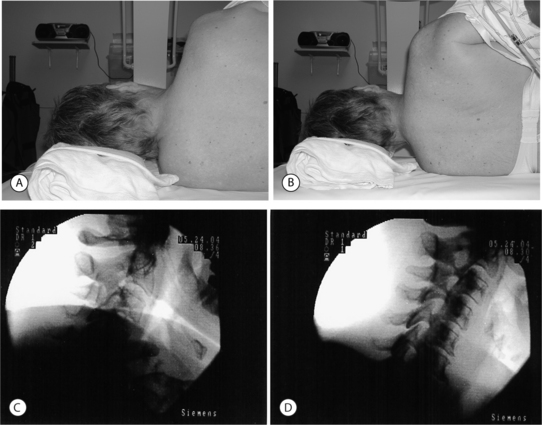
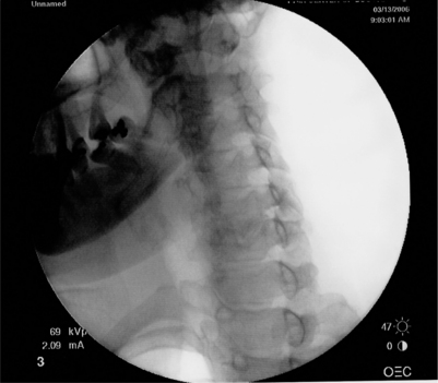
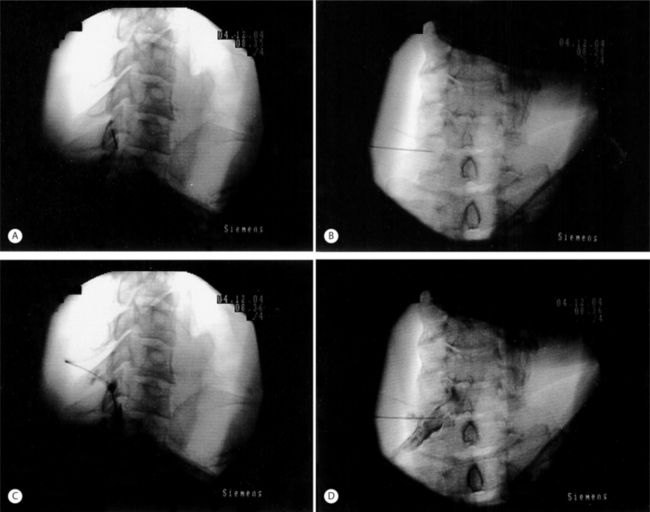
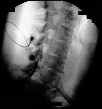
Fig. 23.10 Cervical transforaminal injection. Contrast outlines spinal nerve and demonstrates epidural flow.
Additional safety concerns in cervical transforaminal epidural steroid injections
There have been many recent reports regarding serious adverse outcomes directly related to cervical transforaminal ESIs. Although they are not published, the authors are aware of at least 10 litigation cases involving post-procedural infarction of structures supplied by either the cervical, cerebellar, or cerebral vasculature. These procedures have resulted in long-term cognitive or physical dysfunction and even death. The current consensus theory for the etiology of these catastrophic events is that particulate from the steroid suspension is injected into the cervical arterial vasculature, resulting in subsequent infarction. In an effort to lower the risk:benefit ratio, we reiterate our recommendations. We need to clarify, however, that these recommendations have not been proven to decrease the procedural risk but are based on informal consensus discussions. Nevertheless, the following steps, exclusive of the use of digital subtraction, represent the minimum standard that must be followed to be safe:


Stay updated, free articles. Join our Telegram channel

Full access? Get Clinical Tree


