Fig. 7.1
Low-dose knee CT protocol to reduce radiation dose, only regions relevant to orthopaedic and biomechanical analysis are scanned. Scanning parameters are further optimised to reduce dose yet retain image quality
7.3 Extended Scale for CT Imaging of Metal Implants
A key feature of orthopaedic CT protocols is the “extended scale” feature, which allows the storage of a wider range (−10,240 to +30,710) of Hounsfield Units (HU) than normal scale (−1,024 to +3,071). This has a direct benefit for orthopaedic software, because with extended scale, the range of HU values in metal implants (1,000 to 15,000+) can be fully represented, enabling software to extract high-quality surface information from the implant. This information is critical for precisely measuring implant position and orientation.
A key feature of orthopaedic CT protocols is the “extended scale” feature, which allows the storage of a wider range (−10,240 to +30,710) of Hounsfield Units (HU). With extended scale, the range of HU values in metal implants (1,000 to 15,000+) can be fully represented, enabling software to extract high-quality surface information from the implant.
7.4 Orthopaedic Frames of Reference
The most important role of orthopaedic software is to quickly set up repeatable, reliable frames of reference for analysis and review. The importance of frame of reference is a key difference between standard imaging and orthopaedic imaging, and thus a difference between conventional imaging analysis software and orthopaedic software. Here, we describe how correct frames of reference are crucial for analysis and understanding in orthopaedics. We then describe how orthopaedic software can generate these frames of reference quickly using anatomic information.
Frames of reference are important for orthopaedic analysis because of:
7.4.1 Patient Position in CT Scanner
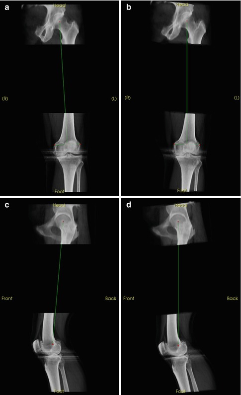
There is always an alignment difference between the patient’s anatomy in the scanner and axis of the scanner (Fig. 7.2). This difference is exacerbated when imaging patients with severe osteoarthritis, who are limited by pain and cannot fully straighten their legs, or imaging patients with fixed flexion deformities. These alignment differences between patient and scanner can be many degrees, which can be a critical error when trying to plan or measure component placement to sufficient accuracy. Similarly, when using the contralateral limb to inform diagnosis or surgical planning, it is important to have a consistent frame of reference between the two limbs.


Fig. 7.2
Views corrected with regard to anatomical frames of reference for patient position in the scanner. (a) Uncorrected AP. (b) True AP. (c) Uncorrected lateral. (d) True lateral
7.4.2 Relate 3D Imaging to Alignment in the OR
The main purpose of orthopaedic 3D imaging is to aid the orthopaedic surgeon, who needs to translate the imaging information to the operating room. In surgery, the surgeon can directly view only a small portion of the bony anatomy. As such, there are only a few landmarks available to orient and plan the surgery. Orienting the 3D images to the same landmarks and frames of reference that the surgeon uses during surgery is critical to maximising the benefit of pre-operative imaging.
7.4.3 Biomechanics
Joint reconstruction attempts to optimise the loading patterns on a patient’s joint for everyday activities such as walking, sitting and climbing stairs. These activities take place in a standing or gravity-oriented reference frame. 3D imaging, however, takes place with the patient lying down, not under the load of gravity. Biomechanical frames of reference can overcome some of this limitation, by reorienting the bones to the standard biomechanical loading paths. Planning of a joint replacement can then be done from a biomechanical basis.
7.4.4 Allow Accurate 3D Analysis Over Time
Relating two scans, such as pre- and post-operation, or follow-up over time, are important parts of orthopaedic diagnosis. Consistent frames of reference allow direct comparison of a series of images.
7.4.5 Allow Accurate 3D Analysis Between Modalities
For serious cases, patients often receive 3D scans from different modalities (e.g. MRI and CT). Consistent frames of reference allow direct comparison of the two images without the confounding factor of misalignment.
7.4.6 Allow Comparison of 3D Images Between Patients
For orthopaedic studies, it is important to be able to relate observations (such as anatomic measurements) and results (such as achieved implant orientation) across patients. Appropriate frames of reference will allow this comparison.
Orthopaedic frames of reference are important for orthopaedic image analysis because of:
Variable patient position in the CT scanner
Need to relate 3D imaging to alignment in the OR
Need to establish biomechanically relevant information
Need of accurate measurements over time, between modalities and patients
7.5 Anatomical Frames of Reference
The optimal way of setting up a repeatable frame of reference is to use anatomical landmarks. Orthopaedic software should (1) make the selection of these anatomical landmarks quick and (2) calculate the resulting frames of reference automatically. Here we provide a precise description of knee anatomical landmarks used for determining frames of reference, a precise explanation of the mapping between anatomic landmarks for the knee, and the resulting frames of reference. We then show how orthopaedic software [3] can enable rapid selection of these landmarks and the calculation of the corresponding frames of reference.
The choice of what anatomical landmarks to use as indicators of the frame of reference is an ongoing research topic (e.g. [4–6]).
The choice that we provide here is a trade-off between (1) landmarks that best represent biomechanics, (2) landmarks that are also accessible during surgery [7] and (3) landmarks that are present both before and after joint replacement surgery. This last feature is critical when trying to measure the achieved position of an implant placement relative to a pre-operative plan or comparing a reconstructed joint with a native joint.
The presented landmarks and mappings are presented in some mathematical detail. The reason is to allow a common framework that any software package can implement. Further, mathematical language is used to guarantee that the resulting frames of reference have orthogonal bases (all axes are perpendicular to one another).
7.5.1 Conventions
All frames of reference have orthonormal bases, so all calculations involving ±x, ±y and ±z are assumed to be normalised (or require normalisation).
+x is to the left of the patient.
+y is to the back (posterior) of the patient.
+z is to the head of the patient.
+medial is a vector pointing to the middle of the body along the x-axis. Thus, +medial is equal to +x on the right leg and –x on the left leg.
These are similar to the default axis definition used by most CT scanners.
An AP view is with the view direction in the +y direction or the xz plane
An axial slice is an xy plane.
A sagittal slice is an yz plane.
7.5.2 Femur
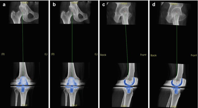
We define the femoral frame of reference as containing the mechanical axis of the femur (passing from the centre of the femoral head to the centre of the knee) and the axis of rotation of the knee, with the origin at the centre of the knee. We use the epicondyles and the femoral head to define the anteroposterior plane, with the midpoint of the transepicondylar line taken as the centre of the knee (Fig. 7.3). Note that there are a number of knee landmarks commonly used for measurements; we have chosen the epicondyles because they remain after total knee replacement (Fig. 7.4).


Fig. 7.3
Rapid selection of anatomic landmarks to set up a “true” AP view of a femur. Simultaneous slice and reconstruction views provide straightforward way of selecting and verifying anatomic landmarks, even in the presence of metal artefact. (a) Femoral head centre. (b) Medial epicondyle. (c) Lateral epicondyle

Fig. 7.4
Alignment to biomechanical frames of reference. If uncorrected, these alignment differences directly limit the accuracy of measurements. (a) Uncorrected AP. (b) True AP. (c) Uncorrected lat. (d) True lateral
Landmarks:
Femoral head centre: Centre of the femoral head
Medial epicondyle: Most medial point on the condyle with respect to the femoral mechanical axis
Lateral epicondyle: Most lateral point on the condyle with respect to the femoral mechanical axis
Mechanical frame of reference:
Origin at the midpoint between medial and lateral epicondyles
+z points from origin to femoral head centre
−y is the normalised cross product of the normalised vector pointing from the rightmost epicondyle to the leftmost epicondyle and +z
+x is the normalised cross product of +y and +z
7.5.3 Tibia
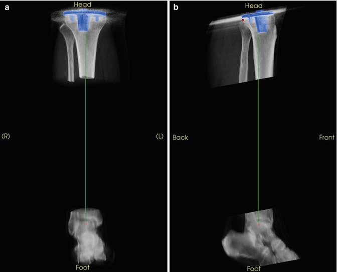
The literature describes several ways of defining frames of reference for the tibia [8–12]. Again, we choose landmarks that exist both before and after a total knee replacement and derive the mechanical frame of reference from those (Figs. 7.5 and 7.6).


Fig. 7.5
Rapid selection of anatomic landmarks to set up a “true” AP view of a tibia. (a) Talus centre. (b) Medial tibial plateau. (c) Lateral tibial plateau

Fig. 7.6
Tibia aligned to the mechanical axis, with an AP defined by the posterior aspect of the tibial plateau. (a) AP of aligned tibia. (b) Lateral of aligned tibia
Landmarks:
Talus centre: Centre of the talus
Proximal tibial centre: Point at the centre of the proximal tibia. If comparing native knees, use a point at the centre of the interspinal sulcus, otherwise, a point at the centre of the tibial plateau distal to the implant.
Medial posterior condyle: Most posterior point with respect to the tibial mechanical axis on the medial condyle. If an implant is present, use the most proximal region on the bone whose margins are sufficiently identifiable through the metal artefact.
Lateral posterior condyle: Most posterior point with respect to the tibial mechanical axis on the lateral condyle. If an implant is present, use the most proximal region on the bone whose margins are sufficiently identifiable through the metal artefact.
Mechanical frame of reference:
Origin at the proximal tibial centre.
+z points from talus centre to proximal tibial centre.
+y is the normalised cross product of +z and the normalised vector pointing from the rightmost posterior condyle point to the leftmost posterior condyle point.
+x is the normalised cross product of +y and +z.
Stay updated, free articles. Join our Telegram channel

Full access? Get Clinical Tree


