Sacropelvic Fixation Techniques
Floreana A. Naef
Khaled M. Kebaish
DEFINITION
Sacropelvic fixation is a term used to describe instrumentation into the sacrum and pelvis.
The most common indication is a long spinal fusion to the sacrum. Other indications include high-grade spondylolisthesis, flat back syndrome requiring corrective osteotomy, and correction of pelvic obliquity.
The purpose is to provide secure distal fixation points that resist the strong flexion moments and cantilever forces present at the lumbosacral junction.
Multiple techniques are used, including the Galveston rod, the iliac screws, and the S2 alar iliac (S2AI) technique.
ANATOMY
A clear understanding of the anatomy of the sacrum and pelvis is crucial to the safe and accurate placement of sacral and pelvic instrumentation. Familiarity with the anatomy of the sacrum, ilium, and sacroiliac (SI) joint is of particular importance.
The Sacrum
The sacrum lies at the junction between the mobile and fixed portions of the spine and functions as a keystone that unites the two hemipelvises.
The sacral vertebrae are fused, and the transverse processes merge into the expanded lateral sacral ala.
The majority of the bone in the sacrum has a cancellous osseous structure.26 The trabecular density is greatest in the pedicle and body of the vertebrae and least in the sacral ala.26 Therefore, sacral pedicle screws are best directed toward the midline.20
The sacrum does not contain a true pedicle, but rather, a confluence of cancellous bone between the sacral body and the ala. Compared to pedicles in the mobile spine, this area is capacious. The S1 pedicle has a mean length of 46.9 ± 3.3 mm in women and 49.7 ± 3.7 mm in men and is angled roughly 40 degrees from the midline (FIG 1).29
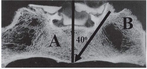 FIG 1 • Cross-section of sacrum. The bone density is greatest in the pedicle and body of the vertebrae (A) and lowest in the ala (B). Arrow marks the location of S1 pedicle. |
The Ilium
The ilium is the most superior of the three bones that make up the os coxa.
In adolescents, the ilium is connected to the pubis and the ischium through the triradiate cartilage. Fusion of this cartilage completes between 13 and 16 years of age in most patients.
In thin patients, the posterior superior iliac spine (PSIS) is marked by an overlying dimple in the skin. A transverse line drawn between these two dimples crosses the sacrum at the level of S2.
The structures of the greater sciatic foramen are at risk of damage during instrumentation of the pelvis.11
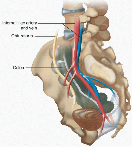 FIG 2 • Important anatomic structures overlying the sacrum. |
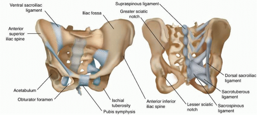 FIG 3 • Ligamentous support and bony anatomy of the pelvis. |
The Sacroiliac Joint
The SI joint is an L-shaped synovial joint with an irregularly contoured surface that interlocks in order to resist movement. The joint functions to transfer axial load from the torso onto the hemipelvises.
The joint is stabilized by the anterior SI ligament, interosseous SI ligament, and the posterior SI ligament (FIG 3).
BIOMECHANICS
Fusions across the lumbosacral junction are a particular challenge for spine surgeons and this location has a high incidence of pseudarthrosis.11
Substantial biomechanical forces are concentrated at the lumbosacral junction. The fusion mass above the sacrum acts as a long lever arm that transmits flexion, extension, and torsional forces from the spine above. These forces cause motion at the junction that may increase the risk of pseudarthrosis.4,7
Furthermore, the density of bone in the sacrum is poor, and obtaining adequate fixation is a particular challenge.10
McCord et al18 introduced the concept of the lumbosacral pivot point (FIG 4), which is defined as the middle of the osteoligamentous column at the junction between L5 and S1.
The farther that the pelvic implant progresses anterior to this point, the more stable the construct. Furthermore, instrumentation that crosses the SI joint is not effective unless it passes anterior to this pivot point.18
 FIG 4 • Lumbosacral pivot point. Lateral (A) and axial (B) views of the pivot point. |
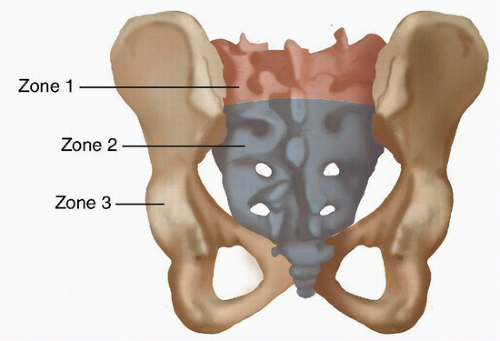 FIG 5 • Zones of pelvic fixation. Biomechanical strength increases as you progress from zone 1 to zone 3. Furthermore, zone 3 allows placement of the instrumentation the farthest anterior to the pivot point. |
IMAGING
Standing full length lateral and posteroanterior (PA) plain radiographs should be obtained in all patients with a spinal deformity, to evaluate overall alignment of the spine.
Due to the complex and variable anatomy of the sacrum, computed tomography (CT) imaging may be helpful for planning of screw placement but is not always necessary.
Identification of anatomic abnormalities such as dural ectasia, Tarlov cyst, or prior harvesting of iliac crest bone that might alter the necessary surgical approach should be completed prior to the surgical procedure.
SURGICAL MANAGEMENT
Indications
Long spinal fusions
The most common indication for sacropelvic fixation is a long spinal fusion to the sacrum.11 The definition of a long spinal fusion is controversial. Most agree that fusions that cross the thoracolumbar junction and progress to the sacrum should be augmented with pelvic anchors. However, we feel that pelvic anchors should also be considered in fusions that extend above L2 and progress to the sacrum.
Conditions that commonly require a long spinal fusion include lumbar scoliosis in adults, children with a structural lumbosacral scoliotic curve, paralytic kyphoscoliosis, paralytic and neuromuscular kyphoscoliosis, and congenital scoliosis.20
High-grade spondylolisthesis
Correction of grade III or higher spondylolisthesis places excessive force on the posterior implants.6
Instrumentation into the pelvis serves as an adjunct to the S1 pedicle screws and may reduce the incidence of pseudarthrosis and distal implant failure.20
Flat back syndrome requiring corrective osteotomy
Flat back syndrome refers to the loss of lumbar lordosis following a posterior spinal fusion.28 Patients present with pain, loss of sagittal balance, and caudal disc degeneration.
Correction of the deformity frequently requires osteotomies and a long fusion to the sacrum.28 These fusions should be supplemented with pelvic instrumentation to decrease the risk of pseudarthrosis.
Correction of pelvic obliquity
Pelvic obliquity is common in patients with neuromuscular deformities.
Correction of the coronal misalignment frequently requires pelvic fixation.9
Other disorders
Less common indications include sacrectomy performed for sacral tumors, sacral fracture, and for osteoporosis in the presence of lumbosacral fusion.20
Preoperative Planning
A C-arm should be available for intraoperative imaging if necessary.
Planning the extent and type of procedure to be performed requires a thorough understanding of the anatomy of the patient’s deformity.
Patients with significant pelvic obliquity may have significant differences between the two sides of the pelvis, and the trajectory of the anchors may need to be modified accordingly.
Patients with significant osteoporosis may require larger size screws, up to 10 mm, in order to obtain adequate purchase.
Patients who have had prior bone taken from the iliac crest may not be candidates for iliac bolts and an alternative technique such as the S2AI method should be used.
Patients with deficient iliac bone—for example, patients with sacropelvic resection for tumor—may require additional points of fixation on the intact side.
Positioning
The patient is positioned prone on a radiolucent frame, per routine for posterior spinal procedures.
A transverse pad should run across the chest at the level of the shoulders. A second transverse pad should run across the pelvis at the level of the anterior superior iliac spine (ASIS). The chest wall and abdomen should be free to expand without touching the table to ensure adequate space for chest wall movement during ventilation.
The drapes should be placed distally enough to expose the start of the gluteal cleft, taking care not to drape out the PSIS.
Approach
The approach depends on the technique used and specific points for each technique are discussed in the following text.
In general, the approach for the open procedures is an extension of the midline incision, centered over the spinous processes of the vertebrae, and with some modification distally based on the technique.
The goal should be to quickly expose the entire area of the spine that is going to be instrumented, with removal of soft tissue out to the transverse processes bilaterally.
The exposure should extend caudally enough to expose the dorsal S1 sacral foramen in order to allow for the placement of sacropelvic fixation.
The iliac screw and Galveston techniques require additional soft tissue dissection laterally out to the iliac crest in order to expose the starting point on the PSIS.
TECHNIQUES
▪ The Galveston L-Rod Technique
Placement of the Galveston rods proceeds after a standard midline exposure centered over the spinous processes. Here, we will focus only on those steps necessary for placement of pelvic fixation. Specific steps necessary for placement of the sublaminar wires or for correction of the deformity in scoliotic or myelodysplastic spines are beyond the scope of this chapter but can be found elsewhere.1
After placement of sublaminar wires at all spinal levels that are to be instrumented, exposure of the ilium is begun by palpating the PSIS and then dissecting off the subcutaneous tissue from the lumbosacral fascia starting in the midline and proceeding out bilaterally toward the PSIS using Cobb elevators and Bovie electrocautery.
The gluteal musculature should be dissected away from the outer portion of the ilium subperiosteally until the greater sciatic notch is accessible with a finger.
A longitudinal or oblique incision is made in the fascia overlying the PSIS.
A 3/16-inch stainless steel pelvic pin is then driven into the ilium toward the anterior inferior iliac spine (AIIS) to a depth of 6 to 9 cm. The starting point is just posterior to the SI joint at the level of the PSIS. Placement of a finger into the sciatic notch can help guide the pin toward the AIIS.2Related posts:
 Occipitocervical and C1-C2 Fusion with Instrumentation
Transforaminal and Posterior Lumbar Interbody Fusion
Costotransversectomy for Canal Decompression and Anterior Column Reconstruction via a Posterior Approach
Revision Lumbar Surgery
Anterior Interbody Arthrodesis with Instrumentation for Scoliosis
Posterior Cervical Approach
Occipitocervical and C1-C2 Fusion with Instrumentation
Transforaminal and Posterior Lumbar Interbody Fusion
Costotransversectomy for Canal Decompression and Anterior Column Reconstruction via a Posterior Approach
Revision Lumbar Surgery
Anterior Interbody Arthrodesis with Instrumentation for Scoliosis
Posterior Cervical Approach

Stay updated, free articles. Join our Telegram channel

Full access? Get Clinical Tree


