Fig. 10.1
Preoperative axial CT showing the cephalad-most margin for total cage containment. Also shown is the measurement from the tip of the PSIS to the anterior aspect of the sacroiliac joint bilaterally. Stopping 1 cm short of that distance is considered a safe depth for drilling, in surgery, to avoid entering the pelvic cavity
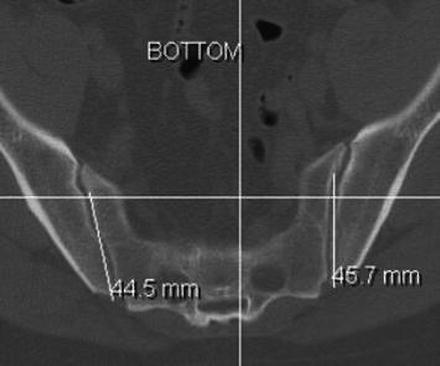
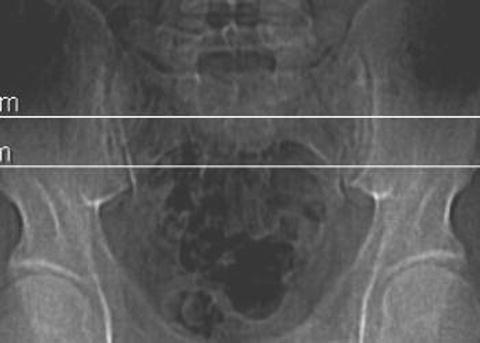
Fig. 10.2
Preoperative axial CT showing the caudal-most margin for total cage containment. Note that the measurement from the tip of the PSIS to the safe anterior aspect of the sacroiliac joint is shorter in this axial plane than in the previous more cephalad section
Utilizing CT scanner software, these margins are printed out as horizontal lines on an AP scout radiograph of the pelvis, appearing as the surgeon would visualize it with fluoroscopy in surgery. The space between the lines represents the “safe zone” (Fig. 10.3).
Now the surgeon has knowledge of the safest space to place cages from posterior into the longitudinal axis of the SIJ in both the coronal and axial planes. There is no useful imaging that will assist the surgeon with this approach in the lateral plane, as the SIJ cannot be reliably imaged laterally. If any of the preoperative preparation images cannot be obtained, this technique should be abandoned in favor of another procedure.
Step 2: Positioning
The patient is placed in the prone position taking the same standard precautions as for a lumbar fusion surgery and allowing the abdomen to hang free (see Fig. 9.4). Image is then brought in and an AP view of the involved SIJ is obtained to assure good visibility. This can usually be accomplished even in the most obese patient, as there is actually less soft tissue muscle and bony obstruction in this plane than in the lateral plane. The image is then moved live approximately 10–25° cephalad and, in the axial plane, posterior medial and anterolateral, until the best overall image of the joint is obtained. This becomes the angle of insertion for the cages and provides the last necessary angular information for the surgeon before beginning the operation.
Step 3: Incision
The most prominent tip of the PSIS is palpated, and a 1–2 in., depending on the size of the patient, vertical incision is made. This dissection is carried down to the bone. In an obese patient, the PSIS tip might not be felt externally and may need to be visualized with image after which the incision and blunt finger dissection are needed to physically feel the PSIS (Fig. 10.4).
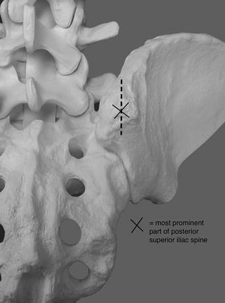
Fig. 10.4
The vertical incision is in line with and just cephalad and caudal to the PSIS
Step 4: Preparing the Space for the Cage
With the image remaining in position, a ¼ in. drill bit is then tapped into the bone of the PSIS with a mallet just far enough to hold it upright. Image is used to verify that the bit is in the lower 1/3 of the safe zone and aimed straight into the joint following the same angles as the imaging (Fig. 10.5).
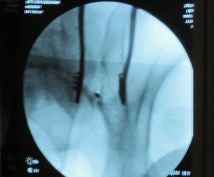
Fig. 10.5
Intraoperative AP image showing the drill bit aimed at the sacroiliac joint
The drill is then advanced through the PSIS and into the joint, frequently verifying with image that it is staying in the joint line. Once the depth, predetermined by preoperative CT scan, is reached, the drill is removed and a K-wire is placed, blunt end first, into the hole. The surgeon verifies with this that there is bone at the hole’s depth. After creating the channel for the inverted K-wire, the surgeon will have a good understanding as to the density of the subchondral bone. It is with this knowledge that he/she decides whether an awl can be used to make the channel larger or whether a power drill will be needed. A cannulated awl or drill bit is then placed over the K-wire, approximately 2 mm less in width than the cage that will be placed, and the hole is made larger to the same depth as the K-wire. This is when a lateral image becomes important. All that needs to be seen is the position of the tip of the blunt end of the K-wire. If, when using the awl or the drill to widen the channel, the tip of the K-wire moves, further drilling is stopped. The K-wire is removed and the hole is palpated to be sure that bone still remains at the base of the hole and no soft tissue is palpable.
Caution! If after measuring the channel appears to be deep enough for total cage containment to include some subsidence of it at the dorsal surface, the procedure can continue. If not the decision to make the hole deeper using a “free-hand” technique while watching the lateral image is an option, but only in the hands of a very technically capable and experienced surgeon keeping in mind that plunging through the anterior SIJ into the pelvis is potentially “life threatening”! We are not recommending that option here and our advice is that if there is any hesitation or concern on the part of the surgeon, another method to fuse the SIJ should be entertained.
All hardware is then removed and the hole is palpated to insure that bone is present both deep and all around the created canal. It is also visualized on image to assure that the created hole is inside the center of the joint line. We use a 9 mm-diameter awl or drill bit for an 11 mm-diameter cage placed at an average depth of 4.5–5.5 cm depending on the preoperative studies.
Step 5: Insertion of Cage
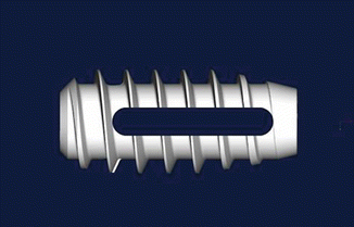
At our institution, the cages used in our study were custom (Medtronic) and filled with BMP (Infuse, Medtronic). With the hole properly prepared, the cage is then inserted to a depth of tightening by two fingers. It is then visualized on image in both the AP and lateral planes. A clamp is then placed on the dorsal aspect of the cage, and vigorous pulling is done to verify that the cage is indeed very stable. If it moves, then a larger cage must be inserted. The success of the cage placement is based on the concept of distracting the joint against the opposing tension forces of the intact anterior and posterior SIJ ligaments. If these structures are severely compromised, other methods for SIJ fusion should be considered (Figs. 10.6 and 10.7).