Posterior Cervical Microdiscectomy/Foraminotomy
Michael P. Kelly
K. Daniel Riew
INDICATIONS
The ideal candidate for a laminoforaminotomy is one who has radicular pain without constant numbness or profound weakness. This is because, with pain, one knows immediately postoperatively if the operation was a success. With constant numbness or weakness, it can take time for the deficits to resolve, and sometimes, it never improves. During that time, one wonders if the deficits are persisting because of inadequate decompression, irreversible deficits, or insufficient time for the nerves to recover. Magnetic resonance imaging (MRI) and even computed tomography with myelography may show persistent stenosis, but there is no way to know if further anterior surgery will help or not. Therefore, while we have performed laminoforaminotomies in patients with neurologic deficits, we do so with trepidation and warn the patient in advance of the downsides to doing this procedure in such cases.
We pay particular attention to the Spurling maneuver. We have found that the ideal candidate is one in whom doing the Spurling maneuver increases the pain whereas forward flexion eliminates it. If the pain persists upon forward flexion and the patient does not have a herniated disc, a simple foraminotomy is not likely to improve the pain. This is because a laminoforaminotomy will not alter ventral root compression from an uncinate spur when the patient flexes the neck postoperatively. The exam should include provocative maneuvers for compressive neuropathies, such as cubital tunnel and carpel tunnel syndromes, and shoulder pathologies, such as rotator cuff tendinitis and impingement syndrome.
After determining the level of the pathology, we often utilize transforaminal epidural steroid injections (TESI) or selective nerve root blocks as both a diagnostic and therapeutic intervention. As the therapeutic effects are inconsistent, we remind the patient to pay close attention to the relief achieved in the first several hours, while the local anesthetics are active.
Radiculopathy due to
Disc herniation causing foraminal stenosis
Uncinate hypertrophy causing foraminal stenosis
Facet joint (superior facet greater than inferior facet) causing foraminal stenosis
In our practice, a positive Spurling maneuver, with improvement upon flexion, predicts a successful posterior foraminotomy.
CONTRAINDICATIONS
Central compression.
Compressive pathology causing asymptomatic T2 signal intensity in spinal cord as seen on MRI.
Dynamic instability at the level undergoing decompression is a relative contraindication.
Not recommended for patients having undergone previous foraminotomy or laminectomy or those with a profound neurologic deficit.
PREOPERATIVE PREPARATION
One must understand the anatomy of the foramen, with the relations of the nerve root to the offending pathology (1,6). The lateral aspect of the spinal canal is bound dorsally by the inferior and superior lamina and the adjoining ligamentum flavum. The medial aspect of the facet joint defines the entry to the neural foramen. The superior and inferior borders of the foramen are the cranial and caudal pedicles, respectively. Ventrally, the foramen is bound by the intervertebral disc, the cranial vertebral body, and the uncovertebral joint. Dorsally, the foramen is bound by the facet joint, with 1 to 2 mm of the inferior facet of the superior vertebra and the entire superior facet of the inferior vertebra. Thus, compression can be from ventral uncovertebral hypertrophy, a soft disc, a “hard” disc-osteophyte complex, or facet joint hypertrophy.
Plain radiographs (anteroposterior [AP], lateral upright, lateral flexion/extension, obliques) (Fig. 8-1A-F) should be obtained prior to any higher-level imaging. The oblique radiographs are of particular utility when looking at the foramen, revealing both uncinate hypertrophy and facet joint osteophytes. MRI (Fig. 8-2A and B) should be used to identify areas of central and foraminal stenosis. An oblique, parasagittal view is ideal to visualize the neuroforamen (Fig. 8-2C). Often, the etiology of the stenosis can be determined as well (e.g., soft disc herniation, uncinate hypertrophy). In some cases, computed tomography scans may be used to identify disc-osteophyte complexes and ossification of the posterior longitudinal ligament. Coronal and sagittal reformats sometimes aid in surgical planning.
TECHNIQUE
We prefer to position the patient prone on an open Jackson frame (Orthopedic Systems, Inc., Union City, CA), with the neck flexed and the head held with Gardner Wells tongs in 15 pounds of axial traction. We will position the patient in reverse Trendelenburg, to encourage pooling of blood in the lower extremities to minimize blood loss and to bring the field into better view for the surgeon (Fig. 8-3). The support frames are placed at the top rung at the head and the bottom rung at the foot. This maximizes the reverse Trendelenburg position.
 FIGURE 8-1 A: Preoperative upright, AP radiograph. The patient is a 64-year-old gentleman with a right C4 radiculopathy that failed to respond to nonoperative interventions, including TESI. B: Upright lateral radiograph. C: Right oblique radiograph. D: Left oblique radiograph. |
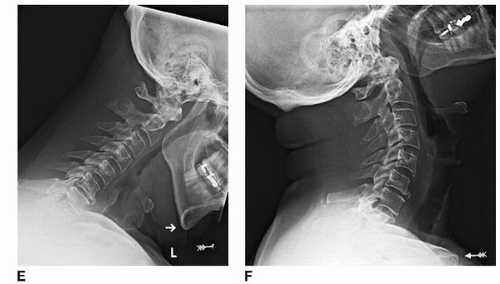 FIGURE 8-1 (Continued) E: Preoperative flexion radiograph. F: Preoperative extension radiograph. |
Some have advocated positioning the patient in an upright, “beach chair”-type position, though this raises the risk of an air embolus complicating the procedure. Blood loss is less, however. The main disadvantage is that it is somewhat less comfortable for the surgeon.
The chest and pelvis are supported with bolsters, and the legs are placed in a sling. The hands, wrists, and elbows are well padded and then secured to the sides of the patient with a sheet. Minimal traction is applied to the shoulders, and they are taped in this position. Pulling too hard on the shoulder will stretch the nerve and make it more difficult to mobilize the root if a discectomy is necessary.
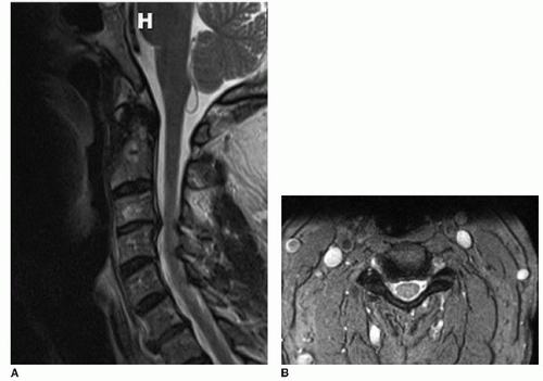 FIGURE 8-2 A: Midsagittal STIR MRI. B: Axial T2-weighted MRI at C3-C4. A right paracentral disc herniation is causing foraminal stenosis. |
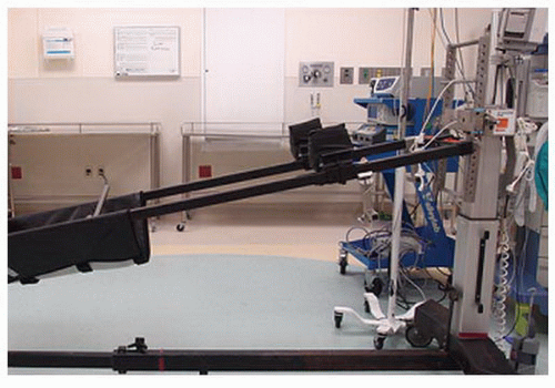 FIGURE 8-3
Get Clinical Tree app for offline access
Related posts:Stay updated, free articles. Join our Telegram channel
Full access? Get Clinical Tree


|


