Fig. 12.1
Total knee replacement after 18 years of implantation with massive wear of the tibial polyethylene insert
In order to improve the wear performance of TKR, local stresses need to be decreased or the wear resistance of the polyethylene material needs to be increased [11]. Different developments in materials and implant designs as well as in surgery techniques have been made in the past. Cross-linking of the molecular chains as well as the addition of vitamin E leads to delay of polyethylene wear [12]. Furthermore, the coating of the femoral component or materials like ceramic or zirconium oxide can contribute to an extension of the implant longevity [13, 14]. Implant design, particularly the degree of the tibiofemoral congruency, is assigned a crucial significance. The prevalent knowledge is that more conforming TKR designs with larger contact areas for transmission of contact forces have lower contact stresses [15–17] and may have reduced surface damage of the polyethylene insert in comparison to less conforming designs [18, 19]. In addition, the thickness of the tibial insert plays an important role in influencing contact stresses. An increase in thickness causes a decrease of the contact stresses and, therefore, a less severe surface alteration [17]. However, despite all technical efforts, it has not yet succeeded in ensuring a long-term, clinically harmless wear performance.
From a technical point of view, four main friction mechanisms according to the technical rule VDI 3822-5 [20] can be distinguished that are more or less marked at TKR: adhesive wear, abrasive wear, surface fatigue, and tribo-chemical wear.
Adhesive wear occurs especially in areas with a high surface pressure when the atomic bonding forces are stronger than the specific material properties of either surface and thereby pull out fragments from one surface to another [21].
Abrasive wear occurs when a harder and rougher surface slides and plows through a softer surface. Abrasive wear can be found between two surfaces with scattered hard particles interacting between them as well [22].
Surface fatigue is a process in which material near to the surface is weakened by cyclic shear stresses or strains that exceed the fatigue strength of the material. This friction mechanism initiates and propagates cracks at both the surface and subsurface [22].
Tribo-chemical wear is a process with a chemical basis that occurs at the interface between the articulating components and the environment. During motion, reaction products are permanently produced and rubbed off [22].
Four wear types can be seen in TKR. These are adhesive wear, abrasive wear, surface fatigue, and tribo-chemical wear.
In TKR these friction mechanisms lead to different macroscopic signs of wear at the contact zone, mainly at the frictional partner with the lower Young’s modulus of elasticity, i.e., the polyethylene insert. The severity, location, and type of signs can be correlated with the geometry of the articular surface, component thickness, material behavior, clinical data, and surgical factors such as implant position and orientation [11, 16, 17]. In order to evaluate the extent and severity of the surface alterations, a partition system of Hood et al. is prevalently used [23]. It is based on a separation of the components into different regions and a scale to grade the damages. This enables a comparison of the same regions from various TKR designs [24–26].
In the following sections, the most important signs and patterns of wear at the articulating surface between femoral component and tibial insert made of polyethylene are documented and described by means of macroscopic and high-scaled pictures of retrieved components. In addition, a section according to the wear mechanisms of the central bushing of hinged total hip replacement designs is listed at the end of this chapter.
12.1 Patterns of Wear at the Articulating Surfaces of the Femoral Component and Tibial Insert
12.1.1 Burnishing
A less severe sign of wear in TKR is burnishing [27]. Contact areas are polished due to a combination of abrasive and adhesive wear. Manufacturing-related machining marks on the surface of the component are erased [27, 28], resulting in a large contact area (Fig. 12.2a–c) [23]. The increased conformity of the surfaces thus causes low stress magnitudes associated with less surface damage [17]. Nonetheless, the particles generated by adhesion mostly are of submicrometer in size, which may lead to adverse cellular reactions in the surrounding tissues, causing macrophage activity and osteolysis at the implant-bone interface [29, 30].
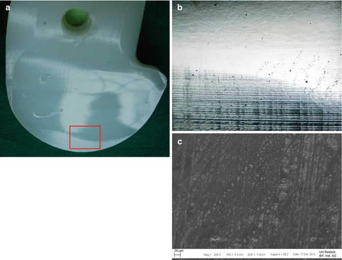

Fig. 12.2
(a) Tibial polyethylene insert with evidence of burnishing in the loaded area. The indentations shown on the articulating areas originate from explantation. Microscopic view of the red rectangle is illustrated in (b). (b) The highlighted area from (a) is illustrated in higher solution. The picture clearly shows the interface of the horizontal manufacturing-related machining marks (at the bottom) and the smoothened area (at the top). (c) High-scaled illustration by means of Field Emission Scanning Electron Microscopy (FESEM) of the interface with machining marks at the right side, passing here from bottom to top
Burnishing of the polyethylene component is a less severe sign of wear in TKR. Generated wear particles are of submicrometer in size and can provoke immunological response.
12.1.2 Scratching
Scratching is a mode of damage caused by abrasion. Differences in roughness and hardness of the articulating partners lead to a plowing of the surface of the softer material during the relative joint motion (Fig. 12.3a–c) [24]. The surface alteration, characterized by striated lines, is primarily formed in the main direction of stress (anterior-posterior) [31, 32]. Scratching is one of the dominant damage modes at the backside of mobile-bearing polyethylene inserts [25, 26, 33]. In contrast to the tibiofemoral articular surface, the scratches at the lower mobile-bearing surface (backside wear) are in a shape of concentric rings [26].
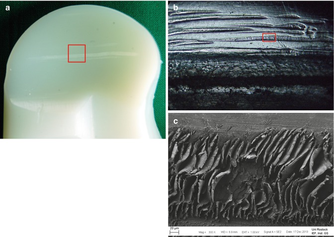

Fig. 12.3
(a) Macroscopic picture of a retrieved tibial polyethylene component with some scratches in the anterior-posterior direction. Microscopic view of the red rectangle is illustrated in (b). (b) Example of scratching from the highlighted area of (a). FESEM picture of the red rectangle is illustrated in (c). (c) FESEM illustration with high solution of the plowed area of the scratch
Scratching is a type of surface alteration that is caused by abrasive wear.
12.1.3 Pitting
Pitting is one of the most frequent types of surface alteration seen on retrieved ultra-high-molecular-weight polyethylene (UHMWPE) components [23, 34]. This mode of fatigue wear is controlled by the maximum of contact stresses [16, 17, 35] and causes cracks that emanate at the surface and then propagate into the UHMWPE component [34]. The resulting fragments are detached from the surface via adhesive processes. The contact surface shows characteristics similar to a crater area (Fig. 12.4a–c) whose severity depends on the degree of conformity, implantation duration, and intensity of the loading [17, 36]. Wear debris produced by pitting is considered to be too large (1–2 mm in diameter) to provoke immunological response and therefore, from a biological view, a more benign wear mechanism regarding osteolysis [24].
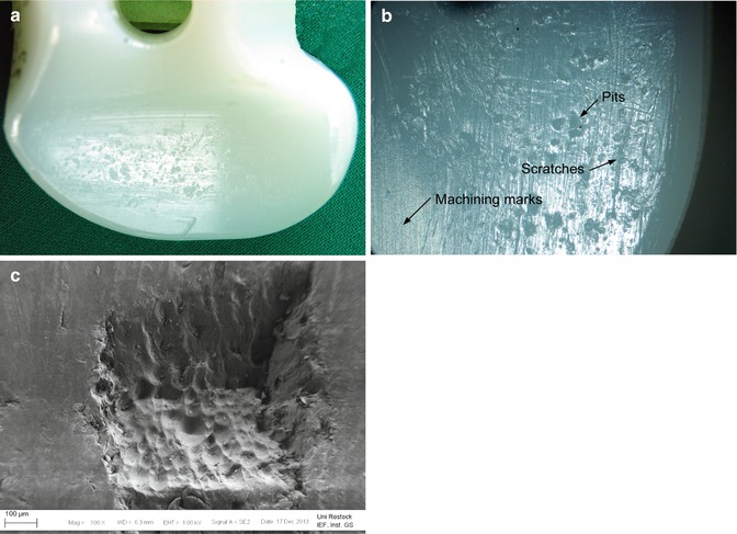

Fig. 12.4
(a) Disrupting area at the articulating surface that is characteristic of pitting. (b) Pitting area in higher solution with scratches and machining marks. (c) FESEM image of a pit at the articulating surface of a retrieved polyethylene inlay
12.1.4 Delamination
The continuous dynamic combination of rolling and sliding leads to an elastic deformation of the UHMWPE in the contact area. The maximum principle stress, acting tangent to the surface, and the maximum shear stress (maximum values 1 mm beneath the articulating surface) wreak subsurface cracks, which propagate in a tangential path relative to the surface (Fig. 12.5) [17, 37]. When loading duration increases, flakes can be sheared out of the UHMWPE component that may result in catastrophic wear (Fig. 12.6a–c) [28, 38].
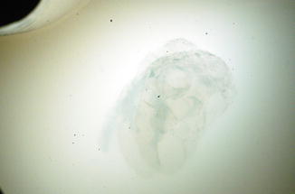
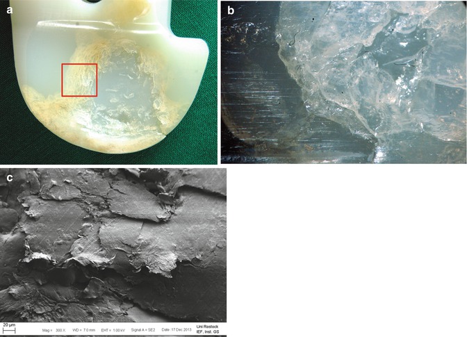

Fig. 12.5
Example of a beginning delamination process, initiated with subsurface cracks

Fig. 12.6
(a) Retrieved tibial polyethylene insert with evidence of delamination. Microscopic view of the red rectangle is illustrated in (b). (b) Highlighted region from (a) showing the fragments similar to flakes that are typical for delamination. (c) FESEM image of a delamination area
Subsurface oxidation is considered to be another cause for delamination of polyethylene [39, 40]. The oxidation can be initiated during the sterilization process by the use of gamma irradiation in air [41–43] as well as in an inert gas environment [44, 45] and may lead to a subsurface degradation of the polyethylene material [38].
12.1.5 Third-Body Wear
Within different wear mechanisms in the artificial joint, third-body wear is a serious problem [46–48]. Debris left in situ during surgery can act as third-body particles initiating the wear process postoperatively by rubbing at the bearing surfaces leading to the surface damage (scratches) and wear particle release by scraping [47]. For example, residual bone cement, bone fragments, worn metallic particles, and residuals on implants such as ceramic particles from the corundum blasting process can function as third-body wear particles in between the articulating surfaces of the TKR. An enormous increase in wear and damage of the bearing surfaces caused by third-body particles has been described in experimental simulator studies [32, 49]. Deep visible scratches on the implant surfaces and left embedded particles inside the articulating surfaces (Fig. 12.7a–c) indicate abrasive third-body wear caused by large particles. The visible appearance of third-body wear depends on the size of the particles. Bone cement particles can range from 250 to 340 μm [46] and can generate visible macroscopic damages, while metallic particles generated during resection were considerably smaller (3 μm) [50] and third-body wear can only be detected microscopically.
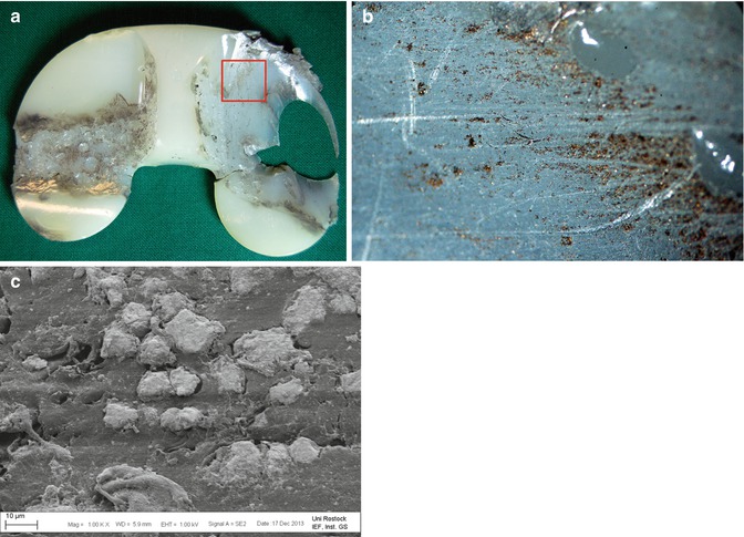

Fig. 12.7
(a) Tibial polyethylene insert with examples of delamination (left) and third-body wear. The highlighted region shows embedded third-body particles. Microscopic view of the red rectangle is illustrated in (b). (b) Microscopic image from the highlighted area of (a) with third-body particles, embedded in the surface of the polyethylene tibial insert. (c) High-solution image of embedded metal particles that may initiate third-body wear
Wear debris left in situ during surgery can act as third-body particles initiating the wear process postoperatively by rubbing at the bearing surfaces of the femoral component and the polyethylene insert.
12.1.6 Creeping
Creeping is a damage mode that describes the irreversible exceeding of the yield strength of the UHMWPE material under physiological loading [51]. As a result, the component deforms plastically without release of wear debris (Fig. 12.8) [52]. More severe plastic deformations, mostly at the tibial insert, may be an indication for a malalignment or a mismatch of the chosen component sizes. Moreover, the changing of implant geometry may lead to joint instabilities [53].
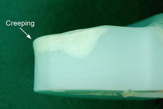

Fig. 12.8
Creeping at the cranial-medial edge region of a retrieved tibial polyethylene inlay
The most important patterns of wear at the articulating surfaces of TKR are burnishing, scratching, pitting, delamination, and third-body wear and creeping.
12.2 Wear at the Bushings of Hinged or Rotating-Hinged TKR
Failure of the bushing of the central axis at hinged implants or of the bushings of rotating-hinged implants, which are often used in case of revision and tumor surgery, is a common pattern of wear in modular TKR [54–56]. The guided connection between the femoral and tibial component provides excellent knee joint stability and offers mostly the only solution to retain mobility. Due to the limited degree of freedom and less conforming condylar contact zones, stress from shear and torsional loading is, however, transferred directly to the hinge and may lead to a failure of the bushings [57–59]. Retrieved polyethylene bushings showed indications for insufficient creeping [55] and massive wear [60], which require revision surgery. Some implant manufacturers have changed the bearing of the hinge to a polyethylene covered trial hinge axis articulating against the mounting at the backside of the femoral component. However, the trial hinge axis can also wear out (Fig. 12.9a, b).
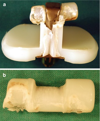

Fig. 12.9


(a) Tibial insert of a hinged TKR with massive wear at the polyethylene covered trial hinge axis. (b) Detailed view of the hinge axis with marks of massive wear laterally as well as centered within the mounting area to the metallic tibial component
Stay updated, free articles. Join our Telegram channel

Full access? Get Clinical Tree


