Fig. 61.1
Sensorized surgical tools, used for RTKR navigated surgical procedure: (a) reference arrays to be fixed on the femur and on the tibia to allow the tracking of the two bones during the surgery and to correlate their position with the position of the surgical instruments; (b) pointer used to digitize the needed anatomical reference; (c) the FemoralMod and the TibialMod. These are two tools developed to provide the system with information on stem orientations and to navigate some cutting guides during the intervention; (d) custom-made spacer, to spread the joint for the estimation of the space in flexion and in extension. It is used with the FemoralMod and the TibialMod correctly positioned on the bones. This tool allows one to estimate the space, taking into account ligaments’ constraints and, together with the graphical tools implemented by the system, enables the surgeon to perform a navigated ligament balancing
3.
Two special tools were developed, called the FemoralMod and the TibialMod, to acquire the direction of the medullary canal of the two bones and to provide indications for a correct rotational and anteroposterior TKR positioning (Fig. 61.1c).
4.
A custom-made spacer, called KeyTensor (Fig. 61.1d), is used to measure the gap between the femur and the tibia in flexion and in extension.
During gap acquisition, KeyTensor features allow the femur and the tibia to assume a position depending exclusively on ligament constraints, enabling the surgeon, together with the information provided by the software, to perform a navigated ligament balancing.
The system does not require preoperative medical images. Moreover, landmarks needed to navigate during surgery are acquired after TKR removal.
Joint line computation and gap measuring steps implemented within the system are independent from the surgical instrumentation used, while virtual planning phase and implant positioning navigation depends on the TKR prosthesis model.
61.2.2 Surgical Technique
After performing the surgical approach, the two reference trackers are fixed to the bones using two bicortical pins. It is mandatory to avoid possible impingement between the bicortical pins and the cutting guides or femoral and tibial intramedullary rods. On the tibial side, this can be obtained by positioning the two pins in the anteroposterior (AP) direction distally on the tibial shaft, below the hypothetical position of the intramedullary rod tip. On the femoral side, the two pins can be positioned in the AP direction on the medial femoral metaphysis. Moreover, both on the femur and on the tibia, the trackers can be fixed after the canal reaming with the intramedullary rod inside the bone.
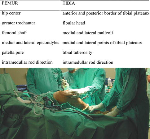
After TKR removal and medullary canal reaming, the surgeon, using the sensorized instruments, detects several anatomical landmarks on patient anatomy, medullary canal direction, and the tibial and distal femoral residual planes’ orientation (Fig. 61.2). Using those data, RTKR-Nav reconstructs the 3D representation of the patient’s lower limb and the references to plan the intervention.


Fig. 61.2
Anatomical data required to build a patient model and to plan further surgery. Even if, during acquisition phase, some specific points were missing due to the bone deficiencies (e.g., one or both of the epicondyles). For each TKR component, several criteria to set each degree of freedom are considered and compared, and the system is always able to suggest an intervention plan
Using the conventional surgical technique, tibial and distal femoral resection should be performed to the level required to establish a viable surface and preserve bone stock. On the femoral side, augmentation can be employed to correct possible imbalance.
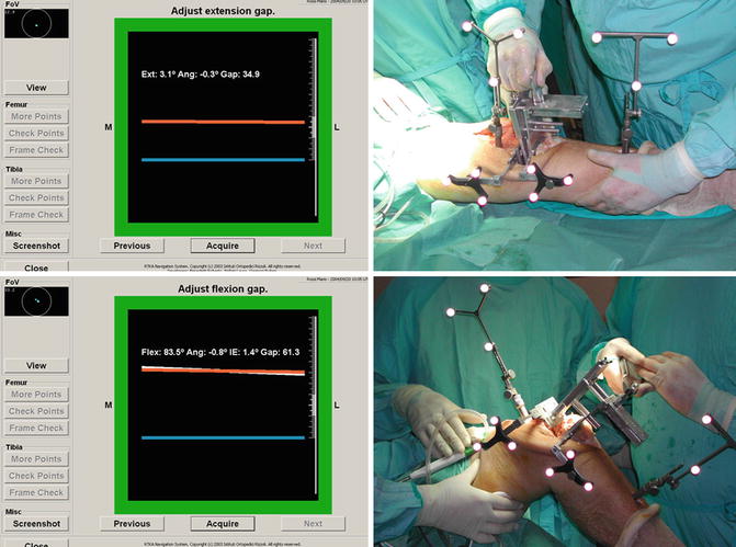
Gap measurements in extension and in flexion define the surgical strategy: with the FemoralMod and the TibialMod positioned on the bones, with the relative planes tangent to the most protruding part of each bone, using the KeyTensor to obtain the desired ligament tension, joint space measuring in extension and in 90° of flexion is performed, and the symmetry of each gap is evaluated (Fig. 61.3).


Fig. 61.3
Estimation of extension and flexion space using the KeyTensor. During extension gap evaluation, the limb is positioned in extension and the KeyTensor is used to create the gap; the TibialMod reference (blue line), representing the tibial residual plane in the frontal view, and the FemoralMod reference (orange line), representing the distal femoral residual plane, are shown on the interface together with numerical data to assess the gap extent, the parallelism between the two planes, and if ligament release is required. During flexion space estimation, with the limb at 90° of flexion the KeyTensor is used to create the gap between the two bones; on the interface, the TibialMod reference (the same as in extension) and the FemoralMod reference (representing the mediolateral direction of the femoral prosthesis that will be implanted) are shown together with the transepicondylar line reference (upper white line) to determine proper femoral prosthesis rotational positioning with respect to both anatomical reference (transepicondylar line) and to the soft tissue balancing
RTKR-Nav shows on the interface the relative positions between mediolateral axis of the two planes together with the numerical information about their distance and the angle between them in the frontal plane, updated in real time.
61.2.3 Planning Criteria
An acceptable joint line level is determined with regard to medial and lateral epicondyles height, the patella pole position in extension, and the fibular head [25, 29–33]. The optimal joint line height is set. The measured extension space defines the required tibial polyethylene insert size and possible need of femoral augmentation. The optimal tibial polyethylene insert size chosen is the one that fits best the space between the tibial cut and the joint line height determined.
The femoral component size to be implanted in order to have a correct flexion-extension soft tissue balancing is determined. This should consider the flexion space, the prosthesis features, and the relationship between the canal position and the anterior femoral shaft [25, 31, 34, 35].
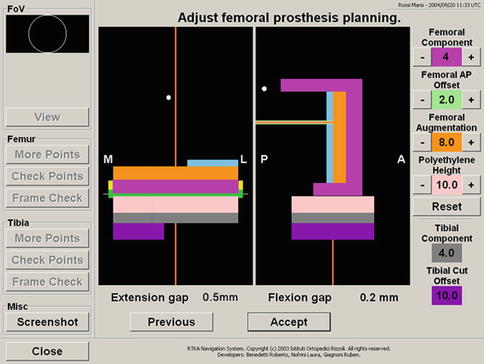
The navigation system proposes an intervention plan and provides the surgeon with tools to analyze and modify the proposed plan. It can also monitor the behavior of the residual joint gap in flexion and in extension (Fig. 61.4).


Fig. 61.4
System interface while planning. The system plans the best joint line position considering the relationship that it should have with respect to the acquired anatomical references. Once the joint line position is defined, the system plans the femoral and tibial prosthesis size and augmentations required to balance the gaps. Each TKR component is represented by a simple geometrical model, which is drawn considering only the characteristics useful for planning purposes. The limb is represented by the femoral and tibial mechanical axis together with some reference points useful for planning refinement. The joint line is represented by a white line. For each anatomical reference, the optimal position of the joint line with respect to that reference is represented with a green rectangle centered at a distance from the relative reference equal to the mean distance value between the two data reported in literature and a height equal to the reported standard deviation. The area where those rectangles are superimposed is drawn in yellow, representing the area where most of anatomical conditions for joint line position are satisfied. The initial planned joint line position is drawn in the middle of the yellow area. Using the buttons on the interface, the system allows the surgeon to modify the prosthesis’ size components and to check different components, combinations, monitoring the consequences on joint line position and residual gap in extension and in flexion. After definition of the optimal surgical plan, specific tools enable the surgeon to correctly position the cutting guides in order to reproduce the planned strategy. The final position of the tibial and femoral TKR can be checked by displaying the postoperative leg alignment and residual joint gap
It needs to be underlined that, even if during the acquisition phase some specific points are missing due to bone deficiencies (e.g., one or both the epicondyles), because for each prosthetic component several criteria to set each degree of freedom are considered and compared, the system is always able to suggest an intervention plan.
61.3 RHO Navigation System for Hinged TKR
Hinged prostheses for revision TKR are used in cases of severe bone loss, instability, insufficiency, or the absence of one or both collateral ligaments and chronic dysfunction of the extensor mechanism. Proper implant positioning and correct joint line position are crucial for a successful outcome. A specific software for navigation of hinged TKR, called RHO, was developed in collaboration with Orthokey, and now it is included in the set of applications available with the BLUIGS platform (BLUIGS, Orthokey, Lewes, DE, USA).
RHO assists the surgeon in restoring the joint line level based on the remaining anatomical landmarks available and recreates the correct rotational positioning of the TKR.
61.3.1 System Description
RHO is based on the use of an optical localizer and some sensorized instruments tracked during the surgery. The sensorized instrumentation consists of two reference arrays (to be fixed to the femur and to the tibia) and a pointer used for anatomical landmark acquisition. Any conventional TKR instrumentation can be used for surgery without any problems. As with RTKR-Nav, for RHO, preoperative medical images are not required, and all the computations are based on the anatomical acquisitions done after primary TKR removal.
61.3.2 Surgical Technique
After the surgical approach, the femoral reference array has to be fixed to the medial distal femoral metaphysis using two monocortical screws. Then, the tibial array is fixed as distally as possible on the shaft with two bicortical 3 mm ∅ screws.
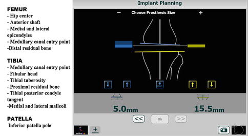
Anatomical landmark acquisition is performed after primary TKR removal, and starting from those points, RHO reconstructs the best joint line level for both the tibia and femur (Fig. 61.5). In this case, because a hinged prosthesis is implanted, best joint line position is reconstructed using only anatomical data.


Fig. 61.5


RHO landmarks acquisition and joint line planning interface. After landmark acquisition, the system shows on the interface the optimal joint line position (white line) with respect to femoral and tibial references and the areas where joint line anatomical constraint are satisfied. The criteria to define the best joint line position are close to the ones described for RTKRNav: for each anatomical reference acquired, the optimal position of the joint line with respect to that reference is represented with a rectangle (blue for the femoral references and yellow for the tibial one) centred at a distance from the relative reference equal to the mean distance value between the two data reported in literature and height equal to the reported standard deviation. The area where those rectangles are superimposed is drawn with a dark colour, representing the area where most of anatomical conditions for joint line position are satisfied. The initial planned joint line position is drawn in the darkest area of the two sets. Even when some registry points were missing, because several criteria are considered and compared, the system is always able to suggest a solution.
Stay updated, free articles. Join our Telegram channel

Full access? Get Clinical Tree


