Mobility Implant: Features, Technique, and Results
Pascal Rippstein
INTRODUCTION
The Mobility total ankle system is a cementless, unconstrained three-component mobile-bearing ankle prosthesis, which has been designed by three surgeons—Chris Coetzee, Pascal Rippstein, and Peter Wood. Its design has been mainly inspired by the Buechel- Pappas prosthesis, which has been successfully used by two of the authors, in conjunction with the experience gained with two other prostheses—the Scandinavian total ankle replacement (STAR) and the Agility. The goal of the designers was not to “reinvent the wheel” with the Mobility but to improve what has been found to need improvement regarding implant design and ancillary procedures. The Mobility was first implanted in 2003 and was commercially launched 1 year later after a successful initial clinical trial.
TIBIAL COMPONENT
The backsides of the tibial and talar components are made out of cobalt-chrome with a Porocoat porous coating surface which allows bone in-growth. The tibial component has a flat articular surface and a stem on its tibial side. This short conical intramedullary stem allows the final rotational adjustment of the tibial component after its insertion through an anterior window in the tibia (Fig. 7.1). The stem provides initial stability to the tibial component, and the stability can be increased by impacting cancellous bone around the stem if needed. The tibial plate has been designed relatively long in the anteroposterior (AP) direction to allow for optimal support on both the anterior and the posterior tibial cortices. The posterior part of the plate is narrower and rounded to avoid impingement with the malleolus lateralis and the medial soft tissues. The tibial component comes in six different sizes and can be used for either the left or the right ankle.
TALAR COMPONENT
The talar dome resection is minimalized with three flat cuts on its dorsal surface and with no resection on its lateral and medial walls. One advantage of retaining the lateral and the medial articular surfaces of the talar dome, in addition to providing more physiologic ankle biomechanics, is that the intact medial and lateral walls provide (with their cortex) improved support for the talar component, reducing the risk of secondary subsidence or migration. Furthermore, if the Mobility needs to be removed for a secondary ankle fusion, the intact malleolar joints provide a narrow joint space which will easily fuse and will contribute to the stability of the ankle fusion. Therefore, the bone graft used to fill the central defect left by the removed Mobility does not need to provide as much support and the limb shortening can be reduced to a minimum.
Since the talar component is not “covering” the talar walls, one can check during the implantation if the component is fully seated on the talus dome. Thus, any dead space in the interface between the bone and the implant can be eliminated.
 Figure 7.1. Mobility ankle replacement. Used with permission from DePuy-Synthes, Warsaw Indiana. |
The remaining bone stock of the talar dome is usually sufficient to allow a good anchorage for screws, making an isolated ankle fusion possible without having to include the subtalar joint in the fusion. The subtalar joint will remain functional as an important joint to compensate the lost motion at the ankle during gait.
Even if inversion and eversion motions have been shown not to be significant after the implantation of a Mobility ankle, the doubly curved shape of the articular surface of the talar component allows articular congruence during those motions and stabilizes the polyethylene insert (Fig. 7.1). If the talar component has not been implanted perfectly parallel to the ground surface, then at least one of both “wings” of the talar component will compensate this obliquity, being more or less horizontal, that is, parallel to the floor, and preventing the prosthesis to “slide” toward one side or the other.
The talar component is available in six sizes. The sizes 1 to 4 and the sizes 5 and 6 require the same cuts on the talar dome for their implantations. This allows the surgeon to decide the best talar component size at the time of the implantation and provides for optimal talar support. It is not possible to switch between sizes 4 and 5 since the cuts are different for the size series 1 to 4 and 5 and 6.
POLYETHYLENE
The mobile bearing of the Mobility is made out of a highly cross-linked polyethylene inlay. The surface of the tibial side of the inlay is slightly smaller than the surface of the corresponding tibial component to prevent any overhang, even in the case of an imperfectly aligned tibial and talar components. This prevents friction of the polyethylene on the edge of the tibial component, which can lead to increased wear. The shape of the Mobility allows centering of tibial and talar components with respect to each other in both the sagittal and the frontal planes, preventing also the overhang of the polyethylene and allowing a more physiologic ankle motion.
TECHNIQUE
APPROACH
Make a longitudinal incision of some 15 cm, centered on the ankle, protecting the branches of the superficial peroneal nerve (Fig. 7.2). Incise the retinaculum extensorum over the extensor hallucis longus (EHL) tendon and try to keep the tibialis anterior (TA) tendon hidden in its sheet. In case of wound healing problem, it is better to have the EHL tendon exposed than the TA tendon, since a tendon resection might be needed and the functional loss with the EHL is less important than the one with the TA. Retract all the soft tissues lateral to the EHL tendon with the EHL tendon on the lateral side and protect this way the deep neurovascular bundle. Incise longitudinally the ankle capsule and retract the periosteum from the tibia on the lateral and the medial sides to visualize clearly the lateral and the medial borders of the ankle, which is of importance for the correct sizing of the components. Detach the periosteum from the tip of the malleolus medialis up to some 2 to 3 cm proximally, and generously cut the inner fibers of the deltoid ligament to reduce the medial stress on the malleolus medialis, which might produce a chronic anteromedial pain. Check for any osteophytes on the tip of the malleolus medialis and lateralis and remove them since they are frequently responsible for focal pain at this level. Make sure not to extend the soft tissue dissection too far lateral and distal since this could result in an iatrogenic lateral instability (injury of the ligamentum fibula-talare anterius). Remove generously any osteophyte on the anterior lip of the tibia with a wide osteotome to visualize the joint line on the tibia side. This joint line is an important landmark for the correct positioning of the tibial component. The dorsal aspect of the talar neck is frequently filled with new bone formation. Remove this additional bone to “recreate” the original talar neck and allow the talar component to sit correctly on the talus dome later in the case.
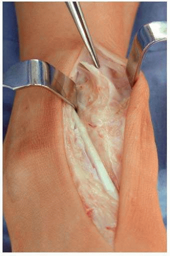 Figure 7.2. Anterior approach to the ankle. (From Easley ME. Operative Techniques in Foot and Ankle Surgery. Philadelphia, PA: Lippincott Williams & Wilkins; 2011, with permission.) |
EXTERNAL TIBIAL ALIGNMENT GUIDE
The cut on the tibia should be parallel to the floor. To achieve this, use two landmarks: the long axis of the tibia and the ankle joint line on the tibia side. The long axis of the tibia is frequently, but not always, perpendicular to the floor. This needs to be correctly assessed since the tibia is one of the landmarks that will be used to position the tibial alignment guide. It is therefore mandatory to have preoperative full-length mechanical axis radiologic views to rule out the incorrect position of the tibial alignment guide (Fig. 7.3). Draw on this full-length view a line starting from the middle of the ankle joint and running proximally perpendicular to the floor. This line will cross, in most cases, the tuberositas tibiae; if so, then the yoke will have to be pinned on the tuberositas. If not, then the distance between the tuberositas and the line should be noted and the yoke will have to be pinned at this distance from the tuberositas.
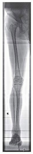 Figure 7.3. Full-length mechanical axis views to rule out proximal malalignment. (From Easley ME. Operative Techniques in Foot and Ankle Surgery. Philadelphia, PA: Lippincott Williams & Wilkins; 2011, with permission.) |
Ankle joint line at the tibia: note on the full-length views the orientation of this line in relation to the floor, considering only the intact part of the joint line if there is any erosion of the tibial plafond on the one or the other side. The joint line will be, in most cases, parallel to the floor. Place the tibial resection in regard to this information and pin it into the tibia to get a cut parallel to the floor.
These two landmarks are not totally accurate and should therefore be used in combination and integrated to get the best possible position of the tibial resection guide.
To obtain the correct slope, adjust the tibial alignment guide parallel to the anterior crest (Fig. 7.4). This has been shown to be very accurate.
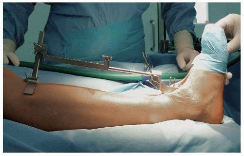 Figure 7.4. External tibial alignment guide parallel to the tibial shaft axis. (From Easley ME. Operative Techniques in Foot and Ankle Surgery. Philadelphia, PA: Lippincott Williams & Wilkins; 2011, with permission.) |
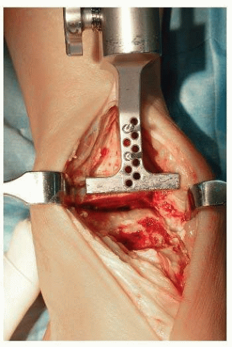 Figure 7.5. Initial tibial preparation, cutting block set for initial resection. (From Easley ME. Operative Techniques in Foot and Ankle Surgery. Philadelphia, PA: Lippincott Williams & Wilkins; 2011, with permission.) |
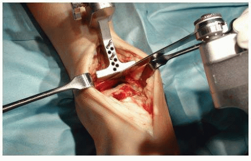 Figure 7.6. Initial tibial preparation with oscillating saw. (From Easley ME. Operative Techniques in Foot and Ankle Surgery. Philadelphia, PA: Lippincott Williams & Wilkins; 2011, with permission.) |
TIBIAL PLAFOND RESECTION
The tibial resection guide is secured with two pins into the tibia. A series of holes allow for the adjustment of the resection guide more proximal or distal by increments of 2.5 mm (Fig. 7.5).
Resect the tibial plafond with an oscillating saw, taking as much bone as needed for the implantation of the tibial component (Fig. 7.6). Make sure not to extend this cut into the malleolus medialis, weakening this way the malleolus medialis (risk of fracture!). The resected bone is still attached on the medial side to the malleolus medialis, and a vertical cut is needed now to remove it (Fig. 7.7).
With a small osteotome, remove the anterolateral part of the resected tibia, introduce a lamina spreader into this defect, and distract the ankle joint. This will give a better view into the ankle and allow to perform the vertical cut on the medial side without injuring the medial malleolar joint with the saw blade.
Using a reciprocating saw, make a vertical cut, that is, a vertical extension of the medial gutter of the ankle, and remove the resected bone.
Insert the joint thickness trial into the joint (Fig. 7.8). The tension achieved with this trial reproduces the final tension which will be achieved with the prosthesis in place and the thinnest mobile polyethylene bearing (3 mm). Correct resection will be achieved when the joint thickness trial can easily be introduced without tension and can be slightly wobbled, indicating that the final polyethylene thickness will be most probably 5 mm (which would allow to downsize the polyethylene to 3 mm if required). If the tension is not adequate, further bone resection is required, which is performed by moving proximally the tibial resection guide (Fig. 7.9A, B).
 Figure 7.7. Vertical cut to complete initial tibial cut (protects medial malleolus from potential fracture). (From Easley ME. Operative Techniques in Foot and Ankle Surgery. Philadelphia, PA: Lippincott Williams & Wilkins; 2011, with permission.) |
 Figure 7.8. Gap template matches thickness of tibial base plate and the thinnest polyethylene bearing. (From Easley ME. Operative Techniques in Foot and Ankle Surgery. Philadelphia, PA: Lippincott Williams & Wilkins; 2011, with permission.) |
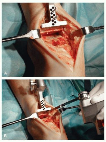 Figure 7.9. A: Cutting block moved 2 mm more proximally on same pins to allow greater resection in same plane as initial cut. B: Repeat resection. (From Easley ME. Operative Techniques in Foot and Ankle Surgery. Philadelphia, PA: Lippincott Williams & Wilkins; 2011, with permission.) |
TIBIAL AND TALAR SIZING
The tibial sizing gauges (sizes 1 to 6) have the same width as the corresponding tibial and talar components (Fig. 7.10A-E).
Choose the tibial sizing gauge that will just cover both the lateral and the medial borders of the talus. This gauge indicates the correct size of the talus component. If any doubt, always downsize the component to prevent any potential impingement between the talar component and the malleoli.
The correct size of the tibial component will frequently be one size larger than the talar one or the same size. Start with a tibial sizing gauge one size bigger than the one previously determined for the talus.
Hook the lip of this tibial sizing gauge behind the posterior aspect of the resected distal tibia. The anterior part of the gauge should cover the anterior aspect of the resected distal tibia. A small overhang is not a problem.
Check for any impingement between the gauge and the fibula, the gauge being well centered on the talus. If the gauge is in too lateral, this indicates that the resection has been insufficient medially. Proceed to an additional medial
resection with a small sharp osteotome until the gauge can be perfectly centered on the tibia. If the impingement with the fibula persists, then downsize the component to the same one as for the talus since an impingement with the fibula cannot be accepted (painful).
There are six sizes of talar and tibial components. The size of the talar implant must match or be smaller than the tibial implant.
Subsequent tibial cuts will be specific to the size of implant selected at this stage.
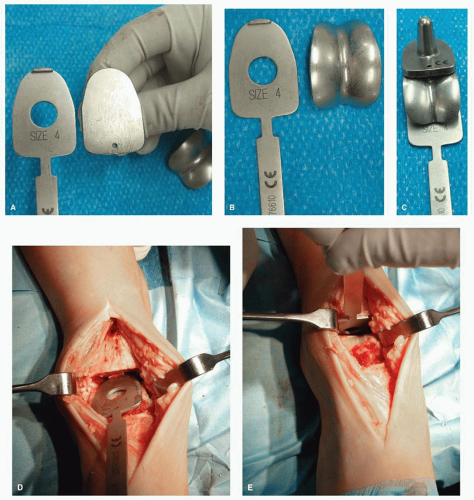 Figure 7.10. A-E: Tibial sizing. A: Tibial sizing gauge adjacent to corresponding tibial trial. B: Tibial sizing gauge next to talar trial. C: Corresponding tibial sizing gauge, tibial trial, and talar trial. D: Gauge being introduced to joint. E: Gauge hooked on posterior tibial cortex. |
TIBIAL WINDOW RESECTION
Mediolateral Positioning of the Prosthesis
Tibial and talar components should be aligned one in regard to the other. On the AP view, the only correct position for the talar component is the center of the talus dome. The tibial component—a flat surface—does not have such a precise position to follow. It will therefore follow the position of the talar component for its alignment (regarding the lateral-medial position of the prosthesis, we could say that “the talar component is the king who decides where the tibial component has to sit”). The tibial window for the tibial component should therefore be accurately opened over the center of the talus. It will later lead the implantation of the talar component. This step of the surgical procedure is therefore of crucial importance and should be performed meticulously.
Select the tibial template corresponding to the size determined by the gauges used for sizing and fit the tibial window cutting block to it (Fig. 7.11).
Place the assembly flush on the prepared tibial surface, with the tibial template flat on the resected plafond and the tibial window cutting block against the anterior tibia (Fig. 7.12). Make sure that the template is perfectly centered on the talus dome regarding its lateral-medial position, remembering that the tibial window will determine the further position of the talar component!
Use the appropriate drill to prepare the proximal part of the window.
Insert the tibial window peg to stabilize the tibial window cutting block.
Using the thinnest available saw blade to obtain the best possible press fit for the definitive tibial component, cut the lateral and the medial borders of the window, making sure that the saw blade is flush with the sides of the cutting block (Fig. 7.13). The two cuts should be deep enough to allow the later extraction of the bone block corresponding to the side of the chosen tibial size.Related posts:
 Walking Mechanics Following Surgical Interventions for Ankle Arthritis
Patient Selection, Surgical Indications, and Preoperative Planning
Management of Anterior Translation of the Talus During a Total Ankle Replacement
Complications After Total Ankle Replacement
Polyethylene
Conversion of Painful Ankle Arthrodesis to Total Ankle Replacement
Walking Mechanics Following Surgical Interventions for Ankle Arthritis
Patient Selection, Surgical Indications, and Preoperative Planning
Management of Anterior Translation of the Talus During a Total Ankle Replacement
Complications After Total Ankle Replacement
Polyethylene
Conversion of Painful Ankle Arthrodesis to Total Ankle Replacement

Stay updated, free articles. Join our Telegram channel

Full access? Get Clinical Tree


