The Zimmer Trabecular Metal Total Ankle System: Features and Techniques
Stuart H. Myers
Lew C. Schon
INTRODUCTION
DESIGN FEATURES
The Zimmer Trabecular Metal (TM) total ankle implant has numerous design features that distinguish it from other total ankle systems. An essential difference of this system is that it uses a lateral approach to reach the talocrural joint instead of the standard anterior approach. The implant, its method of insertion, and the ability to address associated pathology and malalignment stem from the opportunities made possible with this surgical vantage point. The altered perspective of the anatomic, physiologic, and biomechanic properties of the native joint permits design opportunities in accordance with these elements that may lead to a more versatile and enduring prosthesis.
Perhaps most demonstrative of this change from anterior to lateral relates to the bony preparation to create the ideal void for the TM device. Because of the lateral approach, each surface can be milled with a router, following the natural contour of the concave distal tibia and convex dome of the talus. The radius of the tibial and talar cuts based off the central axis, roughly approximated by the tips of the malleoli, is reflective of their native geometry. This permits one curved cut for each surface in higher-density bone with a greater surface area than what could be achieved with a flat cut. Given this preservation, the implant’s curved shape apposes the retained denser bone, particularly on the anterior and posterior tibia. On the medial aspect, these arches of maintained bone anteriorly and posteriorly act as buttresses to the medial malleolus, strengthening the integrity of the mortise. This is another distinction from other ankle replacements, whose two converging flat cuts, one perpendicular to the axis of the tibia and the other parallel to the medial malleolus, theoretically create a greater stress concentration at the intersection of the planes. The arched implants transmit their stresses perpendicularly to the bony surfaces along the course of the anatomic macro- and microtrabeculations, which may minimize bony remodeling in accordance with Wolff’s law.
A principal advantage to the lateral approach is that it permits an extensile exposure to the ankle and subtalar joint in a surgical plane between angiosomes. This may enhance wound healing and could help to minimize the wound healing complications seen with the anterior approach. The incision can be along a scar from a prior ankle procedure, such as an ankle fracture fixation, an ankle ligament repair, or a peroneal reconstruction. Dissection may also occur along the subtalar joint distally to address pathology or perform a fusion. Using the lateral approach, the anterior and posterior soft tissues can be protected by retraction as the router removes bone. The direction of the burring tool is from lateral to medial within a neurovascular safe zone. Thus, a consequence of the preparation of the surfaces from the transfibular approach is the avoidance of the anterior to posterior directed sawing, which may jeopardize the tibial nerve, veins, and artery.
The device is semiconstrained, consisting of two components that correspond to the normal tibiotalar anatomy. The components articulate plastic to metal with a bicondylar surface that permits high contact even with rotation. These contours allow for stability and self-centering with the anticipated 2° to 4° of internal and external rotations. Although the router cuts a cylindrical shape, the talar implant is designed to have a lateral sagittal radius larger than the medial radius. This mimics the natural conical shape of the talus. The implant surface represents an oblique cone (in contrast to a right cone) in our design. In neutral position with the two components of the implant on top of each other at the coronal midline, the central axis is 8° relative to the tibia or talus bone interface surfaces. The crosssectional thickness of the implants together at this midcoronal plane is constant from lateral to medial. The conical nature of our design is seen along the posterior half of the talar component, where the talar component progressively becomes slightly wider.
The talar component is composed of both TM and cobalt- chrome with an intervening layer of titanium. The TM portion
interfaces with the cancellous bone, whereas the cobalt-chrome portion interfaces with a high-density cross-linked tibial polyethylene tray locked into a tivanium (titanium alloy) tibial housing. This titanium aspect is in turn bonded to a thin layer of pure titanium connected to the TM tibial surface. The assembled tibial component is symmetrical and therefore has no sidedness. There are six available sizes for all the implants. With each size, the dimensions (width, length, and radius) all change to maximize the coverage and to optimize surface-to-surface transmission of stresses. No mismatching of sizes is permitted given this optimized engineering. The highly cross-linked polyethylene comes in three thicknesses (0, 12, and 14 mm), and has a central sagittal ridge that corresponds to the sulcus between the talar condyles.
interfaces with the cancellous bone, whereas the cobalt-chrome portion interfaces with a high-density cross-linked tibial polyethylene tray locked into a tivanium (titanium alloy) tibial housing. This titanium aspect is in turn bonded to a thin layer of pure titanium connected to the TM tibial surface. The assembled tibial component is symmetrical and therefore has no sidedness. There are six available sizes for all the implants. With each size, the dimensions (width, length, and radius) all change to maximize the coverage and to optimize surface-to-surface transmission of stresses. No mismatching of sizes is permitted given this optimized engineering. The highly cross-linked polyethylene comes in three thicknesses (0, 12, and 14 mm), and has a central sagittal ridge that corresponds to the sulcus between the talar condyles.
To counteract shear forces and provide bone-implant interface stability with flexion/extension, anterior/posterior translation, and internal/external rotational forces, fixation rails are arranged in the coronal plane perpendicular to the flexion/extension axis, which is made possible by the lateral exposure. This is distinct from the sagittally oriented implant protrusions or the cylindrical central posts of most of the other systems. The Zimmer TM system features a triple fixation strategy utilizing coronally oriented rails, the surface TM-bone interface, and strategically applied methylmethacrylate cement placed within a small void adjacent to its four rails. The cement provides immediate fixation, and the trabecular tantalum metal facilitates fixation over time.
A fibular osteotomy is required for the lateral approach with the Zimmer TM ankle. Obviously, this permits the large exposure. The fibula osteotomy must be performed about 2 cm above the joint to minimize syndesmotic instability. Also, the fibula must be distally or posteriorly rotated on the intact calcaneofibular ligament (CFL), posteriotalofibular ligament, and, depending on the exposure, the distal peroneal retinaculum. For balancing the ankle, this osteotomy facilitates preservation of the deltoid ligament. During correction of deformity, laminar spreaders are inserted medially or laterally to achieve alignment out of varus or valgus, respectively, against the taut deltoid. Rotational and translational corrections can be visualized and addressed through the exposure. With the fibula out of the way, these corrections are achievable. Furthermore, the osteotomy allows for deliberate fibular shortening/lengthening and rotational correction, as necessary, to help with coronal plane balancing. The downsides of the osteotomy are the additional equipment and time it takes to perform and then repair during the surgery. After the surgery, there may be risks for delayed union, malunion, or nonunion.
A final distinguishing characteristic of the Zimmer TM ankle system is its rigid alignment frame and cutting assembly. The frame is attached to the patient via two fixation pins in the tibia: one fixation pin in the talus and a transfixion pin in the calcaneus. The frame rigidly holds the tibial plafond and talus in place while the burr removes the articular cartilage and subchondral bone. For deformity correction, the alignment is corrected first out of the frame through soft tissue and bony releases. Then rotational, translational, and coronal malalignments are rigidly reduced with temporary intra-articular laminar spreaders and transarticular wires and are then held in corrected position with the frame’s calcaneal, talar, and tibial pins. In general, all corrections are performed with the deep and often the superficial deltoid ligament preserved and adjustments made by removing bone or altering fibular length. This fixation of the alignment/cutting system to the bones is conducive to accurate milling, whereby the part being milled is secured as is the cutting tool, helping to minimize inaccuracies from object or tool movement.
INDICATIONS
The indication for the use of the Zimmer TM total ankle system is end-stage tibiotalar arthritis. Etiologies of the degenerative arthritis include prior trauma, primary osteoarthritis, congenital deformity, and rheumatoid and other inflammatory arthropathies.
CONTRAINDICATIONS
Absolute contraindications to the implantation of the Zimmer TM total ankle include dense sensorimotor neuropathy, spasticity/paresis, and malleolar insufficiency.
Relative contraindications include diabetes, obesity, severe instability, severe deformity, a history of ankle joint infection, severe osteoporosis, and severe peripheral vascular disease.
PREOPERATIVE PREPARATION, PLANNING, AND CONCEPTS
Anteroposterior (AP) and lateral radiographs can be used to template the prosthesis and predict implant size. Tibial and talar components must be the same size.
Required equipment that might not be required with the use of other prostheses include a radiolucent operating table and a full-size C-arm.
STEPWISE TECHNIQUE
EXPOSURE
The patient is placed supine on a radiolucent table. A bump or beanbag is placed under the hip to internally rotate the hip. Ideally, the foot is positioned such that the coronal plane is parallel to the floor. A nonsterile tourniquet can be applied to the thigh and used at the discretion of the surgeon. An ankle block is also performed to reduce anesthetic requirements during the procedure.
Incision is made along the posterior fibula, ending just distal to the tip of the lateral malleolus. Take care to avoid injury to the superficial peroneal nerve, which will exit the fascia near the proximal extent of the incision. Section the anterior tibiofibular ligament (ATFL) and the anterior-inferior tibiofibular ligament (AITFL) (Fig. 8.1). Leave a cuff of ATFL attached to the fibula to allow repair at the end of the case. Make an oblique fibular osteotomy such that the medial border of the proximal fragment is 1.0 to 1.5 cm proximal to the joint line (Figs. 8.2 and 8.3). Reflect the distal fibular fragment, hinged by the CFL and posterior talofibular ligament (PTFL). Incise
the posteroinferior tibiofibular ligament (PITFL) and superior peroneal retinaculum incrementally while rotating the lateral malleolus. Often, adequate exposure can be obtained while leaving the distal fibers of the PITFL intact. Secure the lateral malleolus to the calcaneus with a K-wire (Fig. 8.4). In some cases, particularly when there is CFL insufficiency, it will be possible to rotate the fibula posteriorly off the peroneal retinaculum. Expose the medial joint via a standard anteromedial approach to the ankle, avoiding the saphenous vein. Remove impinging medial osteophytes from the anterior aspect of the medial malleolus and off the talar body and neck. Release the posterior capsule for exposure and to correct deformity and permit placement of posterior retractors. Perform gastrocnemius recession or Achilles tendon lengthening if needed to achieve adequate dorsiflexion. Posterior tibial tendon fractional lengthening at the musculotendinous junction can be performed for severe varus deformities as indicated.
the posteroinferior tibiofibular ligament (PITFL) and superior peroneal retinaculum incrementally while rotating the lateral malleolus. Often, adequate exposure can be obtained while leaving the distal fibers of the PITFL intact. Secure the lateral malleolus to the calcaneus with a K-wire (Fig. 8.4). In some cases, particularly when there is CFL insufficiency, it will be possible to rotate the fibula posteriorly off the peroneal retinaculum. Expose the medial joint via a standard anteromedial approach to the ankle, avoiding the saphenous vein. Remove impinging medial osteophytes from the anterior aspect of the medial malleolus and off the talar body and neck. Release the posterior capsule for exposure and to correct deformity and permit placement of posterior retractors. Perform gastrocnemius recession or Achilles tendon lengthening if needed to achieve adequate dorsiflexion. Posterior tibial tendon fractional lengthening at the musculotendinous junction can be performed for severe varus deformities as indicated.
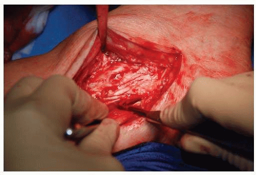 Figure 8.1. The ATFL and the AITFL are sectioned before rotating the fibula and exposing the ankle joint. |
 Figure 8.2. Exposure following fibular osteotomy. The elevator is used to lever the distal fibula and expose the ankle joint. |
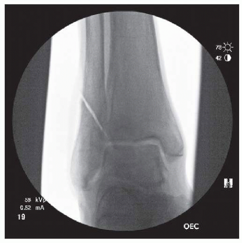 Figure 8.3. Fluoroscopic image after fibular osteotomy. |
MEDIAL-LATERAL SIZING
Use the medial/lateral sizer to assess talar width. Place the sizer between the plafond and the talus such that it abuts the articular portion of the medial malleolus. Fluoroscopy should be used to confirm proper placement (Fig. 8.5). If between sizes, choose the smaller size.
FRAME ASSEMBLY AND ALIGNMENT
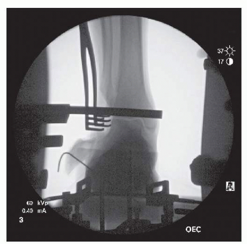 Figure 8.4. Fluoroscopic image showing K-wire fixation of fibula. The probe is resting on the anterior ankle. Its alignment with the ankle joint confirms correct frame assembly and position. |
Place the leg into the alignment stand with the heel in the heel cup. Adjust the heel cup placement so that the lateral ankle view will not be obscured by the alignment rods. Adjust the calf block supports so that the anterior tibial crest is parallel to the longitudinal frame rods. To help determine the proper ankle
rotation, place a straight malleable retractor through the medial incision into the medial gutter. Rotate the leg such that the tibial tubercle is oriented vertically. This should correspond to 5° to 10° of medial angulation of the malleable retractor. To finalize rotation, use the flat end of the joint line tracer probe in the cutting jig and place it against the anterior aspect of the lateral articular body of the talus. If the rotational alignment is correct, the probe end should be flush with or parallel to this anatomic landmark. One other check is to obtain an AP radiograph to see a perfect mortise shot and a lateral radiograph to see collinear arcs of the talus.
rotation, place a straight malleable retractor through the medial incision into the medial gutter. Rotate the leg such that the tibial tubercle is oriented vertically. This should correspond to 5° to 10° of medial angulation of the malleable retractor. To finalize rotation, use the flat end of the joint line tracer probe in the cutting jig and place it against the anterior aspect of the lateral articular body of the talus. If the rotational alignment is correct, the probe end should be flush with or parallel to this anatomic landmark. One other check is to obtain an AP radiograph to see a perfect mortise shot and a lateral radiograph to see collinear arcs of the talus.
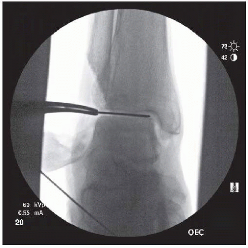 Figure 8.5. Fluoroscopy is used to confirm correct sizer placement. |
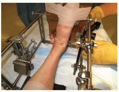 Figure 8.6. The foot is secured to the foot plate with an elastic bandage. |
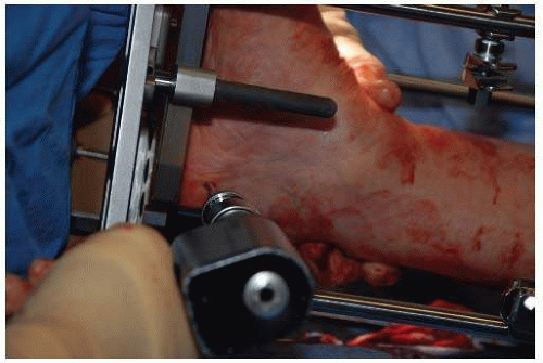 Figure 8.7. Image shows medial-to-lateral placement of the calcaneal transfixion pin. |
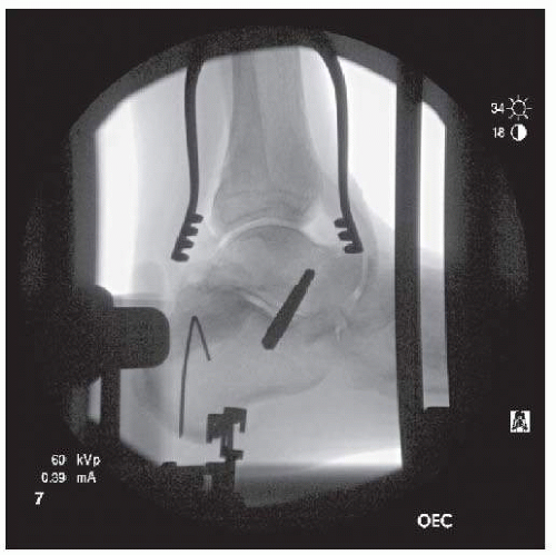 Figure 8.8. Flouroscopic image shows correct talar pin placement. |
Attach foot plate brackets at the level of the metatarsophalangeal joints. Secure the foot to the plate by running an elastic bandage through the foot plate brackets (Fig. 8.6). Do not allow the foot brackets to compress the foot and create a pressure point. Use the tibial alignment rod visually and radiographically to determine the axial alignment of the limb in the coronal plane. Place a calcaneal transfixion pin from medial to lateral (Fig. 8.7). Ideal placement is 2.5 cm anterior to the insertion of the Achilles tendon, avoiding injury to medial structures. Attach the calcaneal transfixion pin to the foot plate using pin hooks. Tighten the hooks symmetrically such that pin bends slightly and then remove heel support cup.
Related posts:
 Walking Mechanics Following Surgical Interventions for Ankle Arthritis
Patient Selection, Surgical Indications, and Preoperative Planning
Management of Anterior Translation of the Talus During a Total Ankle Replacement
Complications After Total Ankle Replacement
Polyethylene
Conversion of Painful Ankle Arthrodesis to Total Ankle Replacement
Walking Mechanics Following Surgical Interventions for Ankle Arthritis
Patient Selection, Surgical Indications, and Preoperative Planning
Management of Anterior Translation of the Talus During a Total Ankle Replacement
Complications After Total Ankle Replacement
Polyethylene
Conversion of Painful Ankle Arthrodesis to Total Ankle Replacement
Stay updated, free articles. Join our Telegram channel

Full access? Get Clinical Tree


