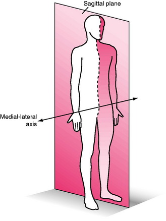
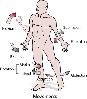
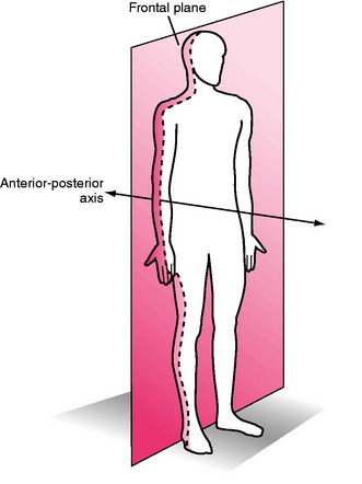
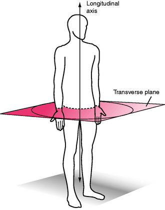
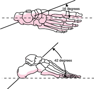
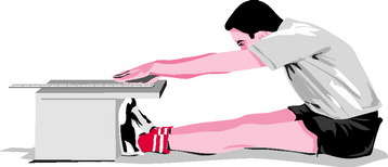
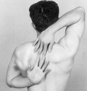
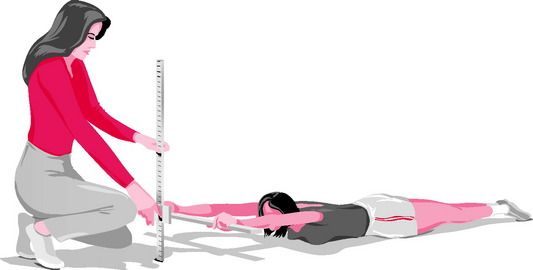
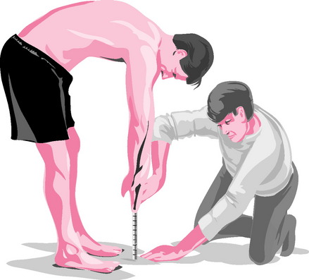
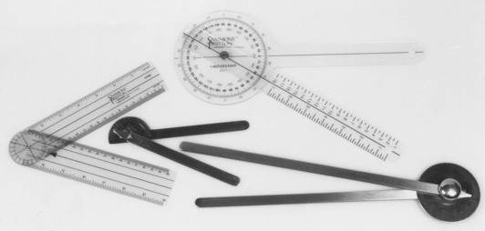
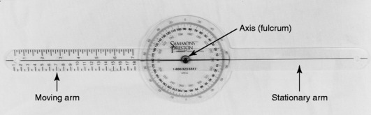
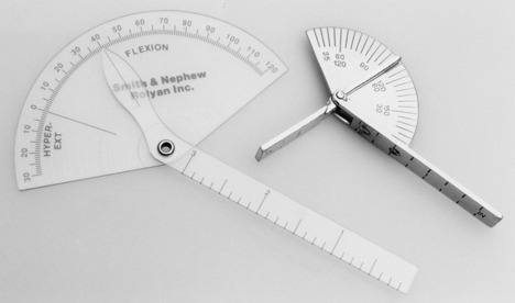
Chapter 1 Historically, early reports on procedures for the examination of range of motion (ROM) suggested using visual approximation27. In fact, as late as the 1960s, the initial edition (1965) of a text for measuring joint ROM published by the American Academy of Orthopaedic Surgeons (AAOS)3 suggested that visual estimation is as good as, or better than, goniometric measurement. This opinion was shared by Rowe,95 who suggested that visual estimation was especially important when bony landmarks were difficult to see or to palpate. In contrast, Moore78 and Salter98 stated that goniometer measurements are more reliable than visual estimates. Disagreement exists among studies that have objectively examined the value of visual estimation compared with the goniometer. Studies by both Awan et al8 and Hayes et al55 reported that little difference existed between visual inspection and a goniometer for the measurement of shoulder ROM. However, upon further examination of the reliability coefficients, intrarater reliability ranged from .59 to .71 for visual inspection and from .53 to .71 for the use of the goniometer. In other words, the testers who collected the data were not all that accurate, irrespective of whether or not a goniometer was used. Williams and Callaghan115 also reported that no significant difference existed between visual estimation and the goniometer in the measurement of shoulder flexion. However, the design of this study, in which three testers measured one subject twice while the subject held the arm elevated, calls into question the rigor of this investigation. In contrast, Watkins et a1111 reported that reliability of the measurement of knee flexion was greater when a goniometer rather than visual estimation was used. Additionally, two studies in which the lead author was Youdas119,120 reported that the use of instruments to examine the ankle and the cervical spine resulted in more accurate measurements than were obtained through visual estimation. Given the research suggesting that objective measurement is more accurate than visual examination for the measurement of joint ROM, and the fact that scientists, the government, and the public demand improved outcomes in terms of patient intervention, accurate and standardized measurements are of utmost importance. Joint ROM is an integral part of human movement. In order for an individual to move efficiently and with minimal effort, full ROM across the joints is imperative. In addition, appropriate ROM allows the joints to adapt more easily to stresses imposed on the body and decreases the potential for injury. Full ROM across a joint is dependent on two components: joint ROM and muscle length.121 Joint ROM, the motion available at any single joint, is influenced by associated bony structure and physiologic characteristics of the connective tissue surrounding the joint. Important connective tissue that limits joint ROM includes ligaments and joint capsules.42 Muscle length refers to the ability of a muscle crossing the joint to lengthen, allowing one joint or a series of joints to move through the available ROM. The terms muscle length and flexibility often are used synonymously to describe the ability of a muscle to be lengthened to the end of the ROM. In this book, the term muscle length is used to refer to the end of the range of the muscle across the joint.121 According to Kendall et al,65 “For muscles that pass over one joint only, the range of motion and range of muscle length will measure the same …. For muscles that pass over two or more joints, the normal range of muscle length will be less than the total range of motion of the joints over which the muscle passes.” Therefore, if the goal is to measure joint ROM of a joint in which a two-joint muscle is involved, the second joint should be placed in a shortened position. If the goal is to measure muscle length, the muscle should be placed in an elongated position across all joints affected, and a measurement should be taken.65 An example that illustrates the difference between ROM and range of muscle length is the measurement of knee flexion. To measure knee flexion joint motion, the hip should be flexed (the patient is supine) to put the rectus femoris muscle in a shortened position, and to allow full joint motion at the knee (illustrated in Chapter 12, Figs. 12-8 through 12-11). When muscle length of the rectus femoris muscle (a two-joint muscle) is measured, the patient is placed in the prone position, which extends the hip and lengthens the rectus femoris muscle (described in Chapter 14, Figs. 14-13 through 14-15). Neumann82 defines kinematics as “a branch of mechanics that describes the motion of a body without regard to the forces or torques that may produce the motion.” In other words, kinematics describes human movement and ignores the cause of the motion (e.g., forces, momentum, energy). This description of motion may include movement of the center of gravity of the body or movement of the extremities, or it may pertain to motion specific to one joint. Kinematics can be subcategorized into specific movements, referred to as arthrokinematics and osteokinematics. To more fully understand kinematics as it relates to measurement of range of joint motion and muscle length, clarification of the terms arthrokinematics and osteokinematics is necessary. Arthrokinematics refers to actual movements of the joint surfaces in relation to one another. In addition to movement of the lever arm of the bone during ROM activities, the articulating ends of the bone roll, slide (or glide), or spin on each other. Roll is a rotary motion that occurs when new points on one joint surface come in contact with new points on a second joint surface. Slide is a translatory motion that occurs when one joint surface glides across a second surface, so that the same point on one surface is continually in contact with new points on the second surface. A rolling surface usually occurs with a concurrent, oppositely directed slide. Spinning occurs during joint rotation when the longitudinal axis of long bones interacts at a right angle to the articular joint surface. An example is medial and lateral rotation of the shoulder joint when the humerus is abducted to 90 degrees.82 Although arthrokinematic motion is vital for normal ROM, this textbook does not address the measurement or grading of this type of motion. The quality and degree of motion actually observed in the bony lever arm is called osteokinematic motion. Osteokinematic motion is movement of the whole bone that results from rolling and sliding (arthrokinematics) between the articulating surfaces that compose the joint measured.82 For example, when the arm is raised overhead, the bony lever arm (the humerus) moving overhead is the osteokinematic motion. However, for this motion to occur, the head of the humerus must roll and slide on the glenoid fossa (arthrokinematic motion). In most cases, osteokinematic motion is the actual motion that is measured; this type of motion is the focus of this textbook. Osteokinematic descriptions of movement follow a generalized system that is based on definitions of planes of movement around axes of rotation. For effective discussion of planes of motion and axes of movement, a reference point is required, a point referred to as the anatomical position. This reference point (anatomical position) is defined as “standing erect with the head, toes, and palms of the hands facing forward and with the fingers extended.”104 When ROM at a joint is measured, the starting position is typically the anatomical position. Figures 1-1 through 1-4 all show the model standing in the anatomical position. Osteokinematic movement may be described as occurring in one of three imaginary planes of the body, arranged perpendicular to each other, with the axes of each plane intersecting the center of gravity of the body. These imaginary planes are referred to as the cardinal planes of the body. It should be emphasized that human motion is not limited to movement in these cardinal planes, but that this system of planes of movement around axes of rotation provides a simple method for describing ROM and muscle length.82 The sagittal plane is a vertical plane that divides the body into right and left sides (Fig. 1-1). Photographically, this is a side view. Joint movement in the sagittal plane occurs around a line perpendicular to the plane that is referred to as the medial-lateral axis. The osteokinematic motions that occur in the sagittal plane are flexion and extension (Fig. 1-2).82 Gray’s Anatomy defines flexion as occurring “when the angle between two bones is decreased.”26 In other words, during flexion, two bony levers move around the joint axis so that the two levers approach each other. Flexion at the ankle is given a special term, with approximation of the plantar surface of the foot and the leg in the sagittal plane referred to as plantarflexion. Extension is the opposite of flexion. It occurs when the two bony levers move away from each other, and it is defined as “the act of straightening a limb,” which “occurs when the angle between the bones is increased.”26 Hyperextension is defined as extension beyond the normal anatomical ROM. Dorsiflexion of the foot at the ankle in the sagittal plane is the opposite of plantarflexion. The frontal (or coronal) plane is a vertical plane that divides the body into anterior (ventral, or front) and posterior (dorsal, or back) halves (Fig. 1-3). Photographically, this is a front view. Joint movement in the frontal plane occurs around a line perpendicular to the plane that is referred to as the anterior-posterior axis. The osteokinematic motions that occur in the frontal plane consist of abduction, adduction, and lateral flexion of the spine (see Fig. 1-2).82 Abduction is defined as occurring “when a limb is moved away from the midsagittal plane, or when the fingers or toes are moved away from the median longitudinal axis of the hand or foot.”26 Abduction of the wrist is often referred to as radial deviation. The median longitudinal axis of the hand is the third metacarpal, and for the foot, this axis is the second metatarsal. An exception to this definition is abduction that takes place at the carpometacarpal (CMC) joint of the thumb, which is defined as “that action by which the thumb is elevated anterior to the palm.”26 Therefore, abduction at the CMC joint actually takes place in the sagittal plane. Adduction is the opposite of abduction, and “occurs when a limb is moved toward or beyond the midsagittal plane, or when the fingers or toes are moved toward the median longitudinal axis of the hand or foot.”26 Adduction of the wrist is often referred to as ulnar deviation. At the CMC joint of the thumb, adduction is moving the thumb posteriorly toward the palm (sagittal plane movement). The transverse plane is a horizontal plane that divides the body into upper (superior, or cranial) and lower (inferior, or caudal) halves (Fig. 1-4). Photographically, this is a view from the top of the head. Joint movement in the transverse plane occurs around a line perpendicular to the plane (a line running from cranial to caudal) that is referred to as the longitudinal (or long) axis. The osteokinematic motions that occur in the transverse plane include medial rotation, lateral rotation, pronation, and supination (see Fig. 1-2).82 Rotation “is a form of movement in which a bone moves around a central axis without undergoing any other displacement.”26 Medial (or internal) rotation refers to rotation toward the body’s midline, and lateral (or external) rotation refers to rotation away from the body’s midline. Pronation is defined as medial rotation of the forearm that occurs when the segment is turned in a way that causes the palm of the hand to face posteriorly (in relation to anatomical position). Supination is lateral rotation of the forearm that occurs when the segment is turned so that the palm of the hand faces anteriorly (related to anatomical position). Motions that occur at the talocrural, subtalar, and midtarsal joints do not take place around the previously described cardinal axes. Contemporary explanations describe motion at these joints as occurring around oblique axes that lie at angles to all three cardinal planes.31,82,93 These so-called triplanar axes run in an anteromedial-to-posterolateral direction and allow motion in all three planes simultaneously (Fig. 1-5). The motions thus produced have been termed pronation (a combination of dorsiflexion, abduction, and eversion) and supination (a combination of plantarflexion, adduction, and inversion).31,82,93 The inspiration for the universal goniometer appears to have been devices used to measure ROM that were developed in France early in the 1900s.102 Initial publications describing the use of goniometers apparently are contained in the French medical literature, and descriptions of goniometric use did not appear in the American or British literature until the second decade of the 20th century.43,46 With the advent of each of the World Wars came an increased interest in, and use of, the goniometer.78 Although many variations and specialized designs of the goniometer have been developed over the years,* today’s universal goniometer remains little changed from the instrument described by Clark24 in 1920. The universal goniometer has been used frequently for measurement of joints of the upper extremity,35,63 lower extremity,1,76 and spine.19,84,87,120 Although reliable goniometers were available for measuring joint ROM early in the 20th century, examiners did not agree on correct procedures for performing goniometric measurements. In 1920, Clark24 attempted to alleviate this problem by providing some standards for examining and recording joint ROM using the universal goniometer. He described a standardized starting position for measurement that was identical to the anatomical position currently used, with the exception of the position of the ankle, which Clark24 described as fully plantarflexed. Additionally, Clark24 provided values for normal ROM of joints of the spine and extremities, although the source and method of measurement on which these values were based were not stated. However, no description of techniques for patient positioning and goniometer placement was included in Clark’s recommendations.24 Numerous other individuals and groups have proposed methods for measuring and recording joint ROM using the universal goniometer.† The most widely accepted techniques appear to be those published by the AAOS,3,49 which were based on work done by Cave and Roberts.20 These techniques, which are cited more often than the techniques of any other group in studies involving measurement of ROM, were developed by a committee of the AAOS in the early 1960s. The pamphlet containing the original techniques was sent to members of the AAOS in 1961, and subsequently to orthopaedic societies in Australia, Great Britain, Canada, New Zealand, and South Africa. Following multiple revisions, the techniques were published in booklet form by the AAOS in 19653 and gained the approval of orthopaedic societies in all countries to which the original pamphlet was sent. The most recent version of the AAOS techniques was published by Greene and Heckman in 1994.49 Although the AAOS techniques49 provide illustrations to aid in the measurement of ROM, specific landmarks for alignment of the goniometer during measurement are not provided. Instructions consist primarily of line drawings of a subject in what is termed the “zero starting position,” with limits of normal ROM indicated in some but not all cases. These norms are based, for the most part, on studies of adults, with small sample sizes and no accompanying reliability data. The reliability of techniques used to measure joint motion is not discussed. Efforts have been made, and continue to be made, to refine the techniques of goniometry used to measure ROM of the joints. Several groups of investigators have examined the reliability of currently used techniques (see Chapters 7, 10, and 15), and, in some cases, recommendations have been made as to preferred techniques for measuring a particular joint motion, based on reliability studies. However, the most reliable techniques for measuring motion at most joints in the body are yet to be determined, and much additional work remains to be done in this area. Currently, the most widely accepted method of recording ROM information is based on a system of measurement known as the 0–180 system. This system defines the anatomical position as the 0-degree starting position of all joints except the forearm, which is fully supinated. Thus, neutral extension at each joint is recorded as 0 degrees, and as the joint flexes, motion progresses toward 180 degrees. The 0–180 system, which was first described by Silver100 in 1923, has been endorsed by the AAOS49 and the American Medical Association (AMA),3 as well as in the physical therapy literature.78 Descriptions of how to document ROM using the 0–180 method are provided later in this chapter. Other measurement systems have been used as a basis for recording ROM, but these methods are rarely used today. In 1920, Clark24 described a system for recording ROM that was based on the idea that neutral extension at each joint is recorded as 180 degrees, movement toward flexion approaches 0 degrees, and movement toward extension past neutral also approaches 0 degrees.24 According to this 180–0 system, the shoulder position that would be indicated as 145 degrees flexion according to the 0–180 system would be designated as 35 degrees flexion in the 180–0 system. A second system that has been used in the past but is not in common use today is based on a full 360-degree circle, in which the 0-degree position of each joint is full flexion, neutral extension is recorded as 180 degrees, and motions toward extension past neutral approach 360 degrees.80,113 Although the universal goniometer remains the most widely used instrument in the measurement of joint motion, limitations in the application of this device to some joints have led to the development of specialized devices for measuring joint motion. Most of these devices are designed to measure motion at only one joint, or at most a few joints, although some are capable of more widespread application. Examples of highly specialized devices for measuring joint ROM include Therabite (Atos Medical AB, Hörby, Sweden), for measuring motion of the temporomandibular joint (see Figs. 9-67 and 9-68 for a description of its use), and specialized devices for measuring motion of the shoulder,2,94 forearm,6,25,30,57 wrist,30,57 hand,36,52,85,105 hip,39,51,94 knee,39 and foot and ankle.* Some of the more specialized devices used to measure joint ROM are adaptable for measuring motion at several joints. Examples of such devices include the inclinometer (also called the bubble goniometer, the pendulum goniometer, and the gravity goniometer) and the electrogoniometer, as well as various types of radiographic, photographic, and video recording equipment, including highly sophisticated motion analysis systems.77,109 Of these specialized devices, the inclinometer is probably the most widely used because of its portability and relatively low cost. In the early 1930s, Fox and van Breeman44 reported that they measured ROM using an instrument called the pendulum goniometer, which consisted of a circular scale, “to the center of which is attached a weighted pointer at one end so that it remains vertical while the scale rotates around it.” Early studies reported use of a pendulum goniometer to measure ROM of the upper and lower extremities.47,53,78 In 1955, Leighton69 introduced a similar instrument, referred to as the “Leighton flexometer,” which consisted of a 360-degree dial and a weighted pointer mounted in a case. The dial and pointer operated freely, with movement controlled by gravity. The device was strapped to the segment being measured, the dial was locked at the extreme of motion, and the arc of movement was registered by the pointer. Leighton’s study69 was one of the first to use the device to attempt to provide normative data on ROM and muscle length in 30 joints of the extremities and trunk in a group of 16-year-old males. More recently, Ekstrand et a134 used a modification of the Leighton flexometer to measure ROM of the hip, knee, and ankle. Schenker99 introduced the fluid goniometer (bubble goniometer) in 1956. The fluid goniometer contains a 360-degree scale with a fluid-filled circular tube containing a small air bubble. Strapping the device to the segment being measured and moving the segment causes the scale to rotate while the bubble remains stationary, thereby indicating the ROM in the scale. The fluid goniometer has been used to measure the shoulder,23 knee,90 elbow,86 ankle,75 and cervical spine.11 Loebl70 was the first to use the term inclinometer to describe the wide range of measuring instruments that rely on the principle of gravity. In general, these instruments are calibrated or referenced on the basis of gravity, with a starting zero position that is indicated by a fluid level or, more commonly, a weighted needle. Today, the term inclinometer refers to devices labeled for how the instrument works (gravity goniometer, bubble goniometer), as well as for the manufacturer that developed the measurement tool (Myrin goniometer [LIC Reha Care, Sweden], Rangiometer [Maker, Inc.], CROM [Performance Attainment Associates, Roseville, Minn.], BROM [Performance Attainment Performance, Roseville, Minn.]).42,61,67,68,117 Electrogoniometers, which convert angular motion of the joint into an electric signal, first appeared in the 1950s.62 The basic principle of this type of goniometer has been modified to produce a variety of styles of electrogoniometer that are currently in use. Some electrogoniometers are designed to measure motion at a single joint, such as the elbow79 or the hip,37 whereas others are designed to measure motion at a variety of joints.6,22,48,83 Designs range from fairly cumbersome devices to more compact, portable systems. Although many electrogoniometers are capable of measuring motion in several planes simultaneously, the cost of these devices and the skill required for application have caused electrogoniometers to be used primarily in research applications. Still photography has been used to measure joint ROM for decades116,122 and remains in use today.13,39,55 Although still photography has been reported to be more accurate than standard methods of goniometry in measuring ROM of the elbow joint40 and shoulder,55 measuring ROM with the use of still photography requires more time and effort than is practical in a normal clinical situation. Video recording techniques also have been used to measure joint ROM.* Although many motion analysis systems are commercially available, the examination of joint ROM using video recording equipment, such as motion analysis systems, remains generally confined to the research arena because of the prohibitive cost and decreased portability of such equipment. The gold standard against which all other techniques of measuring joint ROM are compared is radiographic measurement of joint motion. Radiographic techniques have been used to study the amount and type of motion that is occurring at various joints, as well as to examine the validity of goniometry.* However, the routine use of radiographic techniques for the measurement of joint motion is not recommended because of the health risks associated with repeated exposure to radiation and because of the high costs involved. A review of the literature indicates that muscle length is measured primarily through two methods. The first method uses traditional composite tests, which consist of measuring movement across more than one muscle or more than one joint.54 Frequently used composite tests include the sit-and-reach test (Fig. 1-6), Apley’s scratch test (Fig. 1-7), the shoulder-lift test (Fig. 1-8), and the fingertip-to-floor test (Fig. 1-9). The second method is direct measurement of muscle length, in which excursion between adjacent segments of one joint is involved.58 Examination of muscle length originated in the physical education literature and can be traced back to the 1940s, when a large number of veterans returned from World War II with limited movement capabilities.10 Following World War II, great emphasis was placed on physical fitness testing, with flexibility being one component that was measured. In 1941, Cureton28 published a “14-Item Motor Fitness Test” that contained four measures of flexibility. These flexibility measurements consisted of composite tests involving flexion and extension of the entire length of the body. Interest in the importance of examining muscle length was heightened when Kraus66 reported that lack of flexibility and lack of strength were major factors in the high incidence of back pain in the United States. Testing by Kraus,66 who used strength testing and composite flexibility tests, indicated that American children were minimally fit and significantly less fit than European children, leading to the further increase in the use of fitness testing. Fleischman41 used six fitness tests to perform a factor analytic study that concluded that flexibility was “one of the important parts of overall fitness.” In the 1970s, the American Alliance for Health, Physical Education, Recreation, and Dance (AAHPERD) built on the work of these fitness pioneers and developed language to describe health-related physical fitness. Health-related physical fitness consists of qualities that “have been formed to contribute to one’s general health by reducing the risk of cardiovascular disease, problems associated with obesity, and chronic back problems.”10 Health-related fitness consists of five categories that should be examined: aerobic endurance, muscular endurance, muscular strength, body composition, and flexibility. The AAHPERD developed a standardized health-related fitness test battery, referred to as the “Physical Best Assessment Program.” Included in this program is the composite flexibility test, referred to as the sit-and-reach test (described later in this text in Chapter 8).10 The American College of Sports Medicine4 recommends a flexibility exam consisting of the “sit-and-reach test or goniometer measurements of isolated joints” as part of a suggested comprehensive health fitness evaluation. Not only is flexibility one of the five specific components of health-related physical fitness defined by the AAHPERD, but research indicates that flexibility is highly specific to each muscle involved. It does not exist as a general characteristic but is specific to the joint and muscle in question.15,54,58 This research has shown that it is possible to have ideal muscle length in one muscle crossing a joint and poor flexibility at another joint in the body. Harris54 suggested that “there is no evidence that flexibility exists as a single general characteristic of the human body. Thus, no one composite test can give a satisfactory index of the flexibility characteristics of an individual.” Hubley-Kozey58 suggested that composite tests do not provide accurate measurements of flexibility because these tests assess combinations of movements across several joints and involving several muscles. The author continues by indicating that composite tests are of questionable accuracy owing to difficulty in determining which muscles actually are being examined and to the complexity of the movement. In conclusion, Hubley-Kozey58 suggests that composite tests “serve as gross approximations for flexibility, at best.” On the basis of information provided by authors such as Harris54 and Hubley-Kozey,58 composite measurement does not appear to be the appropriate measurement technique for muscle length. Therefore, in this text, every effort is made to provide only direct measurement of flexibility in describing techniques for upper (see Chapter 6) and lower (see Chapter 14) extremity muscle length testing. The universal goniometer is produced in a variety of forms and sizes (Fig. 1-10). Most commonly, the universal goniometer is made of either metal or clear plastic and consists of a central protractor portion on which are mounted two arms of varying lengths. The protractor portion of the goniometer may be either a full circle or a half circle, both of which are calibrated in degrees. Although the scales of some goniometers are marked in gradations of 2.5 or 5 degrees, for optimal accuracy, the scale should be marked at 1-degree intervals. Many goniometers are marked with a line that runs from the 0-degree to the 180-degree mark on the protractor. This line represents the base line of the protractor and serves as a reference point for measurements. One of the two arms of the goniometer is an extension of the protractor (the stationary arm); the other arm is riveted to, and can move independently of, the protractor (the moving arm) (Fig. 1-11). The central rivet, which attaches the moving arm to the protractor, functions as the axis, or fulcrum, of the goniometer. If the goniometer is made of metal, the end of the moving arm that is in contact with the protractor (the proximal end) should be tapered to a point on its end or should contain a cutout so that the degree indicators on the protractor scale can be viewed (see Fig. 1-10). This concern is not relevant with a plastic goniometer because the scale can be viewed easily through the plastic arm. The arms of a plastic goniometer generally are calibrated along their length in centimeters or inches, for convenience when linear measurements are needed. Additionally, a prominent line extends from the axis of the goniometer down the midline of each arm, providing a landmark on the goniometer that can be maintained in line with bony landmarks on the body during goniometric measurements (see Fig. 1-11). Many modifications of the basic design for the universal goniometer exist. One of the most common, and one that is used in this text, is the finger goniometer. The finger goniometer is basically a scaled-down version of the universal goniometer, with some modifications so that it fits the finger joints more precisely (Fig. 1-12). The finger goniometer is designed to be used over the dorsum of the finger joints, and many styles have broad arms that lie flat against the dorsal surfaces of the metacarpals or phalanges when the goniometer is in place. Some styles of finger goniometer are limited as to the amount of extension that can be measured because of a physical block built into the goniometer at 30 degrees of extension. FURTHER EXPLORATION: FAMILIARIZATION WITH THE UNIVERSAL GONIOMETER: The activities in Box 1-1 are designed to help the reader become familiar with a goniometer and attain proficiency in manipulating the device and reading the scale correctly. Select a goniometer and locate the parts and features listed in Box 1-1. Make sure several different styles of goniometers are examined and the features of each are compared. Box 1-1 Features of the Goniometer (see Fig. 1-11) 1. Is the protractor a half or a full circle? 2. Is the protractor marked in 1-, 2.5-, or 5-degree increments? 3. Is a single scale marked on the protractor, or is more than one scale present? 4. If more than one scale is present, are the scales marked in the same direction, or in opposite directions? 5. Locate the base line of the protractor (line extending between the 0-degree mark and the 180-degree mark). The base line is the reference from which measurements are made.
MEASUREMENT of RANGE of MOTION and MUSCLE LENGTH
BACKGROUND, HISTORY, and BASIC PRINCIPLES
JOINT RANGE OF MOTION VERSUS MUSCLE LENGTH
KINEMATICS
Arthrokinematics
Osteokinematics
Sagittal Plane
Frontal Plane
Transverse Plane
Special Case: Oblique Axis at the Foot and Ankle
HISTORY OF INSTRUMENTS USED TO MEASURE RANGE OF MOTION AND MUSCLE LENGTH
Measurement Techniques
Methods of Documentation
Other Measurement Devices
Inclinometer
Electrogoniometer
Photography and Video Recording Equipment
Radiographic Equipment
MEASUREMENT METHODS OF MUSCLE LENGTH
Composite Method
Direct Measurement
PROCEDURES FOR MEASUREMENT
Universal Goniometer
Related posts:
 RELIABILITY and VALIDITY of MEASUREMENTS of RANGE of MOTION and MUSCLE LENGTH TESTING of the UPPER EXTREMITY
MEASUREMENT of RANGE of MOTION and MUSCLE LENGTH: CLINICAL RELEVANCE
MEASUREMENT of RANGE of MOTION of the KNEE
MEASUREMENT of RANGE of MOTION of the HIP
MEASUREMENT of RANGE of MOTION of the ANKLE and FOOT
PEDIATRIC RANGE of MOTION
RELIABILITY and VALIDITY of MEASUREMENTS of RANGE of MOTION and MUSCLE LENGTH TESTING of the UPPER EXTREMITY
MEASUREMENT of RANGE of MOTION and MUSCLE LENGTH: CLINICAL RELEVANCE
MEASUREMENT of RANGE of MOTION of the KNEE
MEASUREMENT of RANGE of MOTION of the HIP
MEASUREMENT of RANGE of MOTION of the ANKLE and FOOT
PEDIATRIC RANGE of MOTION
![]()
Stay updated, free articles. Join our Telegram channel

Full access? Get Clinical Tree