Fig. 8.1
Inlet view
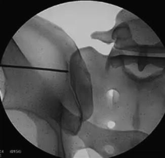
Fig. 8.2
Outlet view
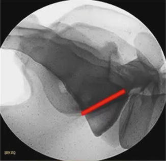
Fig. 8.3
Lateral view
Pelvic Outlet View: This view is a cephalad projection of the sacrum [10]. This view is very important for bringing the neural foramina into view. The X-ray beam is typically perpendicular to the plane of the sacrum with the X-ray beam tilted approximately 25°–35° cephalad (Fig. 8.2).
Lateral View: The lateral view is a “true lateral” view through the sacrum and pelvis. The key to obtaining a true lateral is to wag the C-arm fluoroscope in a direction that results in aligning the sacral alae and iliac notches in the same plane (Fig. 8.3). The true lateral view helps define the “safe zones” for hardware placement during the lateral approach (Fig. 8.4).
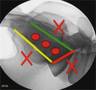
Fig. 8.4
Safe zones delineated on a lateral view
Hardware should be placed within the sacrum with care to not breach the anterior sacral wall. Placement should not be too posterior within the sacrum to avoid entering the sacral canal. Also, the purchase is reduced with posteriorly placed hardware. There are several ligamentous structures along the dorsal wall of the sacrum, and placement among these structures would decrease the strength of the instrumentation. In addition, all hardware should be placed caudal to the sacral alae to maximize hardware purchase. This “safe zone” is outlined in Fig. 8.5.
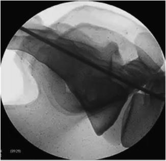
Fig. 8.5
Posterior wall, sacrum
Pelvic Inlet View: This view is the least utilized view in this surgical procedure. It is typically used to make sure that the hardware placed in the pelvis and sacrum does not breach the anterior sacral wall and enter the pelvis [10]. The fluoroscope is positioned for an AP view of the sacrum with the X-ray beam tilted approximately 25° caudally (Fig. 8.1).
Step 3: Skin Marking
Using the lateral view, the margins of the posterior wall of the sacrum and the sacral alae are outlined on the skin of the ipsilateral buttock using a marker (Figs. 8.6 and 8.7). A 3 cm incision is marked on the skin approximately 1–2 cm dorsal to the posterior sacral wall line.
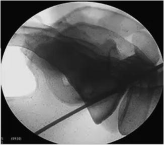
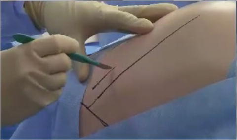
Fig. 8.6
Sacral ala
Fig. 8.7
Skin marking, 3 cm incision
Step 4: Guide Wire Placement
The skin is incised sharply. The guide wire is inserted into the incision with its tip on the cortical wall of the ilium. The ideal insertion point is then determined utilizing the lateral fluoroscopic view. The ideal starting point is 0.5–1 cm ventral to the posterior sacral wall and 1 cm caudal to the sacral alar line (Fig. 8.8).
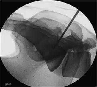
Fig. 8.8
Lateral view, initial placement and trajectory
The pelvic outlet view is then used to confirm that the trajectory of the guide wire crosses the SIJ and respects the neural foramina (Fig. 8.9).
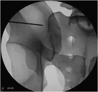
Fig. 8.9
Pelvic outlet view, initial pin placement and trajectory
Once these two views have confirmed a safe trajectory for the guide wire, the guide wire is either tapped or drilled across the SIJ (Fig. 8.10).
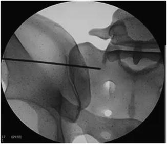
Fig. 8.10
Initial pin, final placement
Please refer to Fig. 8.4 to see the “safe zone.” The guide wires should be positioned such that they are all at least 1–2 mm lateral to the lateral border of the neural foramina in order to avoid injury to the neural elements (Fig. 8.10). Some surgeons may elect to place the screws that are just cephalad and caudal to the first sacral foramen deeper into the sacrum to obtain more bony purchase. We do not currently do this at our institution, as we have obtained adequate purchase with the shorter screws.
Step 5: Tubular Retractor Placement
Sequential dilators are placed over the guide wire. Following the last sequential dilation, the tubular retractor is inserted. This will serve as the working channel for the procedure (Fig. 8.11).
 Round-Table Discussion, April 2, 2014
Biomechanics of the Injured SIJ: Results from an In Vitro Study
Postsurgical Rehabilitation
Posterior Lateral Open Approach for Sacroiliac Joint Arthrodesis
Posterior Lateral into the Longitudinal Joint Axis Approach: Minimally Invasive
Posterior Inferior Approach, Minimally Invasive
Round-Table Discussion, April 2, 2014
Biomechanics of the Injured SIJ: Results from an In Vitro Study
Postsurgical Rehabilitation
Posterior Lateral Open Approach for Sacroiliac Joint Arthrodesis
Posterior Lateral into the Longitudinal Joint Axis Approach: Minimally Invasive
Posterior Inferior Approach, Minimally Invasive


Related posts:
Round-Table Discussion, April 2, 2014
Biomechanics of the Injured SIJ: Results from an In Vitro Study
Postsurgical Rehabilitation
Posterior Lateral Open Approach for Sacroiliac Joint Arthrodesis
Posterior Lateral into the Longitudinal Joint Axis Approach: Minimally Invasive
Posterior Inferior Approach, Minimally Invasive
Stay updated, free articles. Join our Telegram channel
Full access? Get Clinical Tree
