Chapter 121 Kinematic Alignment in Total Knee Arthroplasty
Kinematic alignment can prevent the loss of flexion and extension, stiffness, instability, pain, and prolonged recovery associated with mechanical alignment.16,17 Kinematic alignment of the femoral component is confirmed intraoperatively by comparing the symmetry of the thickness of the distal medial, distal lateral, posterior medial, and posterior lateral femoral bone resections after measuring the thickness of the resections with calipers and after correcting for cartilage wear, bone wear, and kerf (i.e., the bone removed by the saw blade). Once kinematic alignment of the femoral component is confirmed, restoring motion and balancing the total knee arthroplasty is simplified by following a stepwise algorithm. The algorithm consists of four steps—removing osteophytes, adjusting the plane of the tibial cut, releasing the posterior capsule from the femur, and medializing or lateralizing the tibial component.
History and Definition of Kinematic Alignment
The biomechanical rationale for kinematic alignment is traced to Hollister and colleagues’ classic research on the kinematics of the knee.12 Kinematics refers to the relative relationship of the femur, patella, and tibia at any angle of flexion, without force applied to the knee. The joint surface, menisci, and ligament structures determine the normal kinematic relationship among the femur, patella, and tibia. The center of the femoral head and center of the ankle, which are used by conventional and computer-assisted instruments to align a TKA mechanically, have no bearing on the kinematics of the knee.10,11,14,15
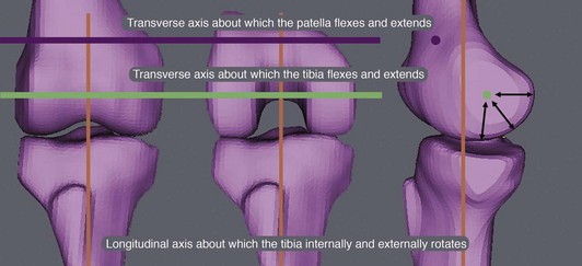
Three axes govern the movement of the patella and tibia with respect to the femur, and understanding how the placement of the femoral and tibial components affects the interrelationship of these axes is the key to kinematically aligning a TKA (Fig. 121-1). The primary axis is a transverse axis in the femur about which the tibia flexes and extends. It passes through the center of a circle fit to the articular surface of the femoral condyles from 10 to 160 degrees of flexion.7,10–12 There is a second transverse axis in the femur about which the patella flexes and extends that is parallel, proximal, and anterior to the transverse axis in the femur about which the tibia flexes and extends. The third axis is a longitudinal axis in the tibia about which the tibia internally and externally rotates on the femur that is perpendicular to each of the two transverse axes in the femur. Although each of the three axes is aligned parallel or perpendicular to one another, none are aligned orthogonally to the three anatomic planes, which means that the axis cannot be found with imaging studies performed in the sagittal, coronal, and axial planes.15
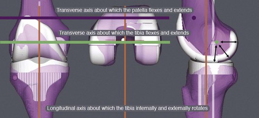
The goal for kinematically aligning the femoral component is to coalign the transverse axis of a symmetrical femoral component with the primary transverse axis in the femur about which the tibia flexes and extends (Fig. 121-2).7,10–12,14 Because there is no clinically important asymmetry between the medial and lateral femoral condyles in the varus and valgus knee with end-stage osteoarthritis, a symmetrical, single-radius femoral component is an optimal design for replicating knee kinematics.
The principle for kinematically aligning the femoral component to the femur is the simple step of shape-matching the femoral component to the articular surface of the femur on a three-dimensional model of the knee that has been restored to normal by filling in the worn articular surface. Shape matching the femoral component to the femur coaligns the transverse axis of the femoral component with the primary transverse axis in the femur about which the tibia flexes and extends, which is requisite to restoring the normal interrelationships among the three axes.13,16
In contrast to the simplicity of kinematically aligning the femoral component, kinematically aligning the tibial component involves several steps. The first step is to align the anterior-posterior axis of the tibial component perpendicular to the transverse axis in the femoral component, which has previously been coaligned to the primary transverse axis in the femur about which the tibia flexes and extends by the shape-matching step.1,7 The second step is to align the tibia to the tibial component kinematically, which is based on the assumption that the internal-external rotational relationship between the femur and tibia is normal in a magnetic resonance imaging (MRI) scan of the non–weight-bearing knee with end-stage osteoarthritis. The assumption that the internal-external rotational relationship is normal in the non–weight-bearing knee with end-stage osteoarthritis is inferred from the layer of joint fluid that is consistently seen separating the worn articular surface between the femur and tibia on the MRI scan of the knee. Both the layer of joint fluid and the image of a non–weight-bearing knee indicate that there is no contact between the worn femur and tibia and no transmission of force across the knee to malrotate the tibia on the femur. The final step is aligning the center of the tibia under the center of the tibial component.
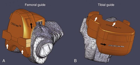
With a goal of improving on the 20% prevalence of patient dissatisfaction from mechanically aligned TKA with conventional and computer-assisted instruments,3,5 we began developing the method for performing kinematic alignment with patient-specific femoral and tibial cutting guides in 2005. We developed software that creates a three-dimensional model of the arthritic knee from a non–weight-bearing MRI or computed tomography (CT) arthrogram of the knee (OtisKnee, OtisMed, Alameda, Calif; http://www.otismed.com). Additional software transforms the arthritic knee model to a normal knee model and then kinematically aligns the components by shape-matching the best-fitting femoral and tibial components to the normal knee model. The three-dimensional position of each component is then transferred from the normal knee to the arthritic knee model. Patient-specific cutting guides that incorporate the cut planes of each component and that reference the arthritic knee model are made to fit the patient’s femur and tibia (Fig. 121-3). The cutting guides are used intraoperatively to transfer the six degrees of freedom (6DOF) positions of the femoral and tibial components from the computer to the patient—varus-valgus, internal-external rotation, flexion-extension, anterior-posterior, proximal-distal, and medial-lateral.13,14,16,25
Advantages of Kinematic Alignment Over Mechanical Alignment
Studies from the United Kingdom and Canada that reviewed more than 10,000 patients at 1 year following mechanically aligned TKA with conventional instruments and contemporary components have shown that one of five patients are not satisfied because of continued pain and poor function in activities of daily living (ADLs).3,5 The use of computer-assisted surgery has improved the mechanical alignment compared with conventional surgery, but has not improved the clinical outcome (much to the dismay of proponents of computer-assisted surgery).2,9,21,26 Therefore, a mechanically aligned TKA, whether performed with conventional instruments or computer assistance, has an unacceptably high prevalence of continued pain, poor function in ADLs, and patient dissatisfaction, which means that there is ample room for improvement.
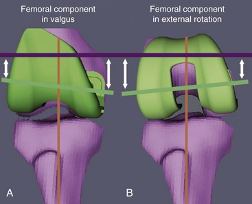
For the kinematics of a TKA to be the same as a normal knee, the three-dimensional placements of the femoral and tibial components have to be chosen so that the orientation of the three kinematic axes is unchanged from that of the normal knee. None of these axes can be found by referencing the transepicondylar axis, center of the femoral head, and center of the ankle with the use of conventional or computer-assisted instruments.1,10,15 There is a 5-degree average difference (range, 2 to 11 degrees) between the transepicondylar and primary transverse axes in the femur about which the tibia flexes and extends, which means that referencing the transepicondylar axis substantially changes the joint line from normal in the axial plane.11 Of normal subjects, 98% do not have a neutral hip-knee-ankle axis because the longitudinal shape of the femur and tibia are unrelated and variable among subjects, which means that referencing the center of the femoral head and of the ankle changes the joint line in the coronal plane.12 Changing the joint line of the femur from normal in the axial and/or coronal planes using instruments that align components to the transepicondylar axis, center of the femoral head, and center of the ankle kinematically malalign the knee and may explain the midrange instability reported in TKA (Fig. 121-4).7 Because mechanical alignment kinematically malaligns the knee, we hypothesized that kinematic alignment would reduce the high prevalence of persistent pain, poor function in ADLs, and patient dissatisfaction after mechanically aligned TKA with conventional and computer-assisted instruments.16,25
Planning Kinematic Alignment With Patient-Specific Cutting Guides
Protocol for Aligning and Performing Magnetic Resonance Imaging of the Knee
The following is a description of the suggested MRI technique, which relies on the use of coronal and axial locator images to obtain nonorthogonal, oblique, sagittal images perpendicular to the primary transverse axis in the femur about which the tibia flexes and extends (Fig. 121-5).14 A nonorthogonal, oblique, sagittal MRI scan of the treated knee is obtained using a 1.5- or 3.0-T scanner and dedicated knee coil. The plane for the nonorthogonal, oblique, sagittal scan is based on the use of coronal and axial locator images. These images are used to align the image plane perpendicular to the primary transverse axis in the femur about which the tibia flexes and extends, which projects the femoral condyles approximately in the same plane that the tibia flexes and extends about the femur. Coronal, axial, and sagittal high-resolution locator images are obtained using a 4-mm slice thickness, 1-mm spacing/gap, 256 × 128 matrix, one number of excitations (NEX), and 24-cm field of view (FOV), which yield nine slices in all three planes.
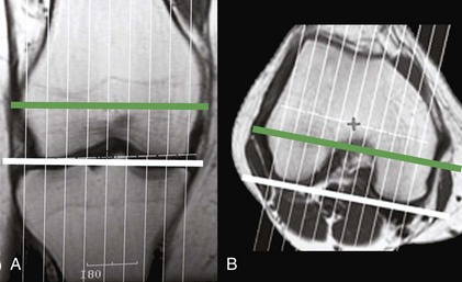
The locator image in the coronal plane that shows the largest projection of the distal femoral condyles is used to adjust the varus-valgus orientation of the plane of the nonorthogonal, oblique, sagittal scan. The nonorthogonal, oblique, sagittal scan plane is aligned perpendicular to a line connecting the cortical-cancellous bone interface of the distal femoral condyles on the locator image in the coronal plane. The locator image in the axial plane that shows the largest projection of the posterior femoral condyles is used to adjust the axial rotation of the plane of the nonorthogonal, oblique, sagittal scan. The nonorthogonal, oblique, sagittal scan plane is aligned perpendicular to a line connecting the cortical-cancellous bone interface of the posterior femoral condyles in the locator image in the axial plane. Because the contour of the posterior femoral condyles from 10 to 160 degrees forms a single radius of curvature, and because the primary transverse axis in the femur about which the tibia flexes and extends is equidistant from the distal and posterior articular surfaces of the femoral condyles, the femoral condyles are projected as circular in the nonorthogonal, oblique, sagittal imaging plane and perpendicular to the primary transverse axis in the femur about which the tibia flexes and extends.10,11,14
A nonorthogonal, oblique, sagittal scan is then acquired of the knee, which is subsequently processed with software to generate a three-dimensional model of the knee. The scanning parameters are selected to provide contrast among fat, joint fluid, cartilage, degenerative and normal menisci, and subchondral, cancellous, and cortical bone. For a 1.5-T scanner and a dedicated knee coil (General Electric Medical Systems, Milwaukee, Wisc), we use these parameters: FRFSE PD, 30 to 35 TE, 2800 to 3400 TR, 31.25-Hz bandwidth, and minimum of two excitations using a 16-cm field of view centered at the joint line of the knee, 512 × 512 matrix, 2-mm slice thickness, with no spacing or gap. The length of each side of a pixel in the oblique sagittal image is 0.31 mm.14
Generation of Three-Dimensional Arthritic and Normal Knee Models
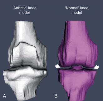
Kinematic alignment of the femoral and tibial components begins with a three-dimensional arthritic knee model generated from the MRI scans, from 44 to 60 slices, depending on the width of the knee (Fig. 121-6). Proprietary software segments the femur, tibia, articular cartilage, and osteophytes from each image and meshes the images together to form a three-dimensional model of the arthritic knee (OtisMed). A series of steps is applied to the arthritic knee model to create a normal knee model. The articular surface of the arthritic knee model is transformed into a knee with a normal articular surface by filling articular defects. Osteophytes are removed to restore ligament length and restore a normal shape to the knee. The normal knee model is then aligned in the coronal plane by adjusting the varus-valgus rotation and proximal-distal position of the tibia until the distance between the femoral and tibial articular surfaces is equal medially and laterally.13,16 This process of creating a normal knee from an arthritic knee by filling defects, removing osteophytes to restore ligament length, and reestablishing a symmetrical medial-lateral joint space borrows from the well-established principles used to align the mobile-bearing unicompartmental knee replacement (i.e., Oxford Knee).
Shape-Matching Femoral and Tibial Components
The three-dimensional model of the femoral and tibial component that best fits the normal knee model is selected by proprietary software (see Fig. 121-2). Algorithms shape-match the femoral component to the restored articular surface of the femur in the normal knee model from 10 to 160 degrees, which kinematically aligns the femoral component by coaligning the transverse axis of the femoral component with the primary transverse axis in the femur about which the tibia flexes and extends. The internal-external rotation of the anterior-posterior axis of the tibial component is set perpendicular to the transverse axis of the femur and femoral component, which kinematically aligns the tibial component to the femoral component. The tibia is centered under the tibial component, which kinematically aligns the tibia to the tibial component.1,7,10,12 In theory, kinematic alignment restores the normal parallel and perpendicular interrelationship among the three kinematic axes of the prearthritic knee.14
Related posts:
 Management of Extra-articular Deformity in Total Knee Arthroplasty With Navigation
 Patellar Instability
 Posterior Cruciate Ligament Reconstruction: Posterior Inlay Technique
 Perioperative Management of the Patient With Coronary Stents
 Venous Thromboembolism Prophylaxis After Knee Surgery: The European Approach
 The Infected Total Knee Replacement
Stay updated, free articles. Join our Telegram channel

Full access? Get Clinical Tree


