INBONE Implant: Features, Technique, and Results
John G. Anderson
Donald R. Bohay
C. Luke Rust
Nicholas A. Cheney
FEATURES
The INBONE (Wright Medical, Arlington, TN) Total Ankle system, released for implantation by the Food and Drug Administration (FDA) in 2005, is the only commercially available total ankle replacement method in widespread use that utilizes an intramedullary guided system for component position, followed by placement of a multipiece stemmed tibial component (Video 5.1). Unlike other systems in which an extramedullary guide uses anatomical landmarks to determine implant placement, the INBONE system uses an external frame in order to direct an intramedullary alignment rod through the bottom of the foot and into the medullary canal of the tibia with fluoroscopic guidance. Tibial and talar bone cuts are then accomplished using a monoblock slotted cutting guide, and a modular tibial stem is then inserted through a standard anterior approach.
TIBIAL STEM
The rationale behind the INBONE Total Ankle system was derived through the examination of total hip and knee arthroplasty techniques. To achieve implant stability and position, these procedures utilize an intramedullary system. Unlike the hip, in which dislocation enables an intramedullary stem to be placed, or the knee, in which joint range of motion allows intramedullary access, the anatomy of the ankle joint does not easily permit the implantation of long-stemmed components. The INBONE tibial component is a modular system in which stacked pieces coated with titanium plasma spray are introduced into the tibial canal and threaded together. The final tibial base plate is then attached by a Morse taper (Fig. 5.1). This system therefore relies more on a vertical bony interface for stability than do other total joint replacement systems, allowing a greater degree of malleolar preservation.
INTRAMEDULLARY GUIDANCE
The INBONE Total Ankle system utilizes an intramedullary guidance system. The guide’s position is determined fluoroscopically and is set through the use of a large leg holder apparatus. Radiopaque alignment rods are manipulated into position until there is colinearity with the tibial shaft in orthogonal views. A 6-mm guide drill is then inserted through the calcaneal fat pad region. It passes anteriorly and medially to the posterior facet of the talocalcaneal joint to enter the tibiotalar articulation, and eventually the tibial canal.
TALAR COMPONENT
To achieve talar component stability, the INBONE Total Ankle system relies on broad coverage of the resected talus in tandem with a titanium plasma spray-coated stem or stems. Depending on the version used, there may be one or more stems. (INBONE I uses a single talar stem, while INBONE II adds two additional anterior talar pegs.) The design of the talar component focuses
on medial-lateral coverage, and is one of the broadest on the market. Similar to its tibial counterpart, it is also a modular system in which the large posterior stem (10 or 14 mm in length) is affixed to the talar dome component by means of a Morse taper. These stems are not intended for subtalar arthrodesis; originally longer, custom stems were available for revision situations. The FDA, however, is currently not allowing their use, even in custom situations. In addition, the INBONE II system uses a sulcus articulation in which the central portion of the talar component is recessed for additional medial-lateral stability. This is matched to a polyethylene component, which is fixed to the tibial component.
on medial-lateral coverage, and is one of the broadest on the market. Similar to its tibial counterpart, it is also a modular system in which the large posterior stem (10 or 14 mm in length) is affixed to the talar dome component by means of a Morse taper. These stems are not intended for subtalar arthrodesis; originally longer, custom stems were available for revision situations. The FDA, however, is currently not allowing their use, even in custom situations. In addition, the INBONE II system uses a sulcus articulation in which the central portion of the talar component is recessed for additional medial-lateral stability. This is matched to a polyethylene component, which is fixed to the tibial component.
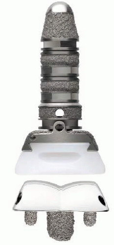 Figure 5.1. INBONE II Total Ankle system. |
PATIENT-SPECIFIC ALIGNMENT
Recently, custom instrumentation has been added—the PROPHECY INBONE. In this technique, a preoperative computed tomography (CT) scan is used to fashion patient-specific alignment cutting guides that determine the tibial and talar cuts. Intramedullary guidance is maintained with the use of a smaller external frame.
TECHNIQUE
APPROACH
The patient is positioned supine with the foot at the end of the bed and the tibial tubercle and foot facing upward, usually requiring a bump to be placed under the ipsilateral hip. Also, a thigh tourniquet is used. A standard anterior approach is made between the extensor hallucis longus and tibialis anterior tendons. Osteophytes are removed from the anterior tibia and talus. (Note: If the Prophecy custom cutting blocks are being utilized, only soft tissue is debrided as the alignment guides are fashioned based on CT scan information and rely on bony anatomy for placement.) At this point, deformity may be addressed. In varus deformities, one should be prepared to release the deep deltoid and superficial deltoid ligaments. In valgus deformities, overdistraction with a larger poly may compensate for lax lateral ligaments. Once the ankle joint is exposed, the assembled leg holder is introduced to the operative field (Fig. 5.2).
INTRAMEDULLARY ALIGNMENT
The leg holder frame is assembled on the back table. The foot is placed into the holder, flush against the foot plate. The heel is then secured with medial and lateral Steinmann pins. It is imperative that the heel rest flat on the foot plate to avoid a posteriorly sloping talar cut. In order to achieve this, gastrocnemius recession or Achilles tendon lengthening may be necessary. The leg is secured to the remainder of the frame with stretch gauze. Prior to inserting the extramedullary guide rods, a perfect mortise view of the ankle is typically obtained. Placing a straight ¼-in osteotome in the medial gutter and making the osteotome lie parallel to the side of the cutting guide before inserting the calcaneal pins and then making the foot holder perfectly parallel to the beam of the fluoroscope is another way of getting a perfect mortise view to start. Medial-lateral and anterior-posterior guide rods are then aligned with the tibial shaft using fluoroscopic guidance (Fig. 5.3). The fins of the guide rods must be centered on orthogonal fluoroscopic views. Small adjustments to table or C-arm position are instrumental in achieving centered guide rods. Once the guide rods are appropriately aligned, a 6-mm transverse incision is made in line with the plantar drill guide. By placing some ink on the trocar and inserting it into the cannula, great precision can be made in placing the small incision for the 6-mm drill. Blunt dissection may then be employed until the plantar surface of the calcaneus is reached to avoid damage to the lateral plantar nerve. Otherwise, the blunt trocar may be used to puncture the plantar fascia and insert the drill. A 6-mm drill is then slowly advanced using a “peck drill” technique so as not to skive on the hard plantar-medial border of the calcaneus (Fig. 5.4). The authors suggest intermittently cleaning the flutes of the drill bit and following the bit fluoroscopically to ensure that it is not deviating from the alignment rods. Once the bit has passed through the tibia, it is usually advanced about 8 cm, based on the tibial stem construct planned. Typically, a four-piece construct is used.
Related posts:

Stay updated, free articles. Join our Telegram channel

Full access? Get Clinical Tree


