Chapter 10 Imaging of Total Knee Arthroplasty
Total knee arthroplasty results in improvement in overall quality of life in more than 90% of patients.79 This remarkable success and factors such as an aging population have led to a dramatic increase in the number of procedures performed and to corresponding increases in the number of imaging studies obtained for assessment (http://www.cdc.gov/nchs/data/nhsr/nhsr005.pdf). In addition to radiography, computed tomography (CT), magnetic resonance imaging (MRI), ultrasonography (US), arthrography, and a number of nuclear medicine studies are now available for evaluation of knee arthroplasty. It is the responsibility of both imagers and clinicians to provide the most efficacious and cost-effective examinations in a particular clinical situation. This chapter reviews some available imaging techniques, expected findings in uncomplicated and complicated cases, and the efficacy of various techniques in assessing complications.
Imaging
Radiographs
Preoperative Radiographs
Preoperative radiographs often include supine anteroposterior (AP) and lateral and tangential patellar views of the affected knee, as well as standing AP and flexed PA views of both knees and an AP standing radiograph of both legs.68 At the Brigham and Women’s Hospital, lateral radiographs are usually obtained cross-table lateral with the knee in maximal extension. When digital radiographs are used, a standard-sized reference object is placed alongside the knee to allow assessment of magnification.
The standing view of both legs allows the mechanical axis (a line drawn from the center of the femoral head to the center of the tibial plafond) and the femoral (along the femoral shaft) and tibial anatomic axes to be defined. Normally, the mechanical axis passes through the center of the knee, and the angle between the anatomic and mechanical axes measures 5 to 8 degrees.73 Standing radiographs of the legs are used to plan the femoral resection, so as to re-create normal mechanical alignment. McGrory and associates, however, found that this examination did not significantly aid in obtaining a neutral mechanical axis as compared with performing a standard femoral cut of 5 degrees.68 Huang and colleagues found measurement of the mechanical axis to have a variability of 1 to 3 degrees.45
Postoperative Radiographs
At the Brigham and Women’s Hospital, in most cases, imaging is not performed immediately after surgery but is done at the first postoperative visit. Usually, both supine radiographs (AP, lateral, and tangential patellar views) and standing radiographic100 views are obtained.
Normal Postoperative Radiographic Appearances
Alignment
Because coronal malalignment can lead to decreased implant survival22 and accelerated wear, careful analysis of component position and leg alignment is warranted. Radiographs are an effective means of evaluating component position in sagittal and coronal planes.
AP and Lateral Knee Radiographs
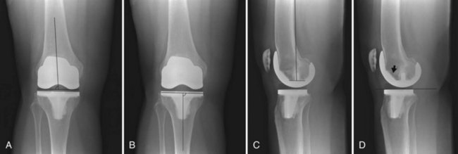
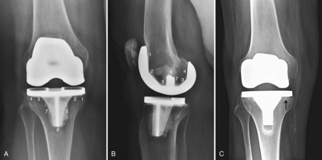
Component position on AP and lateral knee radiographs can be assessed as in Figure 10-1. Tibial resection is generally perpendicular to the anatomic axis of the tibia.9 Femoral resection is more complex owing to the desire to resect the femur perpendicular to its mechanical axis. Approximately 5 to 8 degrees of valgus is present between the femoral condyles and the anatomic axis of the femur.73 The posterior/inferior tilt of the tibial component can be assessed on the lateral radiograph. Increased downsloping of the tibial component (with posterior cruciate ligament [PCL] retaining components) can increase maximum flexion, but excessive tibial downslope can lead to anterior tibial subluxation, posterior polyethylene wear, and lack of extension.12
Standing Radiographs
Axial Alignment
Angulation of the knee in the coronal plane can be measured on standing radiographs of the legs. The angle between the mechanical axis of the femur (drawn from the center of the femoral head to the center of the intercondylar notch) and a line from the middle of the intercondylar eminence to the center of the talus demonstrates the angulation of the knee. Conventional radiographs or digital radiographs can be utilized for this assessment.102
The Mechanical Axis
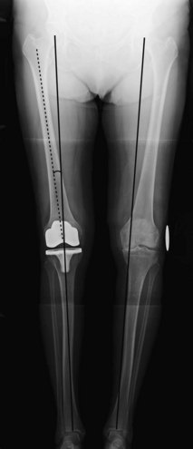
The mechanical axis (a line drawn from the center of the femoral head to the center of the tibial plateau) should intersect the center of the knee73 (Fig. 10-2). The femoral and tibial components should be perpendicular to this line,73 and the joint space should be parallel to the ground.115 Deviations from this alignment should be minimal (within 3 degrees of the normal mechanical axis).121 Some authors consider axial malalignment as mechanical alignment outside the range of 1 degree varus to 2 degrees valgus.14
The Joint Line
In 1986, Figgie and associates noted that restoration of the tibial patellofemoral relationships had an impact on function in patients receiving posterior stabilized condylar knee prostheses.32 Change of 8 mm or less in the height of the joint line (measured as the perpendicular distance from the weight-bearing surface of the tibial plateau to the tibial tubercle) resulted in better functional knee scores, improved range of motion, and absence of patellofemoral pain or mechanical symptoms (Fig. 10-3).
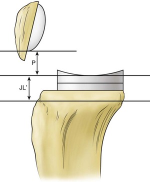
Hofmann and colleagues used measurements from the adductor tubercle to the joint line of the distal femur (in comparison with the normal side or the preoperative radiograph) to assess “proximalization” or “distalization” of the joint line42 (Fig. 10-4). Restoration of the joint line (to within 4 mm of the preoperative or contralateral side) is said to avoid problems such as patella baja, patella alta, extensor mechanism maltracking, lack of motion, and midflexion instability.42
Radiolucent Lines
Development of thin radiolucent lines at the bone/cement or bone/prosthesis interface of less than 2 mm within the first 6 months in a cemented implant or during the first 1 to 2 years in noncemented implants without evidence of progression is considered normal (Fig. 10-5). Evaluation of low contact stress total knee arthroscopy (TKA) with meniscal bearings showed that 99% of radiolucent lines were nonprogressive, but even progressive radiolucent lines did not appear to affect fixation.2 A scoring system for monitoring loosening developed by The Knee Society delineates specific areas to be assessed27 (see Fig. 10-5). This method is complex, and a simplified system has been proposed.7
Patellofemoral Joint
The patellofemoral articulation can be an important cause of postoperative knee pain and prosthetic failure.120 However, the relationship between patellar abnormalities on radiographs and knee symptoms is imperfect.8
Imaging Techniques
Both lateral and tangential patellar views are important for assessing the patellar component and alignment. Numerous methods can be used for obtaining tangential patellar views in preoperative or postoperative individuals. Radiographic positioning alterations such as degree of flexion and weight bearing may significantly alter imaging findings.120 Baldini and associates evaluated weight-bearing tangential patellar radiographs obtained with patients standing and semisquatting with the knees in 45 degrees of flexion.8 Correlation was made between anterior knee symptoms and signs and imaging findings.8 Persistence of patellar tilt of >5 degrees on the patellar dome on the weight-bearing study correlated positively with anterior knee pain.8 None of the measurements made on non–weight-bearing radiographs correlated with pain and clinical scores.8
Radiographic evaluation of the patellofemoral joint includes assessment of patellar tilt, patellar dislocation or subluxation, asymmetry in patellar component positioning,8 “overstuffing,” patellar height, and patellar fracture.32,35 Often postoperative measurements are compared with preoperative ones.
Patellar Height
Figgie and colleagues proposed measuring patellar height as the perpendicular distance from the inferior pole of the patellar implant to the joint line of the prosthesis (see Fig. 10-3). Measurements of between 10 and 30 mm were associated with the best clinical results.32
Patellar Tilt
Patellar tilt is measured as the angle formed between a line drawn along the anterior femoral condyles and a line along the prosthesis/bone interface.53
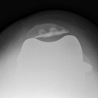
Patellar tilt is not uncommon (Fig. 10-6). For example, Bindelglass and associates found patellar tilt in 31.2% of 234 primary total knee prostheses.17 Patellar tilting in relation to the femoral component changes the contact area and permits the thinner peripheral portion of the patellar component to be subjected to maximum forces.53 Polyethylene deformation, particle shedding, and early failure may occur. Laughlin and coworkers found that patellar tilt may change during the course of postoperative follow-up examinations.53
Articulation (impingement) between the patellar bone and the femoral component may occur. When this is extensive and is associated with sclerosis of the patella on a weight-bearing tangential patellar view, a positive correlation with pain has been found.8
Asymmetry of Patellar Component Placement
Asymmetrical resection greater than 4 mm in the mediolateral dimension or asymmetry of component position in the superior/inferior position as demonstrated on lateral views has been shown to correlate with anterior knee pain.8 Lateral placement may cause retinacular tightness that may be avoided by medial positioning of the patellar component.73
Computed Tomography
Scout View
A relatively low-dose scout view obtained supine has been shown to allow accurate determination of the mechanical and anatomic axes of the femur for surgical planning.115
Improvement in CT techniques has made this modality considerably useful in evaluating complications of TKA. Multidetector helical CT with a higher applied kilovolt peak (140 kVp) improves x-ray penetration and produces superior image quality (although it also increases effective dose).61,92,97 Use of soft tissue reconstruction filters in the setting of metallic prostheses and of wide window settings (width, 3000 to 4000 Hounsfield units [HU]; level, 800 HU) allows evaluation of bone near a prosthesis and is useful in the detection of focal areas of osteolysis.19,108,122 Reformatted images may be helpful in minimizing artifact and demonstrating granuloma extent. Three-dimensional volume-rendered images minimize artifacts usually seen on conventional multiplanar reformatted images.28
Chauhan and associates described CT assessment of component position with relation to the mechanical axis as determined by CT scanning from the acetabular roof to the talar dome.20,56 One potential limitation of this technique is the absence of weight bearing during the examination.
Rotational Alignment of Components
Several methods have been utilized surgically to align the femoral component, such as the Whiteside line (the AP axis of the distal femur),123 the posterior femoral condylar axis, and the transepicondylar axis. The surgical transepicondylar axis connects the point of the lateral epicondyle to the medial sulcus of the medial epicondyle.16 The femoral component should be parallel to this line or slightly externally rotated. Errors in femoral component rotation are common and may lead to patellofemoral complications and anterior knee pain.109 Berger and colleagues found that patellofemoral complications were associated with combined (tibial and femoral) internal rotation, and the greater the rotational abnormality, the worse were the symptoms.14
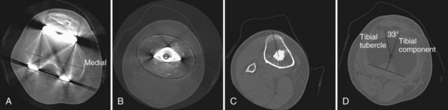
CT scanning can be used to measure the rotation of tibial and femoral components. Berger and coworkers used the transepicondylar axis as a reference to evaluate femoral component rotation and the tibial tubercle as the reference to assess tibial component rotation on CT scans14 (Fig. 10-7). They noted that normal rotation of the femoral condyles is 0.3 ± 1.2 degrees of internal rotation for females and 3.5 ± 1.2 degrees of internal rotation for males in comparison with the surgical epicondylar axis. On the tibial side, the native tibial articular surface (and the correctly positioned tibial component) is in 18 degrees ± 2.6 degrees of internal rotation relative to the tibial tubercle.14 The AP tibial component axis is drawn perpendicular to the posterior edge of the tibial component.16 When the femoral component is parallel to the transepicondylar axis and the tibial component is aligned in 18 degrees of internal rotation in relation to the tibial tubercle, normal patellar tracking results.16 The degree of excessive combined internal rotation of the components was shown to be directly proportional to the severity of patellofemoral complications.16
This method has been difficult to use because the sulcus in the medial epicondyle is frequently difficult to identify. When the prominences of both epicondyles (instead of the medial sulcus) are used, the clinical transepicondylar axis produces a baseline that is more anteriorly and externally rotated (by about 6 degrees).73 The angle between the epicondylar prominences and the posterior condyles is termed the twist angle.3,114
Mismatch between femoral and tibial component rotation may also be problematic.114
MRI
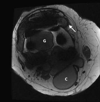
Despite the presence of metal components, MRI has become a viable (and valuable) technique for investigating complications of knee arthroplasty, particularly wear (Fig. 10-8). As summarized by Malchau and Potter and the Implant Wear Group, modifications in pulse sequence parameters and optimized protocols allow soft tissues and areas of osteolysis around the knee and hip prostheses to be evaluated.61 MRI metal suppression techniques include increasing the bandwidth, which diminishes the frequency shift caused by metallic components, and increasing the signal-to-noise ratio by increasing the number of acquisitions and by using fast spin-echo techniques with longer echo-train lengths.61,118 The interested reader is referred to the reference by Malchau and Potter for specific protocol information.61
Complications
The most commonly cited reasons for failed total knee replacement include aseptic loosening, instability, infection, hardware failure, and malalignment, with more than 50% of revisions occurring within the first 2 years following primary surgery.105 The most common causes of early failure (within 2 years) were infection and instability; long-term complications included polyethylene wear and aseptic loosening.31,105
Disorders of the Patella and Extensor Mechanism
A retrospective review of 1272 consecutive total or partial knee arthroplasties by Melloni and associates disclosed patellar complications in 3.6%.70 Complications included instability/dislocation, fracture, osteonecrosis, infection, erosion, impingement, patellar or quadriceps tear, and loosening of the patellar component (Fig. 10-9). The most common complication is patellar instability related to maltracking, often due to internal rotation of the tibial or femoral component.70 Many patellar complications can be detected on radiography, but any underlying rotatory malalignment of components is best assessed on CT.
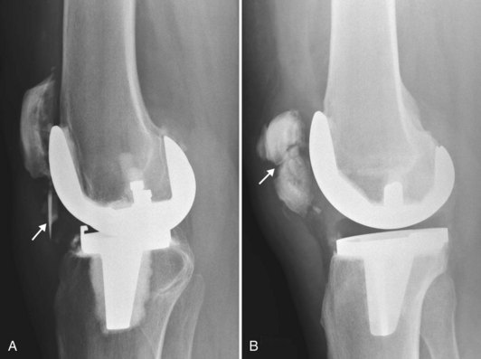
Patellar fragmentation and sclerosis have been attributed by Melloni and colleagues to osteonecrosis (see Fig. 10-9). Patellar fractures may be difficult to identify on radiography and may be asymptomatic.70 Over-resection of the patella may predispose to fracture.73 Evaluation of any accompanying patellar component loosening and of remaining bone stock of the patella helps classify fractures for treatment planning.73 Quadriceps or patellar tendon disruption may be confirmed on ultrasound examination.70
Polyethylene Liner Wear
Multiple factors influence tibial component polyethylene liner wear, including weight and activity level of the patient, polyethylene thickness, alignment, relationship between the polyethylene component and the metal surface of the femoral and tibial components, and physical properties of the polyethylene.34,37,40,73 The thickness of the polyethylene liner depends on the tensile forces needed to balance the knee ligaments, but it should measure at least 8 mm initially.37,40
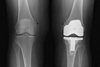
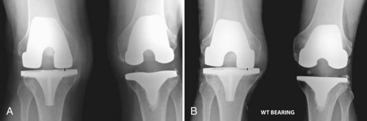
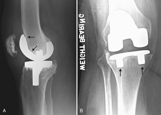
In TKA, polyethylene wear may be evaluated on standing AP and lateral views with the x-ray beam parallel to the tibial baseplate (Fig. 10-10). The distance from the femoral condyles to the tibial baseplate can then be measured. Large amounts of polyethylene wear will be detected as moderate to severe narrowing of the distance between the femoral component and the metal backing (baseplate); early or mild joint space narrowing may be more subtle and may be appreciated only if comparison is made between serial examinations.73 Eventually, wear may progress to allow metal-to-metal contact, erosion of the tibial metal backing, and metal synovitis (Fig. 10-11). Development of a popliteal cyst in patients with a TKA may be an indirect sign of prosthetic wear or loosening.77,83 Ultrasonography has been shown to accurately evaluate polyethylene thickness.107,126
Loosening, Particle Disease, and Osteolysis
Particle shedding, especially that caused by polyethylene wear, is the primary reason for long-term failure of TKA.13,30,80,81,105 The natural response to particulate debris begins with the release of inflammatory cytokines, which stimulate osteoclasts and inhibit osteoblasts. The biologic cascade of polyethylene wear–related osteolysis is dependent on several factors, including the number of wear particles, the size and surface morphology of the wear particles, and the rate at which particles accumulate in periprosthetic tissues.43 Particles migrate along the “effective joint space”103 and produce changes in the joint, along the bone cement or prosthesis bone interfaces, and sometimes in adjacent soft tissues and lymph nodes.
Loosening
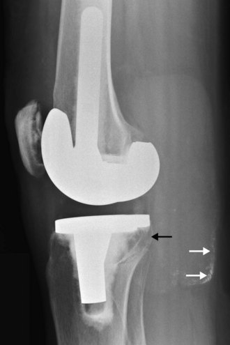
The tibial component loosens more frequently than the femoral component. Radiographic indicators that are suggestive of loosening include the development of focal radiolucencies greater than 2 mm, interval increases in the width of an existing radiolucency, cement fracture, and changes in component position.73 Radiolucent zones in both noncemented and cemented implants are often bordered by a thin layer of lamellar bone, which is produced by remodeling (Fig. 10-12). Wide lucent lines around the stem are more likely to be indicators of loosening than are peripheral lucent zones. Detection of radiolucent lines requires that they be seen in tangent, and this is facilitated by fluoroscopy or by special views (such as an oblique posterior condylar view).29,66,74,75,81 The tibial component tends to shift into a varus position with subsidence into the medial plateau and collapse of the cancellous bone,62,66 while a loose femoral component tends to shift into flexion (see Fig. 10-12).
Related posts:
 Articular Cartilage: Biology, Biomechanics, and Healing Response
Advanced Technologies in Performing Total Knee Arthroplasty: Roundtable Discussion
In Vivo Mechanics and Vibration of the Knee Joint
Secondary, Spontaneous, and Postarthroscopy Osteonecrosis of the Knee: Diagnosis and Management
Advances in Mechanical Compression Devices
Articular Cartilage Injury and Adult OCD: Treatment Options and Decision Making
Articular Cartilage: Biology, Biomechanics, and Healing Response
Advanced Technologies in Performing Total Knee Arthroplasty: Roundtable Discussion
In Vivo Mechanics and Vibration of the Knee Joint
Secondary, Spontaneous, and Postarthroscopy Osteonecrosis of the Knee: Diagnosis and Management
Advances in Mechanical Compression Devices
Articular Cartilage Injury and Adult OCD: Treatment Options and Decision Making
Stay updated, free articles. Join our Telegram channel

Full access? Get Clinical Tree


