A 5 kg head travelling at 9.9 m/s has a kinetic energy of 245 J. Dropping the 5 kg head 5 m will result in the head having 245 J on impact. On impact, work is performed on the head to stop it. If we consider conservation of energy and just potential energy (PE), kinetic energy and work (W), we arrive at the following relationship:
If the helmet brought the 245 J impacting head to a full stop in 30 mm, the average force during the impact would be approximately 8200 N. However, typically, the peak force is significantly greater than the average. A liner would need to be considerably thicker than 30 mm to deform during the impact by 30 mm. This simple and hypothetical example presents the challenge in developing a helmet. An impact force of at least 8200 N will result in considerable head injury. If the helmet liner was 45 mm with a 5 mm shell, then the minimum thickness of the helmet will be 50 mm. If a more effective helmet is desired, greater liner deformation is required, which means a larger and thicker helmet.
One topic not considered above is the stiffness and viscoelasticity of the liner. The material needs to be able to deform 30 mm in this impact. A very rigid material will not deform and a very soft material will fully deform, both doing very little to attenuate the impact. In both of these extreme cases, the head will be brought to a sudden stop in much less than 30 mm.
As foreshadowed in the introduction, the test conditions need to reflect relevant injury risk management objectives, so that the test method will be suitable and the materials and design of the helmet appropriate [3]. Test methods will be considered later in the chapter.
32.3.2 Load Distribution
Helmets can provide a load distributing function so that the pressure placed on the head is reduced. For example, if the head collides with a rock, a small area of the head is initially loaded. That area progressively gets larger and engages more of the surface area of the head. If there is sufficient force in this situation, local brain contusion will occur and the skull will deform and fracture. The impact will also cause a laceration of the scalp. A shell can reduce the local pressure and deformation. A shell can distribute the impact force over a larger surface area of the head and reduce the risk of head injury.
Some helmets are also assessed for their ability to resist a penetrating load and their integrity under such a load.
Great success has been achieved by helmets to reduce severe head injury through impact acceleration management and load distribution. Attention has turned to other mechanisms of brain injury, such as angular acceleration, and how helmets might be improved to reduce angular acceleration further [3, 6].
32.3.3 Restraint Systems
The restraint system is also critical as it retains the helmet on the head and in a position and orientation that provides protection. Ideally, a helmet should stay in place under all circumstances; however, in extreme sports there may be situations in which helmets could give rise to tensile forces that could injure the cervical spine. Aerodynamic and hydrodynamic forces, e.g. ‘bucketing’, might lead to a situation in which the forces are pulling the helmet away from the head and through the restraint system causing tensile forces on the cervical spine. This could lead to asphyxia or cervical spine injury. For the typical helmet, e.g. bicycle or motorcycle, we consider the minimum strength requirement not the maximum. Research on bicycle and motorcycle helmets gives us confidence that this is an appropriate approach [1, 2]. Research does not show, for example, that bicycle helmets increase neck injury risks or strangulation risks. This does not mean that there are no cases in which this has occurred; however, it means that on a population level, this does not emerge as a risk. It might be necessary to consider restraint system strength requirement limits for some helmets used in extreme sports. Again, this is highly dependent on the risks in the sport and the risk management objectives. These are very challenging ethical issues. If helmet performance moved in this direction, then a test would require a helmet restraint system to be able to sustain a specific test load, e.g. 1000 N, without exceeding a specified elongation, e.g. 20 mm, but then fail at a specified higher test load, e.g. 1500 N. This could be engineered through selection of materials. For example, the selection of webbing will minimise elongation, and the plastic buckle could be designed to fail at a specific force.
32.4 Standards and Test Methods
32.4.1 Scope and Objectives
Certain aspects of helmet design and function are codified into a written document called a Standard or Technical Specification [3]. These documents contain normative (mandatory) and informative (guidance) requirements. The documents typically indentify the scope and objectives of the standard, e.g. a helmet for skydiving that is intended to prevent concussion and superficial head injuries arising from impacts inside the plane, with other skydivers and in an uncontrolled low speed landing. This describes what injuries the helmet is intended to prevent and the circumstances in which the helmet is intended to function. This statement needs to be consistent with the test specifications. An alternative might be for a helmet for competitive alpine skiing and snowboarding, e.g. a helmet for competitive alpine skiing and snowboarding that is intended to prevent serious head injuries arising from high speed impacts. The test specifications for the two hypothetical helmets will be quite different. The most obvious difference is that the test impacts for the alpine helmet will be more severe, i.e. at a higher velocity, than the skydiving helmets. In addition, in the impact tests the expected performance will be different. It might be reasonable to establish these standards along the lines described above, from a practical perspective. Helmets can perform within the specifications described above for alpine sports and skydiving. However, it would not be possible within our current technology to have a skydiving helmet that protects the head from an impact at terminal velocity, e.g. 54 m/s.
A helmet standard or technical specification may include tests of: impact energy attenuation, load distribution, strength of retention system (dynamic or static), stability (dynamic or static), buoyancy and resistance to penetration. The standard can include an inspection protocol regarding internal and external projection dimensions, in addition to marking and labelling. Tests can be specified to be undertaken on helmets conditioned to hot, cold or wet. Additional tests can be specified for visors and other accessories. Three of these test methods will be described: impact energy attenuation, helmet stability and restraint system strength.
32.4.2 Impact Energy Attenuation
Impact energy attenuation tests involve dropping a headform upon which a helmet is placed onto an anvil from a height (Fig. 32.1 ). The height, or velocity, the headform and the anvil are defined. In some tests a projectile is fired at the helmet headform or an impact is applied using a special device [7]. A projectile impact is probably more relevant in a projectile sport than dropping the helmet onto an anvil. More recently, methods have been developed with which to subject helmets to oblique impacts, where there are two impact velocity components [8, 9].
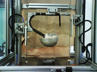
Fig. 32.1
Drop assembly for guided two wire drop test. The headform is shaped like a human cranium and can be rotated to orient the impact to selected sites on the helmet. The helmet is placed over the headform. In this specific test configuration, a single accelerometer is mounted inside the head, and it is always oriented along a vertical axis, regardless of the orientation of the headform
Table 32.1 presents the differences between three standards and the 2013 International Ski Federation (FIS) rule for helmets in downhill (DH), super G (SG) and giant slalom (GS) competitions.
Table 32.1
Comparison of impact energy requirements in standards for snow sports helmets
Standard | Drop height (m) | Peak headform accel. (g) | Anvil | Drop height (m) | Peak headform accel. (g) | Anvil | Drop height (m) | Peak headform accel. (g) | Anvil |
|---|---|---|---|---|---|---|---|---|---|
Snell RS-98a | 2.0 | <300 | Flat | 1.6 | <300 | Hemi | 1.6 | <300 | Edge |
EN 1077: 2007 | 1.5 | <250 | Flat | – | – | – | – | – | – |
ASTM F2040 – 06
Related posts:Stay updated, free articles. Join our Telegram channel
Full access? Get Clinical Tree
 Get Clinical Tree app for offline access

|


