Extensively Coated Stems
C. Anderson Engh Jr
In 1983, the Food and Drug Administration approved the first porous-coated femoral implant for use without cement. This implant, the Anatomic Medullary Locking stem (AML, DePuy, Warsaw, IN), was characterized by a circumferentially porous-coated, straight, nontapered distal cylindrical rod coupled with a circumferentially porous-coated proximal metaphyseal triangular shape. Current studies of the AML have documented 98% femoral component survivorship at 20 years (1). Excellent results with this stem have also been reported in scenarios historically not deemed appropriate for porous-coated fixation, such as in patients with avascular necrosis, those with rheumatoid arthritis, and the elderly with osteoporosis (2,3,4). Today, extensively porous-coated femoral implants are available from many manufacturers.
INDICATIONS
The nonselective use of porous-coated femoral stems at our institution for all total hip replacements for 20 consecutive years has demonstrated no short-term difference in clinical outcome based on age, sex, diagnosis, or bone quality (5,6,7). Patients over 65 years of age or those with osteoporosis do not have poorer clinical results or less reliable osseointegration than do younger patients (8). The single most important factor predicting the clinical result of extensively porouscoated stems is the quality of the initial prosthetic fit within the femur, particularly within the diaphysis (9). This finding is more a characteristic of the surgical technique than of any patient parameter.
The requirement for using an extensively coated stem, therefore, is simple: the presence of bone capable of providing initial mechanical support for the implant and of mounting an osteogenic (i.e., typical fracture healing) response sufficient for ingrowth. Exceptionally few patients do not meet this criterion.
CONTRAINDICATIONS
The contraindications relate to the diameter or the femoral canal. Since stems are not available below 10.5 mm, patients with very small-diameter canals are not a candidate. The same is true for very large-diameter stems. The largest size is 22.5 mm. Patients with canals this large are perhaps treated best with a cemented stem or a revision-type stem that is available in the larger diameters.
PREOPERATIVE PREPARATION AND TEMPLATING
Surgical planning of a total hip replacement with an extensively porous-coated femoral component is similar to planning for other implants. Every patient who is scheduled for a total hip replacement must have an examination that allows the surgeon to plan if the hip needs to be kept the same length or lengthened. Not uncommonly, the standing leg length and the radiographic hip length are not
the same, and the difference must be resolved so that a target surgical correction can be templated. The most common cause of a discrepancy is the presence of a contracture. Both a flexion contracture and an adduction contracture of the surgical hip will cause the hip to have false shortening. In contrast, an abduction contracture of the operative hip will cause false lengthening. Other causes for a discrepancy between the radiographic hip length and the standing leg length include fixed pelvic obliquity and a difference in the leg length originating below the hip, such as arthritic knee deformities, leg fractures, or ankle and foot deformities.
the same, and the difference must be resolved so that a target surgical correction can be templated. The most common cause of a discrepancy is the presence of a contracture. Both a flexion contracture and an adduction contracture of the surgical hip will cause the hip to have false shortening. In contrast, an abduction contracture of the operative hip will cause false lengthening. Other causes for a discrepancy between the radiographic hip length and the standing leg length include fixed pelvic obliquity and a difference in the leg length originating below the hip, such as arthritic knee deformities, leg fractures, or ankle and foot deformities.
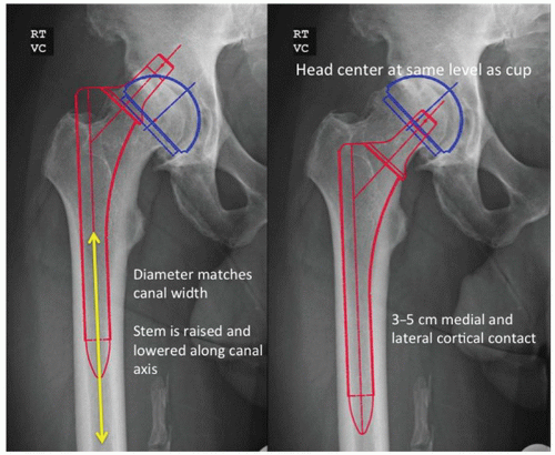
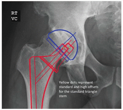
There are six steps in the templating process for an extensively porous-coated femoral component. First, the leg length correction is determined as previously described. Second, the size and position of the acetabular component are determined. Third, the diameter of the distal, cylindrical portion of the stem is determined by placing the template in line with the center of the femur in the femoral diaphysis. The correct size is that which fills or is slightly larger than the isthmus so that porous coating will contact a distance of at least 3 to 5 cm of the medial and lateral endosteal cortices (Fig. 15-1). The fourth step involves determining the level of the femoral neck resection and the prosthetic neck length. With the center of the acetabulum previously marked and the femoral template aligned to the diaphysis, the template is raised or lowered until the head directly overlays the acetabular center or lies directly above the acetabular cup center a distance equal to the desired amount of increased limb length. The level of the neck cut is then marked and the neck length chosen. The fifth step involves selecting the appropriate proximal implant geometry and offset that adequately fills the proximal femur and recreates femoral offset based on the level of the neck resection. Extensively porous-coated systems usually contain two proximal geometries (Fig. 15-2). Femoral neck offset options vary by manufacturer. The final step involves templating with the lateral radiograph. With the lateral template at the desired level, the stem should not risk perforation of the anterior cortex in a femur with an exaggerated anterior bow.
SURGICAL TECHNIQUE
All surgical approaches to the hip have been used to place extensively porous-coated stems. However, the 6-inch straight stem design requires moderate retraction of the hip abductors, making these stems more difficult to insert with anterior abductor-sparing approaches. We will describe the posterior approach, which remains the most common surgical approach for total hip arthroplasty (9,10).
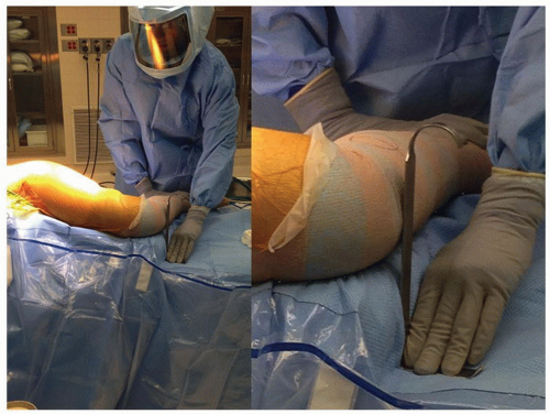
The patient is placed in the lateral decubitus position. We tape the lower (nonoperated) leg to the table, with the hip flexed 30 degrees and the knee at a 90-degree flexed position. If the upper leg is placed directly on top of the lower leg and both knees are flexed at 90 degrees, it is possible to compare leg lengths. The surgeon can use a right angle and a ruler to measure (at the knees) the apparent difference in femoral lengths (Fig. 15-3).
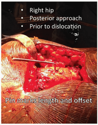
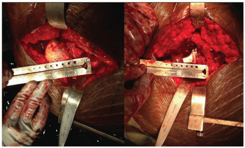
After the superficial dissection and the arthrotomy, but prior to dislocation of the hip, a 5/32-inch threaded Steinmann pin is placed through the gluteus medius muscle into the ileum. The pin is then bent twice at 90-degree angles so that the exposed tip touches the greater trochanter. This point is marked with a stay stitch to monitor offset and length after placement of the trial implants (Fig. 15-4).
After hip dislocation, the distance from the lesser trochanter to the center of the femoral head is measured and recorded (Fig. 15-5). One goal of femoral preparation will be to approximate this distance by repeating the measurement using the position of the femoral trial ball. The femoral head is resected with the provisional cut. Surgeons can elect femoral or acetabular first preparation. A femoral first technique has the surgeon place the trial at the templated level before acetabular exposure, thus avoiding a high initial neck resection, which can make acetabular exposure difficult. Additionally, the femoral anteversion that is difficult to change is accessed, and the acetabular position that can easily be adjusted can be matched to the femur.
The first step in femoral preparation is to create a cylindrical tube with straight rigid reamers. Correct pilot hole positioning is critical for proper femoral component placement. The pilot hole should be at least 2 mm larger than the size planned for the intramedullary canal. Making the pilot hole larger than the anticipated distal implant size reduces the possibility of eccentric reaming of the intramedullary canal. As progressively larger reamers are inserted into the medullary canal, these reamers must not contact the pilot hole. If this contact does occur, the hole must be enlarged to prevent the proximally located pilot hole from influencing the direction of the reamers distally (Fig. 15-6).
The distance reamed can be determined from marks on the reamer that reference either the greater trochanter or the medial neck cut depending on the system used. As the canal is reamed, the surgeon can feel and hear the reamer bite femoral cortex. The proper diameter reamer will bite cortical bone for 3 to 5 cm—that size should be within one size of the templated stem diameter. The absence of such correspondence should serve as a warning that the reaming is not being performed correctly. In this case, an intraoperative x-ray should be considered to check the reamer orientation.
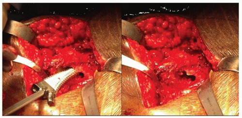
Once the femoral diaphysis has been prepared, rasps are used to prepare the metaphyseal bone (Fig. 15-7). Care is taken not to remove excessive metaphyseal bone. Although the stem is distally
fixed, proximal bone contact and ingrowth is important for long-term fixation and to prevent migration of wear debris distally. Most systems have two metaphyseal broach sizes. The smaller is used first and seated to the templated level based on the two intraoperative measurements. The more reproducible is the templated distance from the proximal tip of the greater trochanter to the lateral aspect of the femoral broach (Fig. 15-8). The second measurement is the distance from the lesser trochanter to the center of a femoral trial ball on the broach neck segment. If the broach is at the proper level and there is remaining metaphyseal cancellous bone, then the large triangular broach is used. At this point, the goal of recreating femoral anatomy is addressed. When the surgeon is happy with the femoral length, the acetabulum is prepared with a femoral first technique or a trial reduction is performed if the acetabulum has already been prepared.
fixed, proximal bone contact and ingrowth is important for long-term fixation and to prevent migration of wear debris distally. Most systems have two metaphyseal broach sizes. The smaller is used first and seated to the templated level based on the two intraoperative measurements. The more reproducible is the templated distance from the proximal tip of the greater trochanter to the lateral aspect of the femoral broach (Fig. 15-8). The second measurement is the distance from the lesser trochanter to the center of a femoral trial ball on the broach neck segment. If the broach is at the proper level and there is remaining metaphyseal cancellous bone, then the large triangular broach is used. At this point, the goal of recreating femoral anatomy is addressed. When the surgeon is happy with the femoral length, the acetabulum is prepared with a femoral first technique or a trial reduction is performed if the acetabulum has already been prepared.
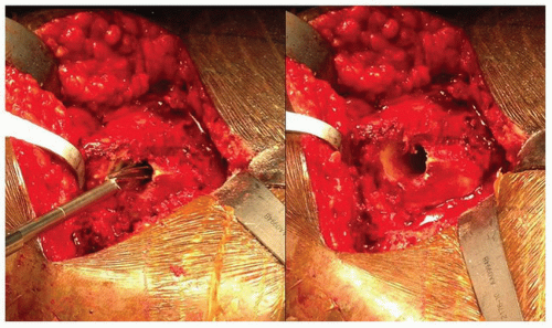 FIGURE 15-6 The drill is being directed in part by the overhanging greater trochanter; therefore, the pilot hole needs to be enlarged to prevent varus positioning of the femoral component. |
Stay updated, free articles. Join our Telegram channel

Full access? Get Clinical Tree


