Chapter 123 Computer-Assisted Navigation
Minimally Invasive Surgery for Total Knee Replacement
Much of the hesitation in using minimally invasive surgery (MIS) in total knee replacement (TKR) evolves from coping with the complexities of a smaller incision without visual cues. When using a constrained exposure, reliance on instruments rather than direct visual reference is paramount. Second, sequencing to augment exposure becomes important to afford better access. If one adds deformity or increased body mass to the equation the traditional visual references, angular and translational position is compromised. Such dependence on traditional instruments, which rely on some degree of visually estimating cuts, may result in less dependable accuracy.3–5,10,12,16
Computer-assisted surgery (CAS), also known as surgical navigation, becomes necessary to reclaim lost visual reference and confirm accuracy lost in MIS exposure.17 If the surgeon avoids the use of small incisions because of lost accuracy, the addition of CAS can allay concerns about this deficiency. Although doubt still exists in regard to the efficacy of CAS to improve performances, this accuracy ensures the surgeon that the extra step of precision has been taken.* The confidence gained in achieving accuracy with documentation easily overcomes any reticence of a short learning curve in adoption of this technology.
However, there are other factors in addition to the time required to learn the systems. Lack of confidence in believing what the instruments are reading can hinder surgical progress.15 Although some readings are often not realistic or believable, the computer is usually smarter than the surgeon. Once reliance and confidence in CAS have been achieved, less time is spent using traditional instruments to confirm readings and more rapid surgery can be performed.
Choices in Systems
Infrared Computer-Assisted Surgery
 -inch self-drilling or self-tapping threaded pins in varied lengths.
Lateral Monitor and Medial Pin Insertion Option
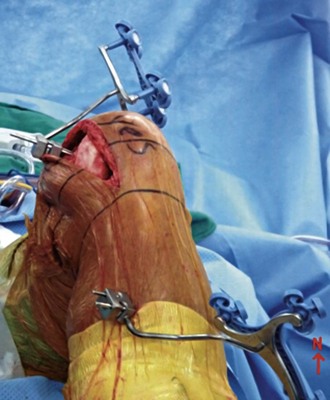
The tibia insertion point is best started at or approximately 4 cm below the tibial tubercle to avoid cutting jig interference and remain free of the incision access. The pins are inserted with the first pin bicortically applied at a 45- to 60-degree angle off the anterior crest of the anteroposterior (AP) plane of the tibia and the second pin rotated sufficiently to allow just enough room for the tracker array to clear the drapes and the crest of the tibia (Fig. 123-1). Some tracker pin blocks allow multiaxial rotation, so the exact rotation may not be necessary. However, fixed tracker blocks require some attention to rotation and elevation.
Intraincisional Considerations
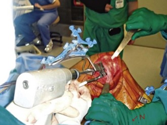
The greatest obstacle comes with the reduced room for accessing cutting jigs. This commits one to a freehand cut on the femur and tibia or modifying current cutting jigs to lie over and behind the view of the trackers to make the cuts. My preference is to use a freehand cut with a small two-pin block on the femur (Fig. 123-2). This is done by holding the cutting block in one hand, with a paddle array in the cutting slot. The other hand holds a pin or screw on a drill, which provides a means of fine correction of varus-valgus once resection depth is established.
Surgical Technique
This is undoubtedly the most difficult part of the procedure, but all the following steps hinge on access gained from the proximal tibial approach. When performing this, the knee is flexed to 90 degrees and tactile sensation provides the primary end point of saw blade excursion. A wide patellar retractor (fat fork) is placed laterally, a forked retractor posteriorly, and a cruciate or Hohmann retractor on the medial side to protect the medial collateral ligaments. In large patients, 80 mm is the furthest excursion of the saw blade to the poster lateral corner, although 60 mm is adequate for women. The posterior retractor protects the popliteal structures. Use caution not to abrade the patellar tendon anteriorly with the blade oscillations because it can cut as easily by the edge as it does on the cutting end. When sawing is complete, a twist of the saw is usually enough to pop the remaining capsule free of any bound bony tissue. For large patients with marginal osteophytes or for osteoporotic individuals, blade twisting to elevate the respected bone may not be sufficient, or worse yet can mash the tibial metaphases. I use a 1.5-inch osteotome gently inserted across the osteotomy and then a second  -inch inserted on top. This provides protection to the tibia to prevent penetration into the soft cancelous bed from the distraction maneuver. The
  -inch osteotome is twisted with a pliers or the back of a locked Cocker, to dislodge the bone enough which aids in the initially freeing of the fragment (Fig. 123-3).
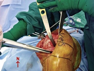
This now makes the femoral waypoint acquisition ready by viewing the posterior condyles or using the posterior referencing rotation jigs. Note first any abrasive wear or skid marks in relation to Whiteside’s line. This can be an important clue to an aberrant trajectory of true knee flexion rather than anatomic points. Once the computer has inputted waypoints on the femoral rotation, anterior cortex, and distal condylar surface, the distal femur can be resected. A freehand jig is my preference, but it takes some practice to keep the three axes in perspective on CAS monitors (see Fig. 123-3). As noted, be sure that your jig tracker is in the dorsal or saggital plane and not oblique to prevent composite angle changes. I start with the on-screen crosshairs to get varus-valgus roughed in. Then, while holding the cutting guide on the medial side of the femur in one hand, move it to the approximate calculated femoral resection (10 mm in most systems). I use the formula of 10 mm + = 1 mm resection for every 4-degree lag of extension noted preoperatively to achieve adequate flexion contracture correction. I have found this to be an accurate guide for providing adequate extension in patients with flexion contractures not corrected by osteophyte removal, similar to other authors.2
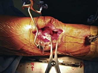
The knee is now ready for final clean-up in extension (Fig. 123-4). I prefer a large laminar spreader to separate the bone ends if a more elaborate foot holder is not available. I pay particular attention to three problem bleed areas. The first is the inferior genicular vessel to the lateral meniscus, just adjacent to the popliteus tendon. Second is the posterior cruciate found in the top of the box cut or in the notch. The final active vessel is the medial inferior genicular vessel to the medial meniscus and capsule. Even if I see no active bleeding, I generally use a Bovie or Bipolar (high-frequency bipolar unit) in these regions while the tourniquet is down. Then the capsule is injected. Avoid the popliteal corner because of the proximity of the peroneal nerve. I use an injection cocktail of 15 mL of 0.5% ropivacaine (Naropin), 100 mL of 0.2% ropivicaine, 0.5 mL of epinephrine 1/1000, a 30-mg solution of ketorolac (Toradol), and 10 mg of morphine sulfate. As a natural depot, the pes anserinus is injected with 10 to 15 mL while the remaining 25-mL allotment is placed in the muscle tissue and medial capsule, near the pes anserinus insertion.
Related posts:
 Articular Cartilage: Biology, Biomechanics, and Healing Response
Advanced Technologies in Performing Total Knee Arthroplasty: Roundtable Discussion
In Vivo Mechanics and Vibration of the Knee Joint
Secondary, Spontaneous, and Postarthroscopy Osteonecrosis of the Knee: Diagnosis and Management
Advances in Mechanical Compression Devices
Articular Cartilage Injury and Adult OCD: Treatment Options and Decision Making
Articular Cartilage: Biology, Biomechanics, and Healing Response
Advanced Technologies in Performing Total Knee Arthroplasty: Roundtable Discussion
In Vivo Mechanics and Vibration of the Knee Joint
Secondary, Spontaneous, and Postarthroscopy Osteonecrosis of the Knee: Diagnosis and Management
Advances in Mechanical Compression Devices
Articular Cartilage Injury and Adult OCD: Treatment Options and Decision Making
Stay updated, free articles. Join our Telegram channel

Full access? Get Clinical Tree


