Chapter 108 Cementless Total Knee Designs
History
Cement use in arthroplasty remains a controversial issue and has decreased sharply in total hip, total shoulder, and total ankle arthroplasty. Although cement fixation still is widely used in the knee, new studies report remarkable success with the osteointegration technique, and some new porous metal materials appear promising.7,17,68 Many cemented total knee replacement designs introduced through the years have failed and have been removed from the market. Those that remain are the few select designs that have performed reasonably well because of specific design characteristics, including a well-fixed tibial component with an effective stem, multiple sizes of femoral components, a generous curvature on each femoral condyle, and a conforming polyethylene surface with a large articular contact surface area.22 With the advent of new instruments, these cemented implants, even when placed by inexperienced arthroplasty surgeons, have had a high rate of success. Cement fixation, however, remains a source of consternation for implant designers. Attempts to produce a cemented all-polyethylene tibial component resulted in a loosening rate in excess of 20% at 5 years,14 and the use of cemented total knee replacement in younger, active patients resulted in high failure because of loosening.29,42 One of the engineering considerations that has not been addressed satisfactorily is fixation of the cement mantle to the metal substrate; this is especially important for the metal-backed tibial component.
The primary goal of noncemented fixation of total joint arthroplasty is to improve the longevity of the implant. Many cementless designs were unsuccessful even at early follow-up periods, but others have been highly successful. In fact, the femoral component in almost all cementless designs reliably achieves fixation to bone and commonly is used in hybrid total knee arthroplasty.25 The tibial component in cementless total knee arthroplasty, as in cemented arthroplasty, has been the greatest source of problems related to fixation because most designs have begun with inadequate fixation.
Fixation of the femoral component generally has not been as difficult as that of the tibial component, but femoral component design is far from simple. Weight bearing with the knee in extension can generate high shear stress at the anterior and posterior flange surfaces if the surfaces are adherent to bone.53 Weight bearing in flexion can generate high shear stress at the distal surfaces if the bone is not seated posteriorly and the component is not fixed rigidly against shear loading.53
Load transfer characteristics of the femoral component observed in a clinical radiographic study66 are predictable from the study of Walker and associates53 on fixation of the femoral component. If the anterior and posterior flange surfaces of the femoral component are bonded to bone, the femoral shaft transfers weight-bearing load in the form of shear stress through the flange surfaces during weight bearing in extension, but the load can be transferred to the distal surfaces in the form of compressive stress if the anterior and posterior flange surfaces are not bonded to bone. Compressive loading is desirable because it encourages ossification at the porous metal-bone interface and promotes hypertrophy of adjacent cancellous bone. Whiteside and Pafford found that gaps at the distal surface failed to close and developed a surrounding halo of cancellous bone atrophy, but this is not surprising because the hypertrophy produced by compressive loading on either side of the gap leads to stiffening of the bone and thus increases its ability to transfer load.66 As the load is transferred in increasing proportion through hypertrophic bone, atrophic bone overlying the gap becomes less capable of bearing load, thus transferring more load to areas that contact the metal surface. It is difficult to see how load sharing and equalization of stress could be expected to occur, and it is not surprising that gaps, when carefully scrutinized, were seldom seen to close. Current designs incorporate anterior porous coating to ensure early complete bonding of bone to metal and accept higher shear stress on the anterior flange surfaces. This is acceptable because of improvement in the bonding strength of the porous metal surface to the bare metal. The distal stress relief that occurs because of this design feature is deemed preferable to the anterior femoral osteolysis that can occur if this surface is left unbonded to bone.68
Walker and colleagues53 further predicted that unbonding of the posterior flange surfaces would cause stress relief of these surfaces during weight bearing in flexion. In the study by Whiteside and Pafford,66 all specimens showed evidence of greater hypertrophy at the posterior bevel and posterior flange surfaces than at any other surface. The observed pattern of cancellous hypertrophy suggested that weight-bearing loads were transmitted primarily in compression through the cancellous bone and through the interfaces of both components. The smooth posterior femoral flange surface did not appear to affect posterior femoral condylar hypertrophy. Smooth flange surfaces and smooth stem and pegs on the femoral component did not appear to bear significant axial load.
The tibial component traditionally has been considered to present the major load transfer and fixation problems. Adherence of the stem and pegs to supporting cancellous bone may cause proximal stress shielding, as well as high shear stress at the bone-prosthesis interface and high bending stress in the stem.36 According to Murase and coworkers36 in a study of cemented designs, the best configuration to achieve stability and yet avoid proximal stress shielding included a short central stem for toggle control. Tibial component fixation systems without a central stem do not achieve adequate toggle control to prevent lift-off and sinking of the tibial component in response to an eccentrically applied load.1,27,28,44,54 Although some current designs do not incorporate stems or peripheral stems, these principles have not changed, and they must be considered in modern implant design. Eccentric and tangential loading also causes shear stress at the interface between bone and the undersurface of the tray, and these stresses must be considered in implant design.*
Load transfer in the tibia is important when bone quality and stress relief osteopenia are considered. Low-strain readings around the peripheral rim correspond to peripheral atrophy seen in a radiographic study, and the area of high-strain readings on the metaphyseal flare corresponds to the area where the hypertrophic cancellous bone joined the metaphyseal cortex.66 These findings suggest that tibial load bearing causes primarily compressive stress, and that the load is transferred through the cancellous bone to the cortical bone of the tibial metaphysis, to a certain extent bypassing the proximal peripheral rim of the tibia. High strain in the anterolateral area of the tibia suggests that the bone surface in this area deforms to a greater extent than do other areas after total knee arthroplasty.
In the medial condylar area, the bone is denser than in the central condylar area and therefore is more capable of transferring axial load.66 The relatively soft cancellous bone in the upper surface of the tibia23 makes this area especially vulnerable to compressive failure, and the need for a stem on the tibial tray to protect this area is abundantly documented in the biomechanical literature. Bartel and coworkers1 demonstrated in a finite element analysis that prostheses without a stem are likely to sink into soft areas of the tibial surface when the component is loaded eccentrically. Walker and associates53 and Lewis and colleagues28 found in separate studies that fixation of the tibial component was best achieved by a rigid tray and a central metal stem. Results of the study by Bartel and coworkers1 also suggest that peripheral contact between the tray and the cortex of the upper part of the tibia would alleviate this problem of sinking. However, the peripheral rim of the proximal end of the tibia does not have a true cortex,56 and the hardest bone is not arranged around the periphery but instead is usually found on the medial and lateral posterior surfaces and medially just beneath the articular cartilage. Therefore, a finite element model that includes a substantial cortex probably would predict inappropriate benefits from rim contact with the upper tibial surface. All tibiae in the study in which sinking of the tibial component occurred had good rim contact.
The loading pattern of the tibia during normal gait is complex. Although eccentric anterior and posterior loading occurred during weight bearing in flexion and extension in Whiteside and Pafford’s study,66 no attempt was made to quantify this effect. In general, it appeared possible to achieve reliable fixation of the femoral and tibial components without clinically significant stress shielding in the distal femur or the proximal tibia.
Applying a rigid metal tray to a flat surface of cancellous bone does not provide adequate resistance to compressive failure of cancellous bone, lift-off of the opposite side, or toggling micromotion of the component. When early results showed problems with fixation, stems and peripheral screws began to appear on these implant designs. Biomechanical studies clearly indicated that peripheral screws and stems on the tibial component were highly effective, and that micromotion of the tray was unacceptably large without these fixation-enhancing features.34,51 An aspect of tibial component fixation that is commonly overlooked but is probably the most important is preparation of the upper tibial surface. Small surface irregularities and incongruities can have a devastating effect on fixation, but this aspect of fixation has received little attention in most cementless tibial component designs.
Biomechanical studies have shown that when tibial components are fixed to the bone surface with only short pegs, they sink on the loaded side and lift off on the opposite side.51 Both stems and screws were effective in controlling sinking and lift-off in the study by Volz and associates.51 Radiographic and histologic studies have shown that bone ingrowth into a tibial tray is infrequent,9 which suggests that micromotion may be unacceptably large. Achieving rigid initial fixation is the most important factor in promoting bone ingrowth. Miura and colleagues34 evaluated the effects of screws through the tibial tray and a sleeve on the stem to improve fixation of the tibial component. Bone strength was a major factor in preventing subsidence and micromotion. Without mechanical fixation, poor bone quality was associated with unacceptably large micromovement. The anterolateral portion showed the least bone strength in the proximal tibial surface. Hvid and Hansen reported that bone strength at the anterolateral and intercondylar regions was very low.21
In a study by Miura and coworkers,34 screws were effective in controlling micromovement under axial and shear loading. When components with screws were compared with those without screws, lift-off was found to be reduced by more than 90%. Screws shifted the tilting center lines posteriorly. This finding suggested that the main effect of the screws was to prevent lift-off. Screws also ensured initial bone-implant contact. Miura and associates reported that they frequently observed the component to settle on the tibial surface when the screws were tightened. Screws did not eliminate micromotion under axial loads, but they did change the pattern of micromotion. Without screws, micromotion was associated with lift-off and sinking, whereas with screws, sinking and lift-off were minimized, but downward bending of the tray was significantly greater. Although it is uncertain how much micromotion is acceptable while bone ingrowth occurs, it should be minimized as much as possible. A material with an elastic modulus similar to that of cancellous bone may be optimal for stress distribution beneath the tibial tray, but it may also increase the micromotion caused by bending. Results of the study by Miura and colleagues34 suggest that techniques to lessen bending of the tibial tray minimize micromotion. Mechanisms to prevent bending of the tibial tray might include a material with a higher elastic modulus and the addition of an arch to support the tibial tray.
The mechanical effect of a tight stem appeared in the study of Miura and coworkers34 to improve the keel effect by packing surrounding soft cancellous bone and thus improving the press-fit effect, increasing the surface area, and placing the stem closer to the inner surface of the posterior cortex. Use of a tight stem alone was effective in preventing lift-off and sinking under axial loads, but the use of screws had overriding effects on sinking and subsidence. Addition of the stem to a screwed-down tibial component had a small (but statistically significant) effect in controlling lift-off. The location of the tilting axis varied with each specimen and with each group. The effect of screws was to shift the tilting axis posteriorly in comparison with groups without screws. This is an important mechanical effect and is probably a result of the resistance to lift-off afforded by the screws. If lift-off was unchecked, the tilting axis shifted toward the point of load application, thus decreasing the area through which the load was transferred. This increased pressure and aggravated sinking.
Design-Related Failure
Implant materials and design features that have occurred coincidentally with cementless total knee replacement designs and are responsible for implant failure are flat polyethylene,5 heat-pressed polyethylene,4 and patch porous-coated surfaces.62 The combination of these features, along with poor quality assurance of polyethylene and gamma irradiation of this material, has caused remarkable wear problems that have led to clinically significant osteolysis.12,49,58,62 This type of wear and osteolysis is not a function of the fixation method; instead, it is caused by design features that have incidentally been associated with cementless fixation.
Femoral Component Design
Fracture of the metal femoral component has rarely been a problem in the development of total knee designs, but those that fractured were usually cementless designs that generated excessive stress through an attempt to conserve bone. Stress in noncemented knees is different from that generated in knees fixed with cement,53,66 and these differences in point and direction of load application may focus high stress on critical cross-sectional dimensions. Porous coating decreases the strength of metal implants because it thins the cross-sectional dimension, especially at corners and junction areas, where the metal may already be at critical dimensions.
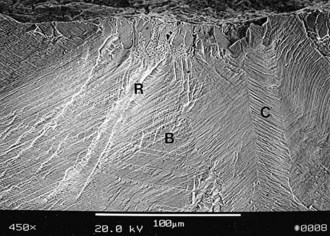
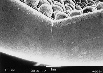
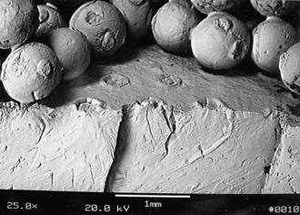
When the Ortholoc II knee femoral component was designed in the mid-1980s, a double porous bead layer was applied to the inner surface for cementless fixation.65 This design was changed soon thereafter to a single layer of beads to improve strength characteristics because within a year of implantation, the manufacturer received reports that fracture of the femoral component had occurred in the design with a double layer of beads, especially those of smaller size (Figs. 108-1 to 108-3). In the author’s series of 613 Ortholoc II prostheses with a double bead layer on the femoral component, four fractures occurred. All four implants fractured at the junction between the posterior bevel and the distal surface of the medial femoral condyle.65
Loads applied to the outer surface of the implant by body weight and muscle force cause bending moments that tend to close the implant and apply tensile stress to the outer surface. However, loads applied to the inner surface are likely to have the opposite effect. If the anterior and posterior surfaces are not allowed to adhere to bone, load is borne on the distal surfaces preferentially.53,66 Because the Ortholoc II femoral component was designed to avoid axial load bearing by its anterior and posterior flange surfaces, surgical technique that over-resected the distal surface in relation to the bevel surfaces could have resulted in load bearing exclusively through the inner bevel surfaces. If the implant contacted only the anterior and posterior bevel surfaces and was not also adherent to the surfaces, a wedge would be created, and the femoral component would straighten slightly with weight-bearing loads. Application of these cyclic bending loads on the distal portion of the implant probably produced a bending moment that generated tensile load on the inner surfaces.
Tibial Component Design
An inflammatory response to particulate debris has been identified as the primary cause of osteolysis in total knee arthroplasty.40 Debris contained within the joint minimally affects the surrounding bone, but once it gains access, the osteolytic attack is aggressive. Design features of implants that allow particulate debris access to the bone include the configuration of the porous coating, the stability of the locking mechanism that secures the polyethylene articulating surface to the tibial tray, and the amount of intra-articular pressure within the joint.
Smooth metal surfaces that separate pads of porous coating have been shown in experimental and clinical studies to produce metaphyseal and diaphyseal osteolytic lesions by conducting debris into areas of bone that are not protected by the synovial membrane particle transfer system that captures wear debris and transfers it to the local lymphatic system.6,12,30,57,69 Although these osteolytic lesions have been ascribed to cementless fixation and to the use of screws,12 they are rare unless the tibial component design includes patch porous coating on the undersurface of the tray, inadequate fixation of the tibial component, and mechanisms that produce large amounts of particulate debris in the knee. As has been seen in cementless total hip arthroplasty, osteolysis occurs when patches of porous coating on the implant are separated by smooth metal surfaces. These smooth metal surfaces form fibrous tissue bridges that conduct polyethylene debris and joint fluid to the diaphyseal endosteal area, where no mechanism exists to diminish the inflammatory response. Porous coated patches on the Harris-Galante cementless total hip femoral prosthesis appeared to be the cause of a high rate of femoral diaphyseal osteolysis, regardless of the method of fixation to bone.30,69
This phenomenon can be explained by a study conducted by Ward and associates,57 in which the porous coating around the extraosseous portion of proximal tibial prostheses was observed to seal the bone-cement interface from invasion by polyethylene debris, whereas prostheses with smooth surfaces connecting the joint to the bone-cement interface had high rates of osteolysis and loosening.
This observation also was supported in a laboratory study by Bobyn and colleagues,6 who reported the effects of porous coating and smooth metal surfaces on migration of particulate debris from the joint cavity in rabbits. Partially porous coated rods readily conducted polyethylene debris from the knee joint into the medullary canal of the femur, but circumferentially porous coated rods had bone and tissue penetration into the porous coating that acted as a barrier to migration of the polyethylene debris.
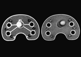
The Ortholoc Modular tibial component (Wright Medical Technology, Arlington, Tenn), which has patches of porous coating separated by smooth metal bridges on its undersurface, was clinically compared with the Ortholoc II tibial component (Wright Medical Technology), which has continuous porous coating on the undersurface. The rate of osteolysis was found to be statistically significantly greater in knees with the patch porous coating design (Fig. 108-4).62 Osteolysis did not occur around the tibial stem or pegs in 675 patients whose knees were replaced with the Ortholoc II design, but three nonprogressive osteolytic lesions were found around screws on postoperative radiographs. Partial radiolucency was seen beneath the tibial surface in 27 knees. None have been revised for osteolysis. In contrast, radiographically detectable osteolysis was seen around the tibial stem in 28 (23%) of 124 Ortholoc Modular total knee prostheses with long (150 mm) stems (Figs. 108-5 and 108-6). Of those 28, none had radiographically identifiable osteolysis around the screws or pegs, but 15 (54%) had partial radiolucent lines that extended beneath at least half the tray on the anteroposterior or lateral view, and 4 (14%) had radiolucency beneath the entire tibial surface on either radiographic view. An additional 15 (12%) of 124 knees had radiographically identifiable radiolucency around the stem. Radiographically detectable osteolysis was seen around the tibial stem in 19 (17%) of 112 Ortholoc Modular total knee prostheses with short (75 mm) stems. Thirty (27%) knees had radiolucent lines that extended halfway across the undersurface of the tray, and 9 (8%) knees had complete radiolucent lines under the tray on the anteroposterior or lateral radiographic view.
Stay updated, free articles. Join our Telegram channel

Full access? Get Clinical Tree


